Table of Contents
Advertisement
Advertisement
Table of Contents

Subscribe to Our Youtube Channel
Related Manuals for ClearView ip-73


Summary of Contents for ClearView ip-73
- Page 1 Clearview HD IR Waterproof Network Dome Camera Quick Start Guide Version 1.2.0...
- Page 2 Welcome Thank you for purchasing our network camera! This quick start guide is designed to be a reference tool for your system. Please keep this start guide well for future reference. Please open the accessory bag to check the items one by one in accordance with the list below. Contact your local retailer ASAP if something is missing or damaged in the bag.
- Page 3 Thunder-proof device is recommended to be adopted to better prevent thunder. The grounding studs of the product are recommended to be grounded to further enhance the reliability of the camera. 6. Daily Maintenance Please shut down the device and then unplug the power cable before you begin daily maintenance work.
-
Page 4: Table Of Contents
Table of Contents ..........................1 ......................1 ..................1 ......................... 3 ...................... 3 ............5 Quick Configuration Tool ...................... 6 Overview ........................6 Operation ........................6 Web Operation ........................8 Network Connection....................8 Login and Main Interface ..................8 ............. 11... -
Page 5: Figure
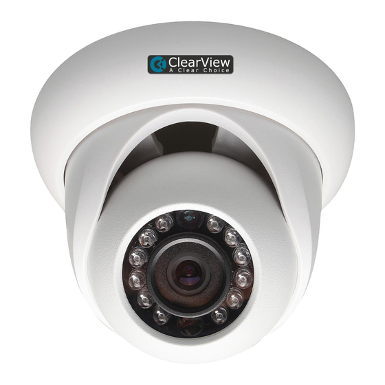
You can refer to the following figure for multiple-function combination cable information. See Figure Figure 1-1 Multiple-function combination cable Please refer to the following sheet for detailed information. Component Component Name Component 1 Device lens Component 2 Dome body Component 3 Dome enclosure Port Name... -
Page 6: Figure 1-3 Dimension Illustration
Please refer to the following two figures for dimension information. The unit is mm. See Figure 1-2 and Figure 1-3. Figure 1-2 Dimension illustration 1 Figure 1-3 Dimension illustration 2... - Page 7 Important Before the installation, please make sure the installation environments can at least support 3x weight of the camera. Please follow the steps listed below to install the device. Please refer to Figure 2-1 for reference. Step 1 Turn clockwise to remove the decoration ring from the snap joints. Step 2 Please take the installation position map in the accessories bag, and then paste it on the ceiling or the wall according to your monitor area requirements.
- Page 8 Figure 2-2 Device installation illustration 2 Note This series product supports two cable exits. One is from the bottom and the other is from the side. Please refer to the following figure for cable exit from the side information. Figure 2-3 Device installation illustration 3 Please earth the GND port of the device to enhance the device reliability.
- Page 9 Figure 2-4 Device installation illustration 4 Important Please use RESET button when device is running. Step1 Please refer to step1 and step2 in chapter 2.1to loose the dome body. Push a little bit; you can take the dome body from the gland cover. Step2 Take the dome body out and then turn the top cover hard to remove.
-
Page 10: Quick Configuration Tool
3 Quick Configuration Tool 3.1 Overview Quick configuration tool can search current IP address, modify IP address. At the same time, you can use it to upgrade the device. Please note the tool only applies to the IP addresses in the same segment. 3.2 Operation Double click the “ConfigTools.exe”... - Page 11 In the configuration tool search interface (Figure 3-1), please select a device IP address and then double click it to open the login interface. Or you can select an IP address and then click the Login button to go to the login interface. See Figure 3-3. In Figure 3-3, you can view device IP address, user name, password and port.
-
Page 12: Web Operation
4 Web Operation This series network camera products support the Web access and management via PC. Web includes several modules: Monitor channel preview, system configuration, alarm and etc. 4.1 Network Connection Please follow the steps listed below for network connection. Make sure the network camera has connected to the network properly. - Page 13 Figure 4- 2 Web login If it is your first time to log in, system pops up warning information to ask you whether install web plug- in or not after you logged in for one minute. For detailed plug-in installation, please refer to the Web Operation Manual included in the resource CD.
- Page 14 Please refer to the Web Operation Manual included in the resource CD for detailed operation instruction.
- Page 15 Toxic or Hazardous Materials or Elements Component Name Cr VI PBDE Circuit Board ○ ○ ○ ○ ○ ○ Component Device Case ○ ○ ○ ○ ○ ○ Wire and Cable ○ ○ ○ ○ ○ ○ Packing ○ ○ ○...
- Page 16 Clearview HD IR Waterproof Network Dome Camera User s Manual Version 4.0.1...
- Page 17 Welcome Thank you for purchasing our Network camera! This user’s manual is designed to be a reference tool for your system. Please read the following safeguard and warnings carefully before you use this series product! Please keep this user’s manual well for future reference!
-
Page 18: Important Safeguards And Warnings
Important Safeguards and Warnings 1 Electrical safety All installation and operation here should conform to your local electrical safety codes. The power shall conform to the requirement in the SELV (Safety Extra Low Voltage) and the Limited power source is rated 12V or 24V AC DC in the IEC60950-1. (Refer to general introduction) Please note: Do not connect two power supplying sources to the device at the same time;... - Page 19 Do not touch the CCD (CMOS) optic component. You can use the blower to clean the dust on the lens surface. Always use the dry soft cloth to clean the device. If there is too much dust, please use the water to dilute the mild detergent first and then use it to clean the device.
- Page 20 Table of Contents ......................1 ........................1 ........................1 ......................2 ....................3 ..........................9 ......................9 ..................9 ....................... 11 ....................11 ............13 Quick Configuration Tool ....................14 Overview ......................... 14 Operation ........................ 14 Web Operation ........................16 Network Connection....................
- Page 21 This series network camera integrates the traditional camera and network video technology. It adopts video data collection, transmission together. It can connect to the network directly without any auxiliary device. This series network camera uses standard H.264 video compression technology, which maximally guarantees the video quality.
- Page 22 Please refer to the following sheet for network camera performance specification. Model IP-73 Parameter Main Processor TI Davinci high performance DSP Embedded LINUX System Support real-time network, local record, and remote operation at the Resources same time. User Interface Remote operation interface such as WEB, DSS, PSS System Status Bit stream statistics, log, and software version.
- Page 23 Φ 113 86 Weight 280g(Excluding box) Installation Fixed on the wall, ceiling and etc. Please refer to the following sheet for factory default setup information. Default Setup Setup Item IP-73 Config File Normal Brightness Contrast Sharpness Saturation Anti-flicker Outdoor Exposure Mode...
- Page 24 Default Setup Setup Item IP-73 Flip Normal Profile Management Bit stream General type Encode mode H.264 Resolution 720P (1280*720) PAL: 25 Frame Rate(FPS) NTSC:30 Bit Rate Type Main Recommende Stream 1536-6124Kb/S d Bit Bit Rate 4096 I Frame interval Watermark...
- Page 25 Default Setup Setup Item IP-73 Record Path C:\RecordDownload Host Name Ethernet Card Wire Mode Static Device MAC address when it is shipped out of the Mac Address factory IP Version IPV4 IP Address 192.168.1.108 Subnet Mask 255.255.255.0 TCP/IP Default 192.168.1.1...
- Page 26 Default Setup Setup Item IP-73 Port Anonymity Disable User Name anonymity Password **** Sender none Authenticatio n (Encryption mode) Title (Subject) IPC Message Attachment Enable Mail Receiver 0 seconds Email Test Disable interval=60 seconds UPnP Enable UPnP Disable SNMP Port...
- Page 27 Default Setup Setup Item IP-73 Command Enable Disable Anti-dither 5 seconds Record Enable Channel Motion Detect Record Delay 10 seconds Send Email Disable Snapshot Disable Enable Disable Record Enable Channel Video Masking Record Delay 10 seconds Send Email Disable Snapshot...
- Page 28 Default Setup Setup Item IP-73 Time Zone GMT+08:00 System Time Sync Disable DST Type Date Start Time 00:00:00 of Jan.1 End Time 00:00:00 of Jan.2 Disable NTP Server clock.isc.org Port 10 minutes Update Period Anonymous Account Disable Login Auto Reboot...
- Page 29 You can refer to the following figure for multiple-function combination cable information. See Figure Figure 2-1 Multiple-function combination cable Please refer to the following sheet for detailed information. Component Component Name Component 1 Device lens Component 2 Dome body Component 3 Dome enclosure Port Name...
- Page 30 Please refer to the following two figures for dimension information. The unit is mm. See Figure 2-2 and Figure 2-3. Figure 2-2 Dimension illustration 1 Figure 2-3 Dimension illustration 2...
- Page 31 Important Before the installation, please make sure the installation environments can at least support 3x weight of the camera. Please follow the steps listed below to install the device. Please refer to Figure 3-1 for reference. Step 1 Turn clockwise to remove the decoration ring from the snap joints. Step 2 Please take the installation position map in the accessories bag, and then paste it on the ceiling or the wall according to your monitor area requirements.
- Page 32 Figure 3-2 Device installation illustration 2 Note This series product supports two cable exits. One is from the bottom and the other is from the side. Please refer to the following figure for cable exit from the side information. Figure 3-3 Device installation illustration 3 Please earth the GND port of the device to enhance the device reliability.
- Page 33 Figure 3-4 Device installation illustration 4 Important Please use RESET button when device is running. Step1 Please refer to step1 and step2 in chapter 3.1to loose the dome body. Push a little bit; you can take the dome body from the gland cover. Step2 Take the dome body out and then turn the top cover hard to remove.
- Page 34 4 Quick Configuration Tool 4.1 Overview Quick configuration tool can search current IP address, modify IP address. At the same time, you can use it to upgrade the device. Please note the tool only applies to the IP addresses in the same segment. 4.2 Operation Double click the “ConfigTools.exe”...
- Page 35 In the configuration tool search interface (Figure 4-1), please select a device IP address and then double click it to open the login interface. Or you can select an IP address and then click the Login button to go to the login interface. See Figure 4-3. In Figure 4-3, you can view device IP address, user name, password and port.
-
Page 36: Network Connection
5 Web Operation This series network camera products support the Web access and management via PC. Web includes several modules: Monitor channel preview, system configuration, alarm and etc. 5.1 Network Connection Please follow the steps listed below for network connection. Make sure the network camera has connected to the network properly. - Page 37 Figure 5- 2 Web login If it is your first time to log in, system pops up warning information to ask you whether install web plug- in or not after you logged in for one minute. For detailed plug-in installation, please refer to the Web Operation Manual included in the resource CD.
- Page 38 Please refer to the Web Operation Manual included in the resource CD for detailed operation instruction.
- Page 39 I can not boot up Please click RESET button for at least five seconds to restore the device or factory default setup. operate properly. The water leakage The unauthorized front or rear cap remove many result in water occurred. leakage. The glass front cap has sustained heavy push or strike.
- Page 40 Toxic or Hazardous Materials or Elements Component Name Cr VI PBDE Circuit Board ○ ○ ○ ○ ○ ○ Component Device Case ○ ○ ○ ○ ○ ○ Wire and Cable ○ ○ ○ ○ ○ ○ Packing ○ ○ ○...
- Page 42 Pompano Beach, FL 33064 5. ClearView CCTV Inc assumes no risk and shall be subject to no liability for damages or loss resulting from the specific use or application made of the Products. ClearView CCTV’s liability for any claim, whether based on breach of contract, negligence, infringement of any rights of any party or product liability, relating to the Products shall not exceed the price paid to ClearView CCTV Inc for such Products or the published MSRP, whichever is less.
Need help?
Do you have a question about the ip-73 and is the answer not in the manual?
Questions and answers