Cisco Aironet 1570 Series Installation Manual
Outdoor
Hide thumbs
Also See for Aironet 1570 Series:
- Ordering manual (17 pages) ,
- Hardware installation manual (10 pages) ,
- Mounting (52 pages)
Table of Contents
Advertisement
Quick Links
Cisco Aironet 1570 Series Outdoor Access
Point Hardware Installation Guide
Last Updated: January 12, 2016
Cisco Systems, Inc.
www.cisco.com
Cisco has more than 200 offices worldwide.
Addresses, phone numbers, and fax numbers
are listed on the Cisco website at
www.cisco.com/go/offices.
Text Part Number: OL-32138-01
Advertisement
Table of Contents

Related Manuals for Cisco Aironet 1570 Series


Summary of Contents for Cisco Aironet 1570 Series
- Page 1 Cisco Aironet 1570 Series Outdoor Access Point Hardware Installation Guide Last Updated: January 12, 2016 Cisco Systems, Inc. www.cisco.com Cisco has more than 200 offices worldwide. Addresses, phone numbers, and fax numbers are listed on the Cisco website at www.cisco.com/go/offices.
- Page 2 OR ITS SUPPLIERS HAVE BEEN ADVISED OF THE POSSIBILITY OF SUCH DAMAGES. Cisco and the Cisco logo are trademarks or registered trademarks of Cisco and/or its affiliates in the U.S. and other countries. To view a list of Cisco trademarks, go to this URL: www.cisco.com/go/trademarks.
-
Page 3: Table Of Contents
Safety Precautions when Installing Antennas Safety Instructions for Antennas and Radios Avoiding Damage to Radios in a Testing Environment Safety Instructions for Powering the Access Point Translated Safety Warnings Cisco Aironet 1570 Series Outdoor Access Point Hardware Installation Guide OL-32138-01... - Page 4 Supported Antennas AP1572I Internal Antennas AP1572E External Antennas Non-Cisco Antennas Antenna Configurations Installing External Antennas Antenna N-Type Connector Locations External Antenna Mounting Configurations Omni Antennas AIR-ANT2513P4M-N= AIR-ANT2588P3M-N= AIR-ANT2413P2M-N= and AIR-ANT5114P2M-N= Cisco Aironet 1570 Series Outdoor Access Point Hardware Installation Guide OL-32138-01...
- Page 5 4-35 Troubleshooting C H A P T E R Finding the Product Serial Number Guidelines for Using the Access Points Important Notes Convergence Delays Bridge Loop Controller DHCP Server Cisco Aironet 1570 Series Outdoor Access Point Hardware Installation Guide OL-32138-01...
- Page 6 Guidelines for Operating Cisco Aironet Access Points in Japan B-11 Japanese Translation B-11 English Translation B-11 VCCI Statement for Japan B-12 Administrative Rules for Cisco Aironet Access Points in Taiwan B-12 Chinese Translation B-12 English Translation B-13 Cisco Aironet 1570 Series Outdoor Access Point Hardware Installation Guide OL-32138-01...
- Page 7 A P P E N D I X Configuring DHCP Option 43 A P P E N D I X Overview Configuring Option 43 for 1570 Series Access Points Cisco Aironet 1570 Series Outdoor Access Point Hardware Installation Guide OL-32138-01...
- Page 8 Contents Cisco Aironet 1570 Series Outdoor Access Point Hardware Installation Guide viii OL-32138-01...
-
Page 9: Preface
Series Outdoor Access Point Hardware Installation Guide. Objectives This publication explains the steps for installing the Cisco Aironet 1570 Series Outdoor Access Point (called the access point, or abbreviated as AP in this document). The access point is available in an internal antenna model with cable modem (AP1572IC), an external antenna AC model (AP1572EAC) and an external antenna model with cable modem (AP1572EC). -
Page 10: Organization
Cautions use the following conventions: Means reader be careful. In this situation, you might do something that could result in equipment Caution damage or loss of data. Warnings use the following conventions: Cisco Aironet 1570 Series Outdoor Access Point Hardware Installation Guide OL-32138-01... - Page 11 üblichen Verfahren zur Vorbeugung vor Unfällen vertraut. Suchen Sie mit der am Ende jeder Warnung angegebenen Anweisungsnummer nach der jeweiligen Übersetzung in den übersetzten Sicherheitshinweisen, die zusammen mit diesem Gerät ausgeliefert wurden. BEWAHREN SIE DIESE HINWEISE GUT AUF. Cisco Aironet 1570 Series Outdoor Access Point Hardware Installation Guide OL-32138-01...
- Page 12 Använd det nummer som finns i slutet av varje varning för att hitta dess översättning i de översatta säkerhetsvarningar som medföljer denna anordning. SPARA DESSA ANVISNINGAR Cisco Aironet 1570 Series Outdoor Access Point Hardware Installation Guide OL-32138-01...
- Page 13 Figyelem Cisco Aironet 1570 Series Outdoor Access Point Hardware Installation Guide xiii OL-32138-01...
- Page 14 Brug erklæringsnummeret efter hver advarsel for at finde oversættelsen i de oversatte advarsler, der fulgte med denne enhed. GEM DISSE ANVISNINGER Cisco Aironet 1570 Series Outdoor Access Point Hardware Installation Guide OL-32138-01...
- Page 15 Cisco Aironet 1570 Series Outdoor Access Point Hardware Installation Guide OL-32138-01...
-
Page 16: Related Documentation
Click on Cisco Aironet 1570 Series or on the models listed. This opens the corresponding Step 3 product/model support page which has links to all related guides and software downloads. For information on deploying this access point in a network, see the Cisco Aironet 1570 Series Access Point Deployment Guide, at: http://www.cisco.com/c/en/us/td/docs/wireless/technology/apdeploy/8-0/AP_1570_DG/b_Aironet_AP 1570_DG.html... -
Page 17: Obtaining Documentation And Submitting A Service Request
Subscribe to What’s New in Cisco Product Documentation, which lists all new and revised Cisco technical documentation as an RSS feed and delivers content directly to your desktop using a reader application. The RSS feeds are a free service. - Page 18 Obtaining Documentation and Submitting a Service Request Cisco Aironet 1570 Series Outdoor Access Point Hardware Installation Guide xviii OL-32138-01...
-
Page 19: Chapter 1 Product Overview
C H A P T E R Product Overview The Cisco Aironet 1570 Series Outdoor Access Point (hereafter called the access point or AP) is a wireless outdoor access point which is designed for use in a variety of network configurations. The access point can be configured, monitored, and operated through a Cisco wireless LAN controller (hereafter called a controller). -
Page 20: Product Ids And Supported Regulatory Domains
C4—Indicates Power-over-cable with Japanese domain (J8) cable modem supporting – 5-65/108-1002 MHz Diplex Filter, and 8x4 or 16x4 or 24x8 channel bonding options. AC— indicates AC power supply, applicable only to external antenna models. – Cisco Aironet 1570 Series Outdoor Access Point Hardware Installation Guide OL-32138-01... - Page 21 Click this URL to browse to a list of countries and regulatory domains supported by the 1570: www.cisco.com/go/aironet/compliance Product IDs of Access Point Models in the Cisco Aironet 1570 Series The following table shows the nine product IDs based on radios, antenna types and powering options:...
-
Page 22: Parts Of Each Access Point Model
Face of the AP The Face of the access point has the recognizable Cisco logo on it. It is devoid of any ports and connectors. For AP1572EC and AP1572EAC models, the face of the AP has screw holes on it (see... - Page 23 Chapter 1 Product Overview Parts of each Access Point Model Figure 1-3 Face of the AP , on AP1572IC model Cisco logo Cisco Aironet 1570 Series Outdoor Access Point Hardware Installation Guide OL-32138-01...
-
Page 24: Back Of The Ap
AP1570EC models. Not provided in AP1570EAC model. Screw covering Cable RF Attenuator, labeled "7". Cable RF Attenuator provided only in AP1570IC and AP1570EC models. Not provided in AP1570EAC model. Cisco Aironet 1570 Series Outdoor Access Point Hardware Installation Guide OL-32138-01... -
Page 25: Head Of The Ap
The Head of the AP faces upwards when the AP is mounted in a vertical orientation. The head of the AP for the internal antenna model is devoid of any ports and connectors (see Figure 1-6), and is different from that of the external antenna models (see Figure 1-7). Cisco Aironet 1570 Series Outdoor Access Point Hardware Installation Guide OL-32138-01... - Page 26 Chapter 1 Product Overview Parts of each Access Point Model Figure 1-6 Head of the AP , on AP1572IC model Cisco Aironet 1570 Series Outdoor Access Point Hardware Installation Guide OL-32138-01...
- Page 27 Head of the AP , on AP1572EC and AP1572EACmodels Spot for mounting the GPS antenna (here, showing the Antenna port labeled “3” on the AP GP antenna mounted). Antenna ports labeled “4” on the AP Cisco Aironet 1570 Series Outdoor Access Point Hardware Installation Guide OL-32138-01...
-
Page 28: Base Of The Ap
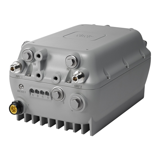
Stinger trim measure for cutting any non-Cisco cable Screw covering Reset Button stinger to size Status LEDs labeled “A” to “D” The LEDs are visible when AP is installed in both horizontal and vertical orientations. Cisco Aironet 1570 Series Outdoor Access Point Hardware Installation Guide 1-10 OL-32138-01... - Page 29 Stinger trim measure for cutting any non-Cisco cable stinger to size Screw covering Reset Button Antenna N-type connector port 1 The LEDs are visible when AP is installed in both horizontal and vertical orientations. Cisco Aironet 1570 Series Outdoor Access Point Hardware Installation Guide 1-11 OL-32138-01...
- Page 30 Antenna N-type connector port 2 Antenna N-type connector port 1 Status LEDs labeled “A” to “D” The LEDs are visible when AP is installed in both horizontal and vertical orientations. Cisco Aironet 1570 Series Outdoor Access Point Hardware Installation Guide 1-12 OL-32138-01...
-
Page 31: Left Side Of The Ap
The Left side of the access point is devoid of any ports and connectors. The left side of the AP is similar across all AP models (see Figure 1-11). Figure 1-11 Left Side of the AP Cisco Aironet 1570 Series Outdoor Access Point Hardware Installation Guide 1-13 OL-32138-01... -
Page 32: Right Side Of The Ap
Console port, labeled “5” on the AP Metal plate for attaching grounding lug Labels showing Product ID and port numbering scheme The console interface is via an RJ-45 port. Cisco Aironet 1570 Series Outdoor Access Point Hardware Installation Guide 1-14 OL-32138-01... - Page 33 Serial port, labeled “12” on the AP Console port, labeled “5” on the AP Metal plate for attaching grounding lug The console interface is via an RJ-45 port. Cisco Aironet 1570 Series Outdoor Access Point Hardware Installation Guide 1-15 OL-32138-01...
- Page 34 Chapter 1 Product Overview Parts of each Access Point Model Cisco Aironet 1570 Series Outdoor Access Point Hardware Installation Guide 1-16 OL-32138-01...
-
Page 35: Preparing For Installation
Safety Instructions for Antennas and Radios, page 2-7 • Avoiding Damage to Radios in a Testing Environment, page 2-7 • Safety Instructions for Powering the Access Point, page 2-8 Translated Safety Warnings, page 2-9 • Cisco Aironet 1570 Series Outdoor Access Point Hardware Installation Guide OL-32138-01... -
Page 36: Safety Warnings
Chapter 2 Preparing for Installation Safety Warnings Safety Warnings To see translated versions of all safety warnings, browse to the document on Cisco.com, see Translated Safety Warnings, page 2-9 for instructions. IMPORTANT SAFETY INSTRUCTIONS Warning This warning symbol means danger. You are in a situation that could cause bodily injury. Before you work on any equipment, be aware of the hazards involved with electrical circuitry and be familiar with standard practices for preventing accidents. - Page 37 (for example, U.S.:NFPA 70, National Electrical Code, Article 810, Canada: Canadian Electrical Code, Section 54). Statement 1052 Cisco Aironet 1570 Series Outdoor Access Point Hardware Installation Guide OL-32138-01...
-
Page 38: Fcc Safety Compliance Statement
FCC-certified equipment. When used with approved Cisco Aironet antennas, Cisco Aironet products meet the uncontrolled environmental limits found in OET-65 and ANSI C95.1, 1991. Proper operation of this radio device according to the instructions in this publication results in user exposure substantially below the FCC recommended limits. -
Page 39: Site Surveys
Do you have access to both of the mesh site locations? • • Do you have the proper permits, if required? • Are you following the proper safety procedures and practices? Cisco Aironet 1570 Series Outdoor Access Point Hardware Installation Guide OL-32138-01... -
Page 40: Before Beginning The Installation
National Electrical Code, Article 810, Canada: Canadian Electrical Code, Section 54). Statement 280 Before you install an antenna, contact your Cisco account representative to explain which mounting method to use for the size and type of antenna that you are about to install. -
Page 41: Safety Instructions For Antennas And Radios
+ tx gain + rx gain - [attenuation due to antenna spacing] < max rx input level Where: txpwr = Radio transmit power level Cisco Aironet 1570 Series Outdoor Access Point Hardware Installation Guide OL-32138-01... -
Page 42: Safety Instructions For Powering The Access Point
Contact the appropriate electrical inspection authority or an electrician if you are uncertain that suitable grounding is available. Statement 366 Do not work on the system or connect or disconnect cables during periods of lightning activity. Warning Statement 1001 Cisco Aironet 1570 Series Outdoor Access Point Hardware Installation Guide OL-32138-01... -
Page 43: Translated Safety Warnings
Step 4 Step 5 Click Install and Upgrade. Step 6 Click Install and Upgrade Guides. Step 7 Click Translated Safety Warnings for Cisco Aironet 1570 Series Outdoor Access Points. Cisco Aironet 1570 Series Outdoor Access Point Hardware Installation Guide OL-32138-01... - Page 44 Chapter 2 Preparing for Installation Translated Safety Warnings Cisco Aironet 1570 Series Outdoor Access Point Hardware Installation Guide 2-10 OL-32138-01...
- Page 45 Strand Mount Kit 2, page 3-9 Strand Mount Kit 3, page 3-14 • Pole Mount Kit 1, page 3-19 • Pole Mount Kit 2, page 3-23 • Pole Mount Kit 3, page 3-41 • Cisco Aironet 1570 Series Outdoor Access Point Hardware Installation Guide OL-32138-01...
-
Page 46: Unpacking The Access Point
• two M4.0 x 10mm screws Four 10 inch environmental seal tape • Oxide inhibitor paste • Two PG13.5 cable glands • DC Connector (Cisco Part Number 29-100226-01) • Cisco Aironet 1570 Series Outdoor Access Point Hardware Installation Guide OL-32138-01... -
Page 47: Optional Ap Hardware
Mounting the Access Point Optional AP Hardware Cisco product documentation pointer card • Optional AP Hardware Depending on your requirements, you can order the following optional equipment from Cisco as part of your shipment: Strand mounts kits • Pole mount kits •... -
Page 48: Typical Access Point Installation Components
When not using the AC input connector to power the in AP1572EAC version (for example when powering using the Cisco power injector), it is important to cover the AC power entry connector. The correct cap is Remke part number 75-0086 (http://www.remke.com/). This cap is included with the AIR-PWRINJ1500-2= power injector. -
Page 49: Choosing The Mounting Kit
LED indicators, is visible from the ground below the access point. Ensure that the access point is mounted in such a way so that all antenna ports and the console port • are accessible for future use. Cisco Aironet 1570 Series Outdoor Access Point Hardware Installation Guide OL-32138-01... - Page 50 (poles of diameter 2 to 6 inches) Pole Mount Kit 2 [AIR-ACCPMK1570-2=] (poles of diameter 2 to 16 inches) Kit for Wall, Horizontal Pole, and Off-Angle Pole Pole Mount Kit 2 [AIR-ACCPMK1570-2=] Cisco Aironet 1570 Series Outdoor Access Point Hardware Installation Guide OL-32138-01...
-
Page 51: Strand Mount Kit 1
AP. This allows you to run the cable through different sets of the grooves so as to adjust the cable’s position against the AP’s back surface, and thereby counter the tilt. Cisco Aironet 1570 Series Outdoor Access Point Hardware Installation Guide OL-32138-01... - Page 52 3-2). Hand-tighten the bolts to 13 to 15 ft.lbf (17.6 to 20.3 Nm). Note The strand support cable and the SMK1 kit together provide the grounding for the access point. Cisco Aironet 1570 Series Outdoor Access Point Hardware Installation Guide OL-32138-01...
-
Page 53: Strand Mount Kit 2
For instructions on mounting an AP using SMK2, see Strand Mounting Using SMK2, page 3-10. Figure 3-3 SMK2 Cable Clamps and Cable Bracket Assembly Dimensions in inches [and millimeters] 88.4 3.48 61.572 2.42 103.2 63.5 4.06 2.50 Cisco Aironet 1570 Series Outdoor Access Point Hardware Installation Guide OL-32138-01... -
Page 54: Strand Mounting Using Smk2
SMK2 strand mount kit Four M8 x16mm button-head bolts, and its washers 5 mm hex wrench 13 mm box-end wrench To mount the access point, follow these steps: Cisco Aironet 1570 Series Outdoor Access Point Hardware Installation Guide 3-10 OL-32138-01... - Page 55 AP may tilt to one side due to the uneven weight distribution. To counteract this tilt, elongated M8x16 bolt holes are provided on the cable bracket. This allows you to adjust the cable brackets’ position against the AP’s back surface, to cancel the tilt. Cisco Aironet 1570 Series Outdoor Access Point Hardware Installation Guide 3-11 OL-32138-01...
- Page 56 Cable bracket assembly clamps on the cable bracket Elongated M8x16 bolt holes for tilt M8 x16mm button-head bolts, which fasten adjustment the cable bracket assembly to the AP. Cisco Aironet 1570 Series Outdoor Access Point Hardware Installation Guide 3-12 OL-32138-01...
- Page 57 During installation, the cable strand/support cable might have to be pulled away from the fiber Note or cable bundle. Be sure to resecure the cable after installation. Cisco Aironet 1570 Series Outdoor Access Point Hardware Installation Guide 3-13 OL-32138-01...
-
Page 58: Strand Mount Kit 3
SMK3 Cable Clamps and Cable Bracket Assembly Dimensions in inches [and millimeters] [118.4 - 80.3] 4.66 - 3.16 [91.4 - 53.3] 3.60 - 2.10 128.2 5.05 82.8 3.26 Cisco Aironet 1570 Series Outdoor Access Point Hardware Installation Guide 3-14 OL-32138-01... -
Page 59: Strand Mounting Using Smk3
3-10). Step 1 Set the height of the cable brackets as required. You should hand-tighten the cable clamp nuts sufficiently enough to only prevent them from falling off. Cisco Aironet 1570 Series Outdoor Access Point Hardware Installation Guide 3-15 OL-32138-01... - Page 60 AP may tilt to one side due to the uneven weight distribution. To counteract this tilt, elongated M8x16 bolt holes are provided on the cable bracket. This allows you to adjust the cable brackets’ position against the AP’s back surface, to cancel the tilt. Cisco Aironet 1570 Series Outdoor Access Point Hardware Installation Guide 3-16 OL-32138-01...
- Page 61 M8x16 mm button-head bolts in 5/16"-18 bolt, flange washer, and cable elongated holes for tilt adjustment. clamps on the cable bracket. These fasten the cable bracket assembly to the AP. Cisco Aironet 1570 Series Outdoor Access Point Hardware Installation Guide 3-17 OL-32138-01...
- Page 62 5/16"-18 bolt and nut for the height-adjustable though center cable grooves cable bracket During installation, the cable strand/support cable might have to be pulled away from the fiber Note Cisco Aironet 1570 Series Outdoor Access Point Hardware Installation Guide 3-18 OL-32138-01...
-
Page 63: Pole Mount Kit 1
Figure 3-13 shows the one-piece pole mount bracket PMK1 kit. PMK1 maintains a very low profile with only a 1.0 inch clearance between the pole and the AP. Note Cisco Aironet 1570 Series Outdoor Access Point Hardware Installation Guide 3-19 OL-32138-01... -
Page 64: Pole Mounting Using Pmk1
Two stainless steel band straps (adjustable to fit poles of 2– 6 inches, 50–152 mm). These band straps have a pull-lock-tighten system. 13 mm box-end wrench 5/16 socket head wrench for tightening the steel band straps Cisco Aironet 1570 Series Outdoor Access Point Hardware Installation Guide 3-20 OL-32138-01... - Page 65 Step 8 Continue with installing antennas, connecting the data cables, grounding the access point, and powering the access point. For information on these, see Chapter 4, “Installing Other Components.” Cisco Aironet 1570 Series Outdoor Access Point Hardware Installation Guide 3-21 OL-32138-01...
- Page 66 Mounting the Access Point Pole Mount Kit 1 Figure 3-14 Exploded view of PMK1 used to Vertically Mount an AP1572E PMK1 M8 x 12mm hex head bolt Stainless steel band straps Cisco Aironet 1570 Series Outdoor Access Point Hardware Installation Guide 3-22 OL-32138-01...
-
Page 67: Pole Mount Kit 2
Wall Mounting Using PMK2, page 3-40. When mounting the AP on poles, the Wall Mount Bracket is used along with the Pivot Bracket and the Strap Brackets. Cisco Aironet 1570 Series Outdoor Access Point Hardware Installation Guide 3-23 OL-32138-01... - Page 68 3-37. Figure 3-16 PMK2 Wall Mount Bracket Dimensions in inches [and millimeters] 139.60 5.50 104.14 4.10 29.46 63.50 1.16 2.50 73.03 215.90 239.52 2.88 8.50 9.43 77.79 3.06 Cisco Aironet 1570 Series Outdoor Access Point Hardware Installation Guide 3-24 OL-32138-01...
- Page 69 PMK2 Wall Mount Bracket rotating the wall mount bracket against the pivot bracket. Screw holes for fasteners to be used when attaching PMK2 Wall Mount Bracket to a wall Cisco Aironet 1570 Series Outdoor Access Point Hardware Installation Guide 3-25 OL-32138-01...
- Page 70 Mounting the Access Point Pole Mount Kit 2 Figure 3-18 Pivot Bracket with Adjustment Hole Locations Pole diameter indicators Bolt holes for pole diameters (11 to 16 inches indicated) Cisco Aironet 1570 Series Outdoor Access Point Hardware Installation Guide 3-26 OL-32138-01...
- Page 71 Pole Mount Kit 2 Figure 3-19 Strap Brackets assembled on the Pivot Bracket M8 x16mm bolts Pivot bracket Strap bracket (shown positioned for 11 to 16 inch diameter pole) Cisco Aironet 1570 Series Outdoor Access Point Hardware Installation Guide 3-27 OL-32138-01...
- Page 72 M8 x16mm bolts, used to mount the wall head bolts, using which the AP is mounted on mount bracket on to the pivot bracket PMK2 Wall Mount Bracket Cisco Aironet 1570 Series Outdoor Access Point Hardware Installation Guide 3-28 OL-32138-01...
-
Page 73: Pole Mounting Using Pmk2
(see Figure 3-22). This ensures maximum holding strength, especially for extreme environments. Following the instructions provided with the band strap tool (BAND IT) (AIR-BAND-INST-TL=). Cisco Aironet 1570 Series Outdoor Access Point Hardware Installation Guide 3-29 OL-32138-01... - Page 74 Step 4 Tighten the metal band straps using the banding strap tool (BAND IT) (Cisco AIR-BAND-INST-TL=) by following the operating instructions in the box with the tool. Ensure that the metal band straps are as tight as possible.
- Page 75 Figure 3-21 Strap Brackets attached to Pivot Bracket M8 x 16mm bolts (with lock washers) 3 Strap bracket (shown positioned for 11 to 16 inch diameter pole) Pivot bracket Cisco Aironet 1570 Series Outdoor Access Point Hardware Installation Guide 3-31 OL-32138-01...
- Page 76 3.5 inches or less. mounting on poles of diameter more than 3.5 inches. Large open space which is not to be used for looping. Cisco Aironet 1570 Series Outdoor Access Point Hardware Installation Guide 3-32 OL-32138-01...
- Page 77 Mounting the Access Point Pole Mount Kit 2 Figure 3-23 Strap Bracket-Pivot Bracket Assembly Mounted on Pole with Band Straps Pivot bracket Metal band straps Strap slot in Strap bracket Pole Cisco Aironet 1570 Series Outdoor Access Point Hardware Installation Guide 3-33 OL-32138-01...
- Page 78 Metal band straps Wall mount bracket, mounted on strap bracket-pivot bracket assembly M8 x16mm bolts, used to mount the wall mount bracket on to the pivot bracket Cisco Aironet 1570 Series Outdoor Access Point Hardware Installation Guide 3-34 OL-32138-01...
- Page 79 6 to 11 inches diameter, and the pivot bracket is in horizontal orientation. Wall mount bracket, mounted on strap bracket-pivot bracket assembly Cisco Aironet 1570 Series Outdoor Access Point Hardware Installation Guide 3-35 OL-32138-01...
- Page 80 M8x16mm bolts used to attach the strap brackets to the pivot bracket. The strap brackets are set for pole of 6 to 11 inches diameter, and the pivot bracket is in vertical orientation. Cisco Aironet 1570 Series Outdoor Access Point Hardware Installation Guide 3-36 OL-32138-01...
-
Page 81: Vertically Mounting Without Pivot Bracket For 4 To 8 Inches Vertical Pole
Continue with installing antennas, connecting the data cables, grounding the access point, and powering Step 8 the access point. For information on these, see Chapter 4, “Installing Other Components.” Cisco Aironet 1570 Series Outdoor Access Point Hardware Installation Guide 3-37 OL-32138-01... - Page 82 PMK2 Strap Brackets directly attached to PMK2 Wall Mount Bracket M8x16mm bolts used to attach the strap PMK2 wall mount bracket brackets to the wall mount bracket PMK2 strap brackets Cisco Aironet 1570 Series Outdoor Access Point Hardware Installation Guide 3-38 OL-32138-01...
- Page 83 M8x12mm bolts, used to fasten the AP to the PMK2 wall mount bracket M8x16mm bolts used to attach the strap Band straps brackets to the wall mount bracket Cisco Aironet 1570 Series Outdoor Access Point Hardware Installation Guide 3-39 OL-32138-01...
-
Page 84: Wall Mounting Using Pmk2
Step 6 Continue with installing antennas, connecting the data cables, grounding the access point, and powering the access point. For information on these, see Chapter 4, “Installing Other Components.” Cisco Aironet 1570 Series Outdoor Access Point Hardware Installation Guide 3-40 OL-32138-01... -
Page 85: Pole Mount Kit 3
3-43. Figure 3-29 PMK3 Wall Mount Bracket Dimensions in inches [and millimeters] 215.90 8.50 167.60 6.60 63.50 2.50 141.47 73.03 5.57 2.88 98.70 3.89 33.34 1.31 104.14 4.10 Cisco Aironet 1570 Series Outdoor Access Point Hardware Installation Guide 3-41 OL-32138-01... - Page 86 Bracket. When this bolt alone fastens the AP to the wall mount bracket, then it can be used to as pivot to rotate the AP outwards for easy access to ports 7 and 8. Cisco Aironet 1570 Series Outdoor Access Point Hardware Installation Guide 3-42 OL-32138-01...
-
Page 87: Pole Mounting Using Pmk3
(see Figure 3-22). This ensures maximum holding strength, especially for extreme environments. Following the instructions provided with the band strap tool (BAND IT) (AIR-BAND-INST-TL=). Cisco Aironet 1570 Series Outdoor Access Point Hardware Installation Guide 3-43 OL-32138-01... - Page 88 Step 4 Tighten the metal band straps using the banding strap tool (BAND IT) (Cisco AIR-BAND-INST-TL=) by following the operating instructions in the box with the tool. Ensure that the metal band straps are as tight as possible.
- Page 89 When this bolt alone fastens the AP to the wall mount bracket, then it can be used to as pivot to rotate the AP outwards for easy access to ports 7 and 8. Cisco Aironet 1570 Series Outdoor Access Point Hardware Installation Guide 3-45 OL-32138-01...
- Page 90 When this bolt alone fastens the AP to the wall mount bracket, then it can be used to as pivot to rotate the AP outwards for easy access to ports 7 and 8. Cisco Aironet 1570 Series Outdoor Access Point Hardware Installation Guide 3-46 OL-32138-01...
- Page 91 The strap brackets are set for pole of 6 to 11 inches diameter, and the pivot bracket is in horizontal orientation. Pole Metal band straps Cisco Aironet 1570 Series Outdoor Access Point Hardware Installation Guide 3-47 OL-32138-01...
- Page 92 PMK3 wall mount bracket brackets to the pivot bracket. The strap brackets are set for pole of 6 to 11 inches diameter, and the pivot bracket is in horizontal orientation. Cisco Aironet 1570 Series Outdoor Access Point Hardware Installation Guide 3-48 OL-32138-01...
- Page 93 The strap brackets are set for pole of 6 to 11 inches diameter, and the pivot bracket is in horizontal orientation. Pole Metal band straps Cisco Aironet 1570 Series Outdoor Access Point Hardware Installation Guide 3-49 OL-32138-01...
-
Page 94: Wall Mounting Using Pmk3
Using a 13 mm open-end or socket wrench, tighten all four M8 x 12mm hex head bolts to a torque of 13 to 15 lb.ft (17.6 to 20.3 Nm). Cisco Aironet 1570 Series Outdoor Access Point Hardware Installation Guide 3-50... - Page 95 Continue with installing antennas, connecting the data cables, grounding the access point, and powering Step 6 the access point. For information on these, see Chapter 4, “Installing Other Components.” Cisco Aironet 1570 Series Outdoor Access Point Hardware Installation Guide 3-51 OL-32138-01...
- Page 96 Chapter 3 Mounting the Access Point Pole Mount Kit 3 Cisco Aironet 1570 Series Outdoor Access Point Hardware Installation Guide 3-52 OL-32138-01...
- Page 97 Powering the Access Point, page 4-15 • • Installing the GPS Antenna, page 4-30 • Installing Attenuators, Fuses, and Shunts, page 4-34 • What to do after hardware installation, page 4-35 Cisco Aironet 1570 Series Outdoor Access Point Hardware Installation Guide OL-32138-01...
-
Page 98: Supported Antennas
Directional Mounted on the AP using AIR-ACCAMK1= AIR-ANT5140V-N 5 GHz 5250 - 5875 Omni Mounted directly on AP AIR-ANT5180V-N 5 GHz 4900 - 5850 Omni Mounted directly on AP Cisco Aironet 1570 Series Outdoor Access Point Hardware Installation Guide OL-32138-01... -
Page 99: Non-Cisco Antennas
Cisco does not recommend any third-party antennas, and Cisco Technical Assistance Center will not be able to provide any support for third-party antennas. Cisco’s FCC Part 15 compliance is only guaranteed with Cisco antennas or antennas that are of the same design and gain as Cisco antennas. -
Page 100: Installing External Antennas
Follow all safety precautions when installing the antennas. For information on safety, refer to “Safety Precautions when Installing Antennas” section on page 2-6. Omnidirectional antennas are vertically polarized and should be mounted vertically. Note Cisco Aironet 1570 Series Outdoor Access Point Hardware Installation Guide OL-32138-01... -
Page 101: Antenna N-Type Connector Locations
The AP1572E access point version has two N-type antenna connectors located on the base and two N-type antenna connectors on the head of the access point. The N-type connectors support variety of the Cisco Aironet antennas. For detailed information on these antennas, refer to Antenna Configurations, in chapter 1. -
Page 102: External Antenna Mounting Configurations
The AP should always be operated with four omni antennas attached for best performance. If you decide to use less than four antennas, ensure that the unused antenna ports are properly covered with an appropriate N-male connector cap (Cisco provides a kit of 10 such caps in AIR-ACC15-N-CAP=). Figure 4-2... -
Page 103: Air-Ant2588P3M-N
AP. The AP should be placed in single band antenna mode and AIR-ANT2413P2M-N= should be connected to Antenna Ports 1 and 2, and Cisco Aironet 1570 Series Outdoor Access Point Hardware Installation Guide OL-32138-01... -
Page 104: Weatherproofing The Type N Connector Joint
For more information on mounting the antenna with the optional mounting bracket, refer to Installing Directional-Antenna Mounting Kits on Cisco 1550 Series Outdoor Mesh Access Points, at the following URL: http://www.cisco.com/c/en/us/td/docs/wireless/access_point/1550/quick/guide/1550antbracket.html... -
Page 105: Detailed Documentation For All Supported External Antennas
Cisco Aironet 4-dBi Omnidirectional Antenna (AIR-ANT5140V-R) • http://www.cisco.com/c/en/us/td/docs/wireless/antenna/installation/guide/ant5140v.html Cisco Aironet 8-dBi Omnidirectional Antenna (AIR-ANT5180V-N) • http://www.cisco.com/c/en/us/td/docs/wireless/antenna/installation/guide/ant5180v.html Cisco Aironet 5-GHz 14-dBi Directional Antenna (AIR-ANT5114P2M-N) • http://www.cisco.com/c/en/us/td/docs/wireless/antenna/installation/guide/ant5114p2m-n.html Cisco Aironet 14-dBi Patch Antenna (AIR-ANT5114P-N) • http://www.cisco.com/c/en/us/td/docs/wireless/antenna/installation/guide/ant5114P.html Cisco Aironet 1570 Series Outdoor Access Point Hardware Installation Guide OL-32138-01... -
Page 106: Installing A Lightning Arrestor
Installation Considerations Cisco recommends that you bulkhead mount the lightning arrestor so it can be installed as a wall-feed through on the wall of the protected space. The importance of obtaining a good ground and bonding connection cannot be overstressed. Consider these points when grounding the lightning arrestor: Connect the lightning arrestor components directly to the grounding point. -
Page 107: Cable For The Lightning Arrestor
(the longer the run, the greater the loss). Cisco recommends a high-quality, low-loss cable for use with the lightning arrestor. Cisco Aironet 1570 Series Outdoor Access Point Hardware Installation Guide... -
Page 108: Grounding The Access Point
Ground Strap Screw Holes Located on the Right Side of the AP DC power port, labeled “6” on the AP Metal plate with screw holes for attaching the grounding lug Console port, labeled “5” on the AP Cisco Aironet 1570 Series Outdoor Access Point Hardware Installation Guide 4-12 OL-32138-01... -
Page 109: Connecting A Fiber-Optic Cable To The Ap
Connecting a Fiber-optic Cable to the AP The Cisco supplied fiber-optic kit enables the access point to support fiber-optic network connections. Your require the following materials for connecting the fiber-optic cable to the AP: Small form-factor pluggable (SFP) transceiver module •... - Page 110 Optic fiber cable Figure 4-9 Duplex LC Fiber Optic Cable .475" MAX 3.35" MAX This end goes into the cable gland Duplex LC optic fiber connector Optic fiber cable Cisco Aironet 1570 Series Outdoor Access Point Hardware Installation Guide 4-14 OL-32138-01...
-
Page 111: Powering The Access Point
The external antenna versions (AP1572E versions) support power over Ethernet input (on the AC version only), power over Ethernet output supporting up to 802.3at devices, internal AC or power over cable power supply options. Cisco Aironet 1570 Series Outdoor Access Point Hardware Installation Guide 4-15 OL-32138-01... -
Page 112: Power-Over-Cable
10 to 16V range. The power supplied should be 10 amp. For connecting a DC power supply to the access point, see Connecting a DC Power Cable to the Access Point, page 4-21. Cisco Aironet 1570 Series Outdoor Access Point Hardware Installation Guide 4-16 OL-32138-01... -
Page 113: Poe-Input
AP is rebooted. If no SFP device is detected on startup, the SFP port will be disabled and remain disabled until – the AP is rebooted. Cisco Aironet 1570 Series Outdoor Access Point Hardware Installation Guide 4-17 OL-32138-01... - Page 114 Radio Transmission Paths on AP1572EC powered by PoC or DC Maximum 2.4G TX Maximum 5G TX Paths Paths Cable Modem Active? SFP Device Inserted? 802.3 PoE Output Mode 0 (Disabled) 0 (Disabled) 0 (Disabled) Cisco Aironet 1570 Series Outdoor Access Point Hardware Installation Guide 4-18 OL-32138-01...
-
Page 115: Connecting A Power Injector
Connect a CAT5e or better Ethernet cable from your wired LAN network to the power injector. Warning To reduce the risk of fire, use only No. 26 AWG or larger telecommunication line cord. Statement 1023 Cisco Aironet 1570 Series Outdoor Access Point Hardware Installation Guide 4-19 OL-32138-01... -
Page 116: Connecting An Ethernet Cable To The Access Point
To forward bridge traffic, add a switch between the power injector and controller. Refer to the Cisco Wireless Mesh Access Points, Design and Deployment Guide, Release 7.0 for more information. -
Page 117: Connecting A Dc Power Cable To The Access Point
When powering the access point with DC power, you must ensure that DC power can be conveniently removed from the unit. The power should not be removed by disconnecting the DC power connector on the unit. Cisco Aironet 1570 Series Outdoor Access Point Hardware Installation Guide 4-21 OL-32138-01... - Page 118 0.35 inch (0.51 to 0.89 cm). Adjustable wrench or 0.875 inch open-end wrench • Small flat-head screw driver • Two-pin DC terminal block connector (use only the Cisco supplied DC connector. Cisco Part • Number 29-100226-01) 0.5 inch or 13mm wrench •...
- Page 119 Tug on the wire to ensure that it is properly secured. Figure 4-14 Push in the securing tab, and wire, as the arrow shows Cisco Aironet 1570 Series Outdoor Access Point Hardware Installation Guide 4-23 OL-32138-01...
-
Page 120: Connecting Streetlight Ac Power
AC power can be conveniently removed from the unit. The power should not be removed by disconnecting the AC power connector on the unit. Cisco Aironet 1570 Series Outdoor Access Point Hardware Installation Guide 4-24 OL-32138-01... - Page 121 Verify that the voltage available at the fixture is between 100 and 277 VAC, 50 to 60 Hz. Step 7 Turn off power to the fixture at the designated circuits. Step 8 Cisco Aironet 1570 Series Outdoor Access Point Hardware Installation Guide 4-25 OL-32138-01...
-
Page 122: Connecting An Ac Power Cable To The Access Point
AC power connector on the unit. Before connecting or disconnecting a power cord, you must remove AC power from the power Note cord using a suitable service disconnect. Cisco Aironet 1570 Series Outdoor Access Point Hardware Installation Guide 4-26 OL-32138-01... -
Page 123: Installing Ac Power Plug On Air-Cord-R3P-40Ue
When you install the access point in a wet or damp location, the AC branch circuit that powers the • access point should have ground fault protection (GFCI), as required by Article 210 of the National Electrical Code (NEC). The AP1572EAC supports the following AC power cables and connectors available from Cisco: AC Power Cord, Connector Dimensions... -
Page 124: Procedure For Connecting Ac Power Cable To Access Point
1-10), and push the cable connector into the access point connector. When the connector is fully seated in the AC port, hand tighten the cable connector ring by turning it Step 4 clockwise. Cisco Aironet 1570 Series Outdoor Access Point Hardware Installation Guide 4-28 OL-32138-01... -
Page 125: Connecting Poc Power To The Access Point
4-34 Step 3 The Cisco-supplied cable stinger connector pin is 29-100357-01. If you are using a third-party cable stinger connector pin, then cut it down to the correct length using the trim measure provided right next to the Power-over-Cable port (labeled '1' on the base of the AP). -
Page 126: Installing The Gps Antenna
The GPS antenna is fixed to the AP using two M3.5x0.6x8 mm Pan Head Phillips stainless steel screws. Step 5 Fully tighten the GPS antenna connector onto the access point's GPS antenna connector port. Cisco Aironet 1570 Series Outdoor Access Point Hardware Installation Guide 4-30 OL-32138-01... - Page 127 GPS Antenna and its connector GPS antenna connector 2 and 4 M3.5x0.6x8 mm Pan Head Phillips stainless steel screws, used to fasten the GPS antenna to the AP. GPS antenna Cisco Aironet 1570 Series Outdoor Access Point Hardware Installation Guide 4-31 OL-32138-01...
- Page 128 Figure 4-19 GPS antenna installed on a horizontally oriented AP1572EC GPS antenna installed on the back of the AP GPS antenna connector plugged into AP’s antenna connector port Cisco Aironet 1570 Series Outdoor Access Point Hardware Installation Guide 4-32 OL-32138-01...
- Page 129 Figure 4-20 GPS antenna installed on a vertically oriented AP1572EC GPS antenna installed on the head of the AP GPS antenna connector plugged into AP’s antenna connector port Cisco Aironet 1570 Series Outdoor Access Point Hardware Installation Guide 4-33 OL-32138-01...
-
Page 130: Installing Attenuators, Fuses, And Shunts
Remove the four M8 x 12mm hex head bolts from the back of the AP, and then fix them on the face of Step 2 the AP in the screw holes intended for future external module support (see Face of the AP, page 1-4). Do not fully tighten the bolts. Cisco Aironet 1570 Series Outdoor Access Point Hardware Installation Guide 4-34 OL-32138-01... -
Page 131: What To Do After Hardware Installation
– Rogue Detector – Autonomous Mode • After the AP is powered up you can proceed with configuring the access point. For more information, see the following documents: Cisco Aironet 1570 Series Outdoor Access Point Hardware Installation Guide 4-35 OL-32138-01... - Page 132 Chapter 4 Installing Other Components What to do after hardware installation For information on configuring a Lightweight Access Points and Mesh Access Points, see the Cisco • Wireless LAN Controller Configuration Guide, release 8.0 or newer. The release 8.0 guide is available at: http://www.cisco.com/c/en/us/td/docs/wireless/controller/8-0/configuration-guide/b_cg80.html...
- Page 133 C H A P T E R Troubleshooting This chapter provides troubleshooting procedures for basic problems with the access point. For the most up-to-date, detailed troubleshooting information, refer to the Cisco Technical Support and Documentation website at the following URL: http://www.cisco.com/cisco/web/support/index.html...
-
Page 134: Troubleshooting
Access point MAC address, for example 68BDABF54600 (12 hexadecimal digits). It is located under the serial number. Safety Warnings • • Ports and their identification numbers You need your product serial number when requesting support from the Cisco Technical Assistance Center. Cisco Aironet 1570 Series Outdoor Access Point Hardware Installation Guide OL-32138-01... -
Page 135: Guidelines For Using The Access Points
Option 43 provides the IP addresses of the management interfaces of your controllers. Typically, a DHCP server can be configured on a Cisco switch. Optionally, a DNS server can be configured to enable CISCO-CAPWAP-CONTROLLER. Use – local domain to resolve to the IP address of the management interface of your controller. -
Page 136: Bridge Loop
Refer to the product documentation for your DHCP server for instructions on configuring DHCP Option 43. For additional information, refer to the “Configuring DHCP Option 43” section on page D-1. Cisco Aironet 1570 Series Outdoor Access Point Hardware Installation Guide OL-32138-01... -
Page 137: Monitoring The Access Point Leds
Steady red Firmware failure. Contact your support organization for assistance. Uplink Black All network ports down or LED off. Steady green Uplink port is operational (cable, fiber optic, or Ethernet). Cisco Aironet 1570 Series Outdoor Access Point Hardware Installation Guide OL-32138-01... -
Page 138: Verifying Controller Association
Click Wireless, and verify that your access point MAC address is listed under Ethernet MAC. Step 2 Log out of the controller, and close your web browser. Step 3 Cisco Aironet 1570 Series Outdoor Access Point Hardware Installation Guide OL-32138-01... -
Page 139: Changing The Bridge Group Name
The power injector (AIR-PWRINJ1500-2=) has three LEDs on the front end of the case (see Figure 5-3). For detailed information on the power injector, see the Cisco Aironet 1550 Series Outdoor Access Point Power Injector Installation Instructions. Cisco Aironet 1570 Series Outdoor Access Point Hardware Installation Guide... - Page 140 Power Injector Connectors and LEDs Mounting tabs AC POWER LED AP POWER LED TO AP—Ethernet connector (RJ-45) to access point (10/100/1000BASE-T) FAULT LED TO SWITCH—Ethernet connector (RJ-45) to switch (10/100/1000BASE-T) Cisco Aironet 1570 Series Outdoor Access Point Hardware Installation Guide OL-32138-01...
-
Page 141: Monitoring The Power Injector Leds
Step 4 Close the recess with the screw and the gasket. Use a Phillips screwdriver to tighten the screw to 1.8 to 2 lb.ft (2.49 to 2.71 Nm). Cisco Aironet 1570 Series Outdoor Access Point Hardware Installation Guide OL-32138-01... - Page 142 Chapter 5 Troubleshooting Using the Reset Button Cisco Aironet 1570 Series Outdoor Access Point Hardware Installation Guide 5-10 OL-32138-01...
-
Page 143: Appendix
URL: http://www.cisco.com/c/dam/en/us/products/collateral/wireless/aironet-1570-series/datasheet-c78-732 348.pdf You can also download a copy of the Cisco Aironet 1570 Series Outdoor Access Point Data Sheet from the above URL for offline use. Radio Channels and Power Levels For channel and maximum power level settings, refer to the Channels and Maximum Power Settings for Cisco Aironet Lightweight Access Points and Bridges document available on the Cisco Wireless documentation page of Cisco.com. -
Page 144: Power Distribution Budget
Power using AC input (100VAC) Power using AC input (277VAC) Power using 12VDC input Power using PoE input (injector or UPoE, 42-57V) With SFP, AC power With 30W PoE-out, AC power Cisco Aironet 1570 Series Outdoor Access Point Hardware Installation Guide OL-32138-01... -
Page 145: Access Point Operating Temperature Specifications
Maximum Operating Temperature for: > 45°C AP1572IC, AP1572EAC • • AP1572EC without all features active, or mounted vertically (aids better air flow over the radiating fins on the back of the AP) Cisco Aironet 1570 Series Outdoor Access Point Hardware Installation Guide OL-32138-01... - Page 146 Appendix A Access Point Tech Specs References Access Point Operating Temperature Specifications Cisco Aironet 1570 Series Outdoor Access Point Hardware Installation Guide OL-32138-01...
-
Page 147: Appendix
A P P E N D I X Declarations of Conformity and Regulatory Information This appendix provides declarations of conformity and regulatory information for the Cisco Aironet 1570 Series Outdoor Access Points. This appendix contains the following sections: Manufacturers Federal Communication Commission Declaration of Conformity Statement, •... -
Page 148: Manufacturers Federal Communication Commission Declaration Of Conformity Statement
Increase separation between the equipment and receiver. Connect the equipment to an outlet on a circuit different from which the receiver is connected. • Consult the dealer or an experienced radio/TV technician. • Cisco Aironet 1570 Series Outdoor Access Point Hardware Installation Guide OL-32138-01... -
Page 149: Industry Canada
The Part 15 radio device operates on a non-interference basis with other devices operating at this Caution frequency when using Cisco-supplied antennas. Any changes or modification to the product not expressly approved by Cisco could void the user’s authority to operate this device. -
Page 150: Canadian Compliance Statement
Cisco Aironet Access Points are certified to the requirements of RSS-210. The use of this device in a system operating either partially or completely outdoors may require the user to obtain a license for the system according to the Canadian regulations. -
Page 151: Declaration Of Conformity For Rf Exposure
8 dBi et 20" (50 cm) pour les gains d'antenne de 14 dbi pour assurer le respect This access point is also compliant to EN 50835 for RF exposure. Cisco Aironet 1570 Series Outdoor Access Point Hardware Installation Guide OL-32138-01... -
Page 152: European Community, Switzerland, Norway, Iceland, And Liechtenstein
This declaration is only valid for configurations (combinations of software, firmware, and hardware) provided and supported by Cisco Systems. The use of software or firmware not provided and supported by Cisco Systems may result in the equipment no longer being compliant with the regulatory requirements. - Page 153 Appendix B Declarations of Conformity and Regulatory Information Declaration of Conformity with regard to the R&TTE Directive 1999/5/EC & Medical Directive 93/42/EEC Cisco Aironet 1570 Series Outdoor Access Point Hardware Installation Guide OL-32138-01...
- Page 154 This equipment is intended to be used in all EU and EFTA countries. Outdoor use may be restricted to Note certain frequencies and/or may require a license for operation. For more details, contact Cisco Corporate Compliance. The product carries the CE Mark:...
-
Page 155: Declaration Of Conformity For Rf Exposure
8 dBi to 14 dBi gain, is 23.6 inches (60 cm) from general bystanders. The minimum separation distance from antennas that have less than 8 dBi gain to general bystanders is 9.8 inches (25cm). Cisco Aironet 1570 Series Outdoor Access Point Hardware Installation Guide OL-32138-01... -
Page 156: Australia
8 dBi gain to general bystanders is 9.8 inches (25cm) and antennas with 8 dBi gain shall have 50cm separation. Antennas with greater than 8 dBi gain are not supported in Australia. Cisco Aironet 1570 Series Outdoor Access Point Hardware Installation Guide B-10 OL-32138-01... -
Page 157: Guidelines For Operating Cisco Aironet Access Points In Japan
Guidelines for Operating Cisco Aironet Access Points in Japan Guidelines for Operating Cisco Aironet Access Points in Japan This section provides guidelines for avoiding interference when operating Cisco Aironet access points in Japan. These guidelines are provided in both Japanese and English. -
Page 158: Vcci Statement For Japan
When such trouble occurs, the user may be required to take corrective actions. Administrative Rules for Cisco Aironet Access Points in Taiwan This section provides administrative rules for operating Cisco Aironet Access Points in Taiwan. The rules are provided in both Chinese and English. Chinese Translation... -
Page 159: English Translation
The U-NII devices shall accept any interference from legal communications and shall not interfere the legal communications. If interference is caused, the user must stop operating the device immediately and can't re-operate it until the harmful interference is clear. Cisco Aironet 1570 Series Outdoor Access Point Hardware Installation Guide B-13 OL-32138-01... -
Page 160: Statement 371-Power Cable And Ac Adapter
Material Safety Law prohibits the use of UL-certified cables (that have the “UL” shown on the code) for any other electrical devices than products designated by CISCO. The use of cables that are certified by Electrical Appliance and Material Safety Law (that have “PSE” shown on the code) is not limited to CISCO-designated products. -
Page 161: Regulatory Information
This equipment operates on a secondary basis and consequently must accept harmful interference, including interference from stations of the same kind. This equipment may not cause harmful interference to systems operating on a primary basis. Cisco Aironet 1570 Series Outdoor Access Point Hardware Installation Guide B-15 OL-32138-01... - Page 162 Appendix B Declarations of Conformity and Regulatory Information Operation of Cisco Aironet Access Points in Brazil Cisco Aironet 1570 Series Outdoor Access Point Hardware Installation Guide B-16 OL-32138-01...
-
Page 163: Appendix
Access Point PoE-In Ethernet Connector Pinouts for AIR-POWERINJ1500 Pin Number Signal Name Ethernet signal pair (10/100/1000BASE-T) and DC return Ethernet signal pair (10/100/1000BASE-T) and DC (+) Ethernet signal pair (1000BASE-T) and DC (+) Cisco Aironet 1570 Series Outdoor Access Point Hardware Installation Guide OL-32138-01... - Page 164 Ethernet signal pair (10/100/1000BASE-T) and DC return Ethernet signal pair (10/100/1000BASE-T) and DC (+) Ethernet signal pair (1000BASE-T) and DC (+) Ethernet signal pair (1000BASE-T) and DC return Shield Chassis ground Cisco Aironet 1570 Series Outdoor Access Point Hardware Installation Guide OL-32138-01...
-
Page 165: Appendix
Configuring DHCP Option 43 This appendix describes the steps needed to configure DHCP Option 43 on a DHCP server, such as a Cisco Catalyst 3750 series switch, for use with Cisco Aironet Access Points. This appendix contains these sections: Overview, page D-2 •... -
Page 166: Overview
Value: List of WLC management interfaces • Configuring Option 43 for 1570 Series Access Points To configure DHCP Option 43 for Cisco Aironet 1570 series access points in the embedded Cisco IOS DHCP server, follow these steps: Enter configuration mode at the Cisco IOS CLI. - Page 167 10.126.126.2 and 10.127.127.2. The type is f1(hex). The length is 2 * 4 = 8 = 08 (hex). The IP addresses translate to 0a7e7e02 and 0a7f7f02. Assembling the string then yields f1080a7e7e020a7f7f02. The resulting Cisco IOS command added to the DHCP scope is listed below: option 43 hex f1080a7e7e020a7f7f02...
- Page 168 Appendix D Configuring DHCP Option 43 Configuring Option 43 for 1570 Series Access Points Cisco Aironet 1570 Series Outdoor Access Point Hardware Installation Guide OL-32138-01...
Need help?
Do you have a question about the Aironet 1570 Series and is the answer not in the manual?
Questions and answers