Advertisement
Quick Links
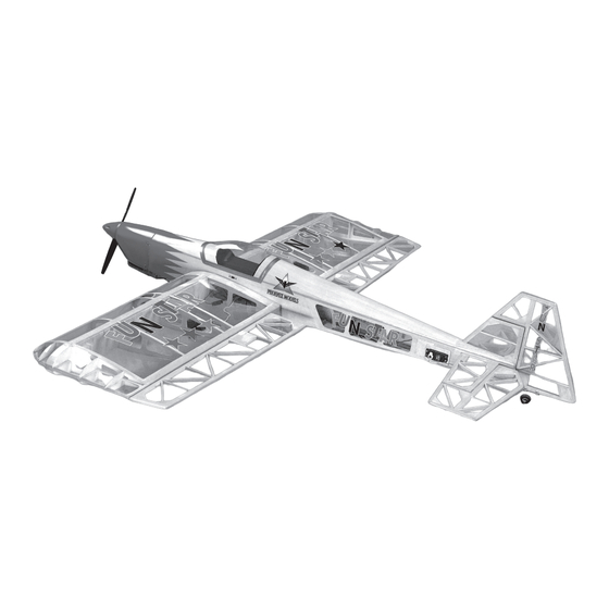
FUN STAR
Instruction Manual
SPECIFICATION
Wingspan
Length
Engine
Radio
4channel Servos 5 standard
1340 mm (52.7 inches)
1310 mm (51.5 inches)
40~.46 two stroke
48~.53 four stroke
Items required to complete and fly the Funstar
.40~.46 Two Stroke 48~.53 Four Stroke Model Engine and Propeller
4 Channel Proportional Radio Control System with five servos
Model Engine Fuel, Model Engine Starter and Glow Plug Battery
Hand Tools and Adhesives
Made in Vietnam
Advertisement

Related Manuals for arf Fan Star


Summary of Contents for arf Fan Star
-
Page 1: Instruction Manual
FUN STAR Instruction Manual SPECIFICATION Wingspan 1340 mm (52.7 inches) Length 1310 mm (51.5 inches) Items required to complete and fly the Funstar Engine 40~.46 two stroke .40~.46 Two Stroke 48~.53 Four Stroke Model Engine and Propeller 4 Channel Proportional Radio Control System with five servos 48~.53 four stroke Model Engine Fuel, Model Engine Starter and Glow Plug Battery Radio... -
Page 3: Kit Contents
KIT CONTENTS: We have organized the parts as they come out of the box for better identification during assembly. We recommend that you regroup the parts in the same manner. This will ensure you have all of parts required before you begin assembly. KIT CONTENTS AIRFRAME ASSEMBLIES MOTOR MOUNT ASSEMBLY... - Page 4 FINISHING THE WINGS PICTURE 01 PICTURE 02 PICTURE 03 MAKE TWO HOLES CUT AWAY THE COVERING USE A SMALL WEIGHT... 1.1 Make two holes on the top 1.2 Cut away the covering 1.3 Use a small weight of the wing for the aileron from servo aileron (weighted fuel pick-up) servo wires.
- Page 5 PICTURE 09 PICTURE 10 Using pliers, bend the wire in an L shape and connect it to the servo arm. Install the snap keeper to secure the wire to the servo arm. Using wire cutters, cut off the excess wire. When fitting any of the clevises to the pushrod ensure that the INSTALL THE AILERON...
- Page 6 PICTURE 15 PICTURE 16 2.4 Use masking tape to protect the covering from glue before using 30 minute epoxy to glue the horizontal stab into place. Be sure that the horizontal stab is fitted accurately before the glue has cured and remove CAREFULLY CUT AWAY THE GLUE THE TAILPLANE the masking tape as soon...
- Page 7 FITTING THE LANDING GEAR PICTURE 21 PICTURE 22 3.1 Prepare the accessories for landing gear. 3.2 Install the wheel as shown. 3.3 Install the landing gear onto the fuselage as shown. ACCESSORIES FOR LANDING THE WHEEL 3.4 Install the tail wheel onto GEAR the fuselage as shown.
- Page 8 FITTING THE ELEVATOR HORN AND THE RUDDER HORN PICTURE 26 PICTURE 27 PICTURE 28 CUT AWAY THE COVERING PREPARE THE SERVO OF INSTALL THE SERVO OF RUDDER RUDDER 5.1 There are precut rudder 5.2 Install the rubber servo each servo and position and elevator servo grommets and brass each into the plywood tray.
- Page 9 INSTALLING THE SERVO AND CONNECTING THE THROTTLE 6.2 Install the throttle servo servo arm angled back PICTURE 32 towards the rear of the grommets and brass Throttle servo model, at about 45degree eyelets supplied with your Antenna exit from centre line of the radio equipment.
-
Page 10: Metric Conversions
RADIO CONTROL AND CONTROL SURFACE THROWS ELEVATOR : 25mm up 10 We recommend the 25mm down following control surface RUDDER 50mm right throws: 50mm left AILERON 20mm up 20mm down BALANCE YOUR MODEL 11.1 This section is very use masking tape to mark important and must not be the balance point. - Page 11 I/C FLIGHT WARNINGS Page 9...
- Page 12 I/C FLIGHT GUIDELINES Page 10...
Need help?
Do you have a question about the Fan Star and is the answer not in the manual?
Questions and answers