Table of Contents
Advertisement
Quick Links
Advertisement
Table of Contents

Related Manuals for Motorola MC919Z


Summary of Contents for Motorola MC919Z
- Page 1 MC919Z RFID Mobile Computer Integrator Guide Supplement...
- Page 3 MC919Z Integrator Guide Supplement 72E-157455-02 Rev A March 2015...
- Page 4 MC919Z Integrator Guide Supplement © 2015 Symbol Technologies, Inc. No part of this publication may be reproduced or used in any form, or by any electrical or mechanical means, without permission in writing from Zebra. This includes electronic or mechanical means, such as photocopying, recording, or information storage and retrieval systems.
-
Page 5: Revision History
Revision History Changes to the original manual are listed below: Change Date Description Rev A 02/2012 Initial release. Rev A 3/2015 Zebra Rebranding... - Page 6 MC919Z Integrator Guide Supplement...
-
Page 7: Table Of Contents
Chapter 1: Getting Started Introduction ........................1-1 RFID Technology Overview ..................1-1 RFID Components ....................1-2 MC919Z RFID Mobile Computer .................. 1-3 MC919Z Parts ....................... 1-4 MC919Z LED Indicators ..................1-5 Reading Tags ....................... 1-5 Chapter 2: Updating the RFID Mobile Computer Introduction ........................ - Page 8 MC919Z Integrator Guide Supplement Chapter 3: MobileRFID Functionality Introduction ........................3-1 MobileRFID Icons ......................3-2 MobileRFID Menu ......................3-3 Configure Region ....................3-4 Configure RFID ....................... 3-7 Version Information ....................3-8 Run/Stop RFID ......................3-9 Chapter 4: RFID Sample Application Introduction ........................
- Page 9 Table of Contents Appendix A: Technical Specifications MC919Z Specifications ....................A-1 Decode Zones ......................A-5 SE960 Standard Range Laser Decode Zones ............A-5 SE1524 Long Range Laser Decode Zones ............A-7 SE4500 Standard Range Imager Decode Zones ........... A-9 Mobile Computer Pin-Outs ..................A-13 Accessory Specifications ....................
- Page 10 MC919Z Integrator Guide Supplement...
-
Page 11: About This Guide
This MC919Z RFID Integrator Guide Supplement provides the unique set up and operating procedures for the MC919Z RFID mobile computers. This guide is intended as a supplement to the MC9190-G Integrator Guide, p/n 72E-140937-xx. Procedures common to MC9100 products are addressed in the MC9190-G Integrator Guide. -
Page 12: Chapter Descriptions
RFID APIs. Notational Conventions The following conventions are used in this document: • “Mobile computer” refers to the MC919Z hand-held computer. • Italics are used to highlight the following: • Chapters and sections in this guide •... -
Page 13: Related Documents And Software
About This Guide Related Documents and Software The following documents provide more information about the MC919Z. • MC919Z Quick Start Guide, p/n 72-152191-xx • MC919Z Regulatory Guide, p/n 72-157453-xx • MC9190-G User Guide, p/n 72E-140936-xx • MC9190-G Integrator Guide, p/n 72E-140937-xx •... - Page 14 MC919Z Integrator Guide Supplement...
-
Page 15: Chapter 1 Getting Started
Chapter 1 Getting Started Introduction This chapter provides an overview of RFID technology and components, and describes the MC919Z RFID mobile computer and product features. RFID Technology Overview RFID (Radio Frequency Identification) is an advanced automatic identification (Auto ID) technology that uses radio frequency signals to identify tagged items. -
Page 16: Rfid Components
The radio module communicates with the tags and transfers the data to a host computer. It also provides features such as filtering, CRC check, and tag writing. The MC919Z RFID mobile computer supports standard RFID tags as described by EPCGlobal... -
Page 17: Mc919Z Rfid Mobile Computer
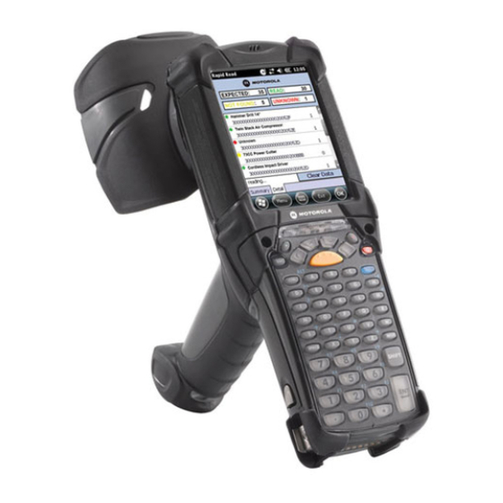
1 - 3 MC919Z RFID Mobile Computer The Zebra MC919Z RFID mobile computer includes an intelligent C1G2 UHF RFID reader with RFID read performance that provides real-time, seamless EPC-compliant tag processing. MC919Z RFID mobile computers are designed for back room inventory management, manufacturing floors, inside/outside loading dock and asset tracking applications, and can host third-party, customer-driven embedded applications. -
Page 18: Mc919Z Parts
1 - 4 MC919Z Integrator Guide Supplement MC919Z Parts Microphone Headphone Jack Indicator LED Bar Touch Screen Power Scan Button Battery Trigger Keypad Battery Release Handstrap (1 of 2) MC919Z Parts Figure 1-3... -
Page 19: Mc919Z Led Indicators
Reading Tags To read RFID tags: Remove the MC919Z from AC power and ensure the LLRP icon is green. NOTE When connected to power, the mobile computer cannot read RFID tags. Use an RFID reader application to enable tag reading. For a sample application, tap on icon RFID Demo in the start menu, or browse to the MC919Z Application directory and select CS_RFID3Sample6.exe. - Page 20 1 - 6 MC919Z Integrator Guide Supplement...
-
Page 21: Chapter 2 Updating The Rfid Mobile Computer
Chapter 2 Updating the RFID Mobile Computer Introduction This chapter describes how to update the device image and radio firmware. Updating the Device Image Windows Mobile contains an Image Update feature that updates all operating system components. Zebra distributes all updates as update packages on the Support Central Web Site http://www.zebra.com/support. These packages contain either partial or complete updates for the operating system. -
Page 22: Updating The Rfid Firmware
2 - 2 MC919Z Integrator Guide Supplement On the mobile computer, navigate to the \Storage Card folder and tap the program STARTUPDLDR.EXE. The update takes approximately 10 minutes. Do not remove AC power during this time. Copy MCRFIDInstall_x.x.x.CAB into the \Storage Card folder on the mobile computer. -
Page 23: Chapter 3 Mobilerfid Functionality
Chapter 3 MobileRFID Functionality Introduction MobileRFID is an RFID server application that runs in the background on the mobile computer. The MobileRFID icon appears in the system tray. This chapter includes information on using and configuring MobileRFID. MobileRFID Icon Figure 3-1... -
Page 24: Mobilerfid Icons
3 - 2 MC919Z Integrator Guide Supplement MobileRFID Icons The MobileRFID icon indicates RFID radio status as described in Table 3-1. MobileRFID Icon Indicators Table 3-1 Icon Indication RFID running, radio on. RFID running, radio off. RFID stopped (radio not found/battery critical/stopped from user interface). -
Page 25: Mobilerfid Menu
MobileRFID Functionality 3 - 3 MobileRFID Menu If using RFID as the Windows default home screen, tap the RFID panel, then tap the Settings button. MobileRFID Home Window and Settings Window Figure 3-2 If not using RFID as the Windows default home screen, tap the MobileRFID icon in the system tray. A menu appears. -
Page 26: Configure Region
3 - 4 MC919Z Integrator Guide Supplement Configure Region Upon Startup After upgrading the mobile computer, the following window appears on startup. Country Not Set Window Figure 3-4 Tap ok. When no country is selected, the Region Configuration window appears. - Page 27 MobileRFID Functionality 3 - 5 Select the Region of Operation and Communication Standard as allowed by the regulatory standards of that country/region from the drop-down menus. The following warning message appears. Region Selection Warning Message Figure 3-6 Tap Yes to confirm. A window appears indicating success. Region Selection Success Window Figure 3-7...
- Page 28 3 - 6 MC919Z Integrator Guide Supplement After Startup If not done at startup, set the regulatory region as follows: Invoke the MobileRFID menu, then tap Configure Region. In the Region Configuration window, select a region from the Region of Operation drop-down menu.
-
Page 29: Configure Rfid
MobileRFID Functionality 3 - 7 Configure RFID RFID is in Server Mode by default. To configure RFID to operate in Client Mode: Invoke the MobileRFID menu, then tap Configure RFID. RFID Configuration Window Figure 3-10 Select the Client Mode check box. In the LLRP Port field, enter the port number on which the server waits for the RFID client to communicate. -
Page 30: Version Information
3 - 8 MC919Z Integrator Guide Supplement Version Information To view software version information for the RFID application, invoke the MobileRFID menu, then tap About. About MobileRFID Window Figure 3-11 This window displays the MobileRFID application version, radio library version, radio firmware version, and radio OEM data version. -
Page 31: Run/Stop Rfid
MobileRFID Functionality 3 - 9 Run/Stop RFID To stop RFID service, tap Stop in MobileRFID menu. RFID Stopped Figure 3-12 To restart RFID, tap Run in MobileRFID menu. - Page 32 3 - 10 MC919Z Integrator Guide Supplement...
-
Page 33: Chapter 4 Rfid Sample Application
Chapter 4 RFID Sample Application Introduction The RFID Application CS_RFID3Sample6.exe provides an overview of how the application works and assists application developers in developing custom applications. The mobile computer can read, write, lock, kill, and program Gen2 tags. Each tag contains the EPC number (64 or 96 bits), CRC, and kill code. -
Page 34: Launching The Rfid Sample Application
4 - 2 MC919Z Integrator Guide Supplement Launching the RFID Sample Application Select RFID Demo in the Start menu to start the RFID sample application. RFID Demo Icon Figure 4-1 RFID Sample Application Window Figure 4-2 In the sample application window: •... -
Page 35: Connection
RFID Sample Application 4 - 3 Connection Tap Connection to display the reader IP and port number. Select Disconnect to disconnect the reader. Connection Window Figure 4-3... -
Page 36: Capabilities
4 - 4 MC919Z Integrator Guide Supplement Capabilities Select Menu > Capabilities to view the capabilities of the connected reader. Capabilities Window Figure 4-4... -
Page 37: Configuration Menu Options
RFID Sample Application 4 - 5 Configuration Menu Options The Configuration Menu includes the following options: • Tag Storage Settings • Antenna • RF Mode • Singulation • Power On/Off Radio • Reset to Factory Defaults Tag Storage Settings Select Menu > Config > Tag Storage Settings to view/configure tag storage settings. Tag Storage Settings Window Figure 4-5 The Tag Storage Settings window includes the following fields:... -
Page 38: Antenna
4 - 6 MC919Z Integrator Guide Supplement Antenna Select Menu > Config > Antenna to view/configure the antenna. Antenna Configuration Window Figure 4-6 The Antenna Configuration window includes the following fields: • Antenna ID - Select an antenna ID to update the configuration values in the other fields. -
Page 39: Rf Mode
RFID Sample Application 4 - 7 RF Mode Select Menu > Config > RF Mode to view/configure the RF mode for each antenna. RF Mode Window Figure 4-7 The RF Mode window includes the following fields: • Antenna ID - Select an antenna ID to update the configuration values in the other fields. •... -
Page 40: Singulation
4 - 8 MC919Z Integrator Guide Supplement Singulation Select Menu > Config > Singulation to view/configure the singulation control settings for each antenna. Singulation Control Settings Window Figure 4-8 This Singulation settings window includes the following fields: • Antenna ID - Select an antenna ID to update the configuration values in the other fields. -
Page 41: Power On/Off Radio
RFID Sample Application 4 - 9 Power On/Off Radio Select Menu > Config > Power On/Off Radio to change the power settings of the RFID radio. Radio Power Settings Menu Figure 4-9 Reset to Factory Default Select Menu > Config > Reset to Factory Default to restore the default reader configuration. -
Page 42: Operations Menu Options
4 - 10 MC919Z Integrator Guide Supplement Operations Menu Options The Operations Menu includes the following options: • Antenna Info • Filter • Access • Triggers Antenna Info Select Menu > Operations > Antenna Info to view/configure the list of antennas that can be used for inventory/access operations. -
Page 43: Filter
RFID Sample Application 4 - 11 Filter Select Menu > Operations > Filter to view/configure the following filters: • Pre-Filter • Post-Filter • Access-Filter Pre-Filter Select Menu > Operations > Filter > Pre-Filter to view/configure pre-filters. PreFilter Window Figure 4-11 This Pre-Filter window includes the following fields: •... - Page 44 4 - 12 MC919Z Integrator Guide Supplement Post-Filter Select Menu > Operations > Filter > Post-Filter to view/configure post-filters. Post-Filter Window Figure 4-12 This Post-Filter window includes the following fields: • Memory Bank - Memory bank on which the filter is applied.
- Page 45 RFID Sample Application 4 - 13 Access-Filter Select Menu > Operations > Filter > Access-Filter to view/configure the access-filters. Access-Filter Window Figure 4-13 This Access-Filter window includes the following fields: • Memory Bank - Memory bank on which the filter is applied. •...
-
Page 46: Access
4 - 14 MC919Z Integrator Guide Supplement Access Select Menu > Operations > Access to perform the following access operations. Access Menu Figure 4-14 The Access menu includes the following options: • Read • Write • Lock • Kill •... - Page 47 RFID Sample Application 4 - 15 To perform an access option on a single tag, right-click the tag in the list of read tags on the main window to invoke the tag’s context menu. Tag Context Menu Figure 4-15 Access Operation Windows The Access Operation windows include the following fields.
- Page 48 4 - 16 MC919Z Integrator Guide Supplement Read Access Operation Window Figure 4-16 Write / Block-Write Access Operation Window Figure 4-17...
- Page 49 RFID Sample Application 4 - 17 Lock Access Operation Window Figure 4-18 Kill Access Operation Window Figure 4-19...
- Page 50 4 - 18 MC919Z Integrator Guide Supplement Block Erase Access Operation Window Figure 4-20...
-
Page 51: Triggers
RFID Sample Application 4 - 19 Triggers Select Menu > Operations > Trigger to view/configure the trigger. Start Trigger - Periodic Window Figure 4-21 Start Trigger The Trigger Type in the Start Trigger window includes the following fields: • Immediate - Start operation immediately. •... - Page 52 4 - 20 MC919Z Integrator Guide Supplement Start Trigger - Periodic Window Figure 4-22 Start Trigger - GPI Window Figure 4-23...
- Page 53 RFID Sample Application 4 - 21 Start Trigger - Handheld Trigger Window Figure 4-24...
- Page 54 4 - 22 MC919Z Integrator Guide Supplement Stop Trigger Stop Trigger - GPI with Timeout Window Figure 4-25 The Trigger Type in the Stop Trigger window includes the following fields: • Immediate - Stop operation immediately. • Duration - Stop operation after a duration specified in milliseconds.
- Page 55 RFID Sample Application 4 - 23 Stop Trigger - GPI with Timeout Figure 4-26 Stop Trigger - Tag Observation with Timeout Window Figure 4-27...
- Page 56 4 - 24 MC919Z Integrator Guide Supplement Stop Trigger - N Attempts with Timeout Window Figure 4-28 Stop Trigger - Handheld Trigger with Timeout Window Figure 4-29...
- Page 57 RFID Sample Application 4 - 25 Report Trigger Report Trigger Window Figure 4-30 Report settings are applicable when tag options are checked in the main window of the demo application. The following event generations are controlled by criteria settings in Report Trigger. The events associated with a tag are as follows: •...
-
Page 58: Management Menu Options
4 - 26 MC919Z Integrator Guide Supplement Management Menu Options Management options are not applicable for handheld readers. Help Menu Select Menu > Help to display the version information. The version numbers displayed in this window are examples. Actual version numbers are based on the versions of the files on the device. -
Page 59: Chapter 5 Tag Locator
Chapter 5 Tag Locator Introduction Use Tag Locator to detect the location of a tag. By providing the TagID of an item, this application can find the relative position of the tag with respect to the mobile computer. Move the mobile computer back and forth to obtain the location of the tag as indicated by the beep frequency and a vertical progress bar showing the relative position of the tag. -
Page 60: Using Tag Locator
5 - 2 MC919Z Integrator Guide Supplement Using Tag Locator To use the Tag Locator application: Tap Tag Locator in the Application folder on the mobile computer to open the Tag Locator application. Tag Locator Figure 5-1 Enter the tag ID in one of three ways: •... -
Page 61: Locating Tags Using A .Csv File
Tag Locator 5 - 3 Locating Tags Using a .csv File Select the Import Tags button to import a list of saved tags from a .csv file. The following window appears. Opening a .csv File Figure 5-2 Select the desired .csv file to import the tags to the list. Tag List Figure 5-3 Select a tag from the list to search. - Page 62 5 - 4 MC919Z Integrator Guide Supplement Select the Locate button or press and hold the trigger. Move the mobile computer in all directions to get the relative position of the tag, indicated by a beep, the vertical progress bar, or both.
-
Page 63: Chapter 6: Troubleshooting
Battery not installed Ensure battery is installed properly. properly. System crash. Perform a warm boot. If the MC919Z still does not turn on, perform a cold boot. Rechargeable battery Battery failed. Replace battery. If the MC919Z still does not operate, try a warm did not charge. - Page 64 30 sec., 1, 2, 3, 4, 5 or 6 minutes. If the MC919Z is running on external power, this period can be set to 1, 2, 3, 5, 10, 15 and 30 minutes.
-
Page 65: Bluetooth Connection
Distance between Ensure MC919Z is within proper scanning range. exit window and bar code is incorrect. MC919Z is not Ensure the MC919Z is programmed to accept the type of bar programmed for the code being scanned. bar code. MC919Z is not... -
Page 66: Four Slot Charge Only Cradle
LED does not power. power. light. MC919Z is not seated Ensure the battery is properly installed in the MC919Z, and correctly in the cradle. re-seat the MC919Z in the cradle. The battery is not properly installed in the MC919Z. - Page 67 Battery is not MC919Z removed from Replace the MC919Z into the cradle. It can take up to four hours recharging. the cradle too soon. to recharge a completely depleted battery pack if MC919Z is suspended or longer if the MC919Z is on.
-
Page 68: Four Slot Spare Battery Charger
Ensure cradle is receiving power. Ensure MC919Z is seated is not charging. from cradle or cradle was correctly. Confirm that the battery is charging. If a MC919Z battery is unplugged from AC fully depleted, it can take up to four hours to fully recharge a battery power too soon. -
Page 69: Cable Adapter Module
Ensure CAM is receiving power. Ensure MC919Z is attached is not charging. from CAM or CAM was correctly. Confirm that the battery is charging. If a MC919Z battery is unplugged from AC fully depleted, it can take up to four hours to fully recharge a battery power too soon. -
Page 70: Magnetic Stripe Reader
Ensure MSR is receiving power. Ensure MC919Z is attached is not charging. from MSR or MSR was correctly. Confirm that the battery is charging. If a MC919Z battery is unplugged from AC fully depleted, it can take up to four hours to fully recharge a battery power too soon. -
Page 71: Modem Module
System Administrator. MC919Z’s battery is low or Install a charged battery in the MC919Z, or use an external DC discharged, which shuts power adapter to recharge the battery. off power to the modem. - Page 72 Incorrect server phone Verify the connection phone number in the Connecting window. number. Pulse dialing not Use a connection within a tone-dialing system. supported for country. The Connection Manager Warm boot the MC919Z and confirm the connection settings. routes are incorrect.
-
Page 73: Appendix A Technical Specifications
Appendix A Technical Specifications MC919Z Specifications The following table summarizes the MC919Z’s technical specifications. Technical Specifications Table A-1 Item Description Physical and Environmental Characteristics Dimensions 10.83 in. L x 4.7 in. W x 7.6 in. H 27.50 cm L x 11.95 cm H x 19.3 cm H Weight (includes Lorax: 1077 g (38 oz.) - Page 74 A - 2 MC919Z Integrator Guide Supplement Technical Specifications (Continued) Table A-1 Item Description Data Capture SE960: 1D standard range scan engine. Options SE1524-ER: 1D extended range scan engine reads up to 45 ft./13.72 m away. SE4500-SR: Omnidirectional 1D/2D imaging engine reads 1D and 2D symbols.
- Page 75 Technical Specifications A - 3 Technical Specifications (Continued) Table A-1 Item Description WLAN Wireless Data Communications WLAN radio 802.11a/b/g. Note: 802.11a not available in Thailand. Output Power 100mW U.S. and International Data Rate 802.11a: up to 54Mb per second 802.11b: up to 11Mb per second 802.11g: up to 54Mb per second Frequency All country dependent: 802.11a - 5 GHz;...
- Page 76 A - 4 MC919Z Integrator Guide Supplement Data Capture Options Table A-2 Item Description Laser Decode Capability Code 39 Code 128 Code 93 Codabar Code 11 Discrete 2 of 5 Interleaved 2 of 5 EAN-8 EAN-13 UPCA UPCE UPC/EAN supplementals...
-
Page 77: Decode Zones
Technical Specifications A - 5 Decode Zones SE960 Standard Range Laser Decode Zones Figure A-1 shows the decode zone for the SE960 scan engine. The figures are typical values. Table A-3 lists the typical distances for selected bar code densities. The minimum element width (or “symbol density”) is the width in mils of the narrowest element (bar or space) in the symbol. - Page 78 A - 6 MC919Z Integrator Guide Supplement SE960 Decode Distances Table A-3 Symbol Density/ Typical Working Ranges Bar Code Content/ Bar Code Type/ Note 1 Contrast W-N Ratio Near 5.0 mil 1234 1.2 in 7.7 in Code 128 80% MRD 3.05 cm...
-
Page 79: Se1524 Long Range Laser Decode Zones
Technical Specifications A - 7 SE1524 Long Range Laser Decode Zones Typical decode ranges are shown in Figure A-2. Table A-4 on page A-8 lists the typical distances for the SE1524 for selected bar code densities. The minimum element width (or “symbol density”) is the width in mils of the narrowest element (bar or space) in the symbol. - Page 80 A - 8 MC919Z Integrator Guide Supplement SE 1524 Decode Distances Table A-4 Symbol Density/ Typical Working Ranges Bar Code Content/ p/n / Bar Code Type/ Note 1 Contrast W-N Ratio Near 7.5 mil ABCDEF 2.0 in 22.0 in 64-17452-01 80% MRD 5.08 cm...
-
Page 81: Se4500 Standard Range Imager Decode Zones
Technical Specifications A - 9 SE4500 Standard Range Imager Decode Zones SE4500-SR Figure A-3 shows the decode zone for the SE4500-SR. Typical values appear. Table A-3 lists the typical distances for selected bar code densities. The minimum element width (or “symbol density”) is the width in mils of the narrowest element (bar or space) in the symbol. - Page 82 A - 10 MC919Z Integrator Guide Supplement SE4500-SR Decode Distances Table A-5 Typical Working Ranges Symbol Density/ Bar Code Content/ Note 2 Bar Code Type Contrast Near 5.0 mil ABCDEFGH 2.1 in 7.5 in Code 39 80% MRD 5.33 cm 19.05 cm...
- Page 83 Technical Specifications A - 11 SE4500-HD Figure A-4 shows the decode zone for the SE4500-HD. Typical values appear. Table A-6 lists the typical distances for selected bar code densities. The minimum element width (or “symbol density”) is the width in mils of the narrowest element (bar or space) in the symbol.
- Page 84 A - 12 MC919Z Integrator Guide Supplement SE4500-HD Decode Distances Table A-6 Typical Working Ranges Symbol Density/ Bar Code Content/ Note 2 Bar Code Type Contrast Near 3.0 mil 80% MRD 1.6 in 3.8 in Code 39 4.06 cm 9.65 cm 4.0 mil...
-
Page 85: Mobile Computer Pin-Outs
Technical Specifications A - 13 Mobile Computer Pin-Outs Pin Locations m Figure A-5 Pin-Outs Table A-7 PIN Number Signal Name Function USB_GND USB_D_PLUS RS232C RS232C RS232C RS232C RS232C Ground, 2.5A max. RS232C CRADLE_DET Grounded by cradle when in cradle RS232C Not connected Not connected POWER_IN... -
Page 86: Accessory Specifications
A - 14 MC919Z Integrator Guide Supplement Accessory Specifications Single Slot Serial/USB Cradle Single SLot Serial/USB Cradle Technical Specifications Table A-8 Feature Description Dimensions Height: 13.02 cm (5.13 in.) Width: 15.24 cm (6.0 in.) Depth: 15.24 cm (6.0 in.) Input Power... -
Page 87: Four Slot Charge Only Cradle
Technical Specifications A - 15 Four Slot Ethernet Cradle Technical Specifications (Continued) Table A-9 Feature Description Humidity 5% to 95% non-condensing Drop 76.2 cm (30.0 in.) drops to vinyl tiled concrete at room temperature Electrostatic Discharge (ESD) +/- 15 kV air +/- 8 kV contact Four Slot Charge Only Cradle Four Slot Charge Only Cradle Technical Specifications... -
Page 88: Magnetic Stripe Reader
A - 16 MC919Z Integrator Guide Supplement Four Slot Battery Charger Technical Specifications (Continued) Table A-11 Feature Description Humidity 5% to 95% non-condensing Drop 76.2 cm (30.0 in.) drops to vinyl tiled concrete at room temperature Electrostatic Discharge (ESD) +/- 15 kV air... -
Page 89: Accessory Cam And Msr Pin-Outs
Technical Specifications A - 17 Accessory CAM and MSR Pin-Outs CAM and MSR Serial Connector Figure A-7 CAM and MSR Serial Connector Pin-outs Table A-12 Signal USB_5V_DET USB_D_MINUS USB_D_PLUS PWR_EXT_OUT CRADLE_DET*... - Page 90 A - 18 MC919Z Integrator Guide Supplement...
-
Page 91: Appendix B Rfid Apis
Appendix B RFID APIs RFID APIs are available in C, .NET, and Java. For information on supported RFID APIs, refer to the Enterprise Mobility Developer Kit (EMDK), available at http://www.zebra.com/support For C, refer to the EMDK for C v2.1 or later. For .Net, refer to the EMDK for .NET v2.2 or later. - Page 92 B - 2 MC919Z Integrator Guide Supplement...
- Page 93 Index display ........A-1 drop specification ......A-2 activesync .
- Page 94 Index - 2 MC919Z Integrator Guide Supplement MobileRFID ....... . 3-1 activesync .
- Page 96 Zebra Technologies Corporation Lincolnshire, IL U.S.A. http://www.zebra.com Zebra and the Zebra head graphic are registered trademarks of ZIH Corp. The Symbol logo is a registered trademark of Symbol Technologies, Inc., a Zebra Technologies company. © 2015 Symbol Technologies, Inc. 72E-157455-02 Revision A - March 2015...
Need help?
Do you have a question about the MC919Z and is the answer not in the manual?
Questions and answers