Table of Contents
Advertisement
Advertisement
Chapters
Table of Contents

Related Manuals for Siemens 7SG11


Summary of Contents for Siemens 7SG11
- Page 1 Reyrolle Protection Devices 7SG11 Argus 1-6 Overcurrent Relay Answers for energy...
-
Page 2: Table Of Contents
Limited. No part of this document shall be reproduced or modified or stored in another form, in any data retrieval system, without the permission of Siemens Protection Devices Limited, nor shall any model or article be reproduced from this document unless Siemens Protection Devices Limited consent. - Page 3 Siemens Protection Devices Limited. No part of this document shall be reproduced or modified or stored in another form, in any data retrieval system, without the permission of Siemens Protection Devices Limited, nor shall any model or article be reproduced from this document unless Siemens Protection Devices Limited consent.
- Page 4 SMA fibre-optic connectors optimised for 62.5/125 m glass fibre, or SMA fibre-optic connectors optimised for 1 mm plastic fibre. RS 485 Electrical communications All relays are 1A/5A rated unless otherwise stated in the following table. ©2013 Siemens Protection Devices Limited Page 2 of 16...
- Page 5 1 binary input and 110 V application, order resistor box VCE:2512H10066 in addition for 1 binary input and 220 V application, order resistor box VCE:2512H10068 in addition Refer to website for application note about ESI48-4 compliance. ©2013 Siemens Protection Devices Limited Page 3 of 16...
- Page 6 5 binary inputs and 220 V application, order resistor box VCE:2512H10067 in addition for 9 binary inputs and 220 V application, order two resistor boxes VCE:2512H10067 in addition Refer to website for application note about ESI48-4 compliance. ©2013 Siemens Protection Devices Limited Page 4 of 16...
- Page 7 5 binary inputs and 220 V application, order resistor box VCE:2512H10067 in addition for 9 binary inputs and 220 V application, order two resistor boxes VCE:2512H10067 in addition Refer to website for application note about ESI48-4 compliance ©2013 Siemens Protection Devices Limited Page 5 of 16...
- Page 8 5 binary inputs and 110 V application, order resistor box VCE:2512H10065 in addition for 5 binary inputs and 220 V application, order resistor box VCE:2512H10067 in addition Refer to website for application note about ESI48-4 compliance ©2013 Siemens Protection Devices Limited Page 6 of 16...
- Page 9 1 binary input and 110 V application, order resistor box VCE:2512H10066 in addition for 1 binary input and 220 V application, order resistor box VCE:2512H10068 in addition Refer to website for application note about ESI48-4 compliance ©2013 Siemens Protection Devices Limited Page 7 of 16...
- Page 10 5 binary inputs and 220 V application, order resistor box VCE:2512H10067 in addition for 9 binary inputs and 220 V application, order two resistor boxes VCE:2512H10067 in addition Refer to website for application note about ESI48-4 compliance ©2013 Siemens Protection Devices Limited Page 8 of 16...
- Page 11 5 binary inputs and 220 V application, order resistor box VCE:2512H10067 in addition for 9 binary inputs and 220 V application, order two resistor boxes VCE:2512H10067 in addition Refer to website for application note about ESI48-4 compliance ©2013 Siemens Protection Devices Limited Page 9 of 16...
- Page 12 5 binary inputs and 220 V application, order resistor box VCE:2512H10067 in addition for 9 binary inputs and 220 V application, order two resistor boxes VCE:2512H10067 in addition Refer to website for application note about ESI48-4 compliance ©2013 Siemens Protection Devices Limited Page 10 of 16...
- Page 13 9 binary inputs and 110 V application, order resistor box VCE:2512H10064 in addition for 9 binary inputs and 220 V application, order two resistor boxes VCE:2512H10067 in addition Refer to website for application note about ESI48-4 compliance ©2013 Siemens Protection Devices Limited Page 11 of 16...
- Page 14 9 binary inputs and 110 V application, order resistor box VCE:2512H10064 in addition for 9 binary inputs and 220 V application, order two resistor boxes VCE:2512H10067 in addition Refer to website for application note about ESI48-4 compliance ©2013 Siemens Protection Devices Limited Page 12 of 16...
- Page 15 9 binary inputs and 110 V application, order resistor box VCE:2512H10064 in addition for 9 binary inputs and 220 V application, order two resistor boxes VCE:2512H10067 in addition Refer to website for application note about ESI48-4 compliance ©2013 Siemens Protection Devices Limited Page 13 of 16...
- Page 16 DCD425B DCD426B 2 phase-fault, earth-fault and SEF AG1-423 AG1-424 DCD421C DCD423C D C D 4 2 4 D C D 4 2 5 D C D 4 2 6 7 OR ©2013 Siemens Protection Devices Limited Page 14 of 16...
- Page 17 GAF911C GAF913C GAF914C overcurrent AG6-403 AG6-404 3 directional phase-fault and SEF protection & 7 OR GAF921C GAF923C GAF924C autoreclose AG6-405 AG6-406 3 phase-fault and dir’n. earth-fault 7 OR GAF931C GAF933C GAF934C ©2013 Siemens Protection Devices Limited Page 15 of 16...
-
Page 18: Document Set
Communication Interface P20007 Diagrams and Parameters Variants Settings IEC 60870-5-103 Definitions Application Diagrams P20008 Argus 1 P20009 Argus 2 P20010 Argus 4 P20011 Argus 6 P1001 P300013 Argus Overcurrent Doc Structure ©2013 Siemens Protection Devices Limited Page 16 of 16... -
Page 19: User Manual
Limited. No part of this document shall be reproduced or modified or stored in another form, in any data retrieval system, without the permission of Siemens Protection Devices Limited, nor shall any model or article be reproduced from this document unless Siemens Protection Devices Limited consent. - Page 20 7SG11 Argus User Manual Contents Section 1: Relay Description ..........................4 1.1 Overview ............................4 1.2 Hardware ............................4 1.3 Functionality ............................6 Section 2: Operation Guide ..........................12 2.1 User Interface Operation........................12 2.2 Operation using Reydisp Evolution (IEC 60870-5-103 comms only)...........15 Section 3: Installation............................16 3.1 Unpacking, Storage and Handling ....................16...
- Page 21 7SG11 Argus User Manual List of Figures Figure 1-1 Overcurrent Characteristics ......................7 Figure 2-1 Menu Structure for Argus 1, 2, 4 and 6 Relays ................13 Figure 4-1 Directional Earth Fault Boundary System Angles.................23 Figure 4-2 Directional Phase Fault Boundary System Angles ...............23 Figure 4-3 Secondary Injection Test Circuit....................33...
-
Page 22: Section 1: Relay Description
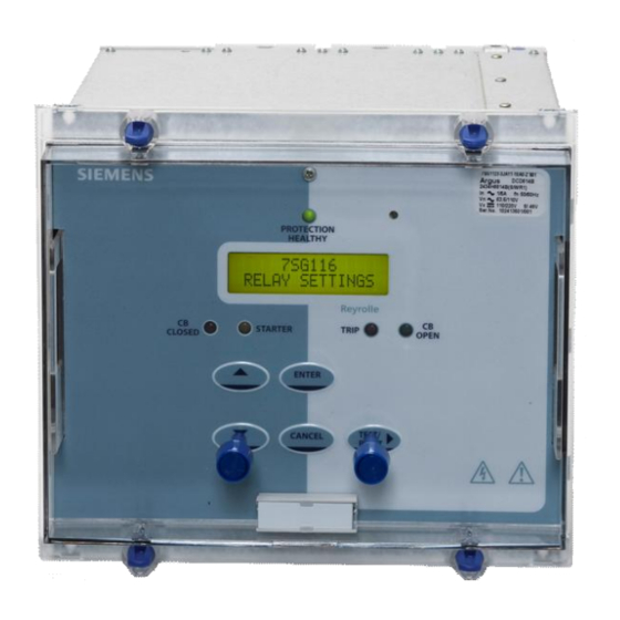
7SG11 Argus User Manual Section 1: Relay Description 1.1 Overview The Argus range of overcurrent protection combines the power and flexibility of microprocessor technology with decades of experience in the field of overcurrent protection and auto-reclose. A wide range of protection elements are supplemented by advanced features such as control, metering, data storage and fibre-optic based communications. - Page 23 7SG11 Argus User Manual Liquid Crystal Display A 2 line, 16 character backlit liquid crystal display (LCD) is used to present settings, instruments and fault data in a textual format. The display backlighting is turned off to conserve power if no pushbuttons are pressed for 5 minutes.
-
Page 24: Functionality
7SG11 Argus User Manual 9 status inputs, 7 output relays (3 changeover, 4 normally open) Single pole Argus relays are only available with 1 status input and 7 output relays. Status Inputs Status inputs can be programmed to perform one or more of the following functions:... -
Page 25: Figure 1-1 Overcurrent Characteristics
7SG11 Argus User Manual 1.3.1.1 Phase-fault and Earth-fault Overcurrent Phase-fault and earth-fault inputs each have four independent overcurrent elements. Each has a current setting and timing characteristic as illustrated in Figure 1-1. The principal overcurrent element is selectable between IDMTL (inverse definite minimum time lag) and DTL (definite time lag) characteristics. - Page 26 7SG11 Argus User Manual 1.3.1.4 Voltage Protection Certain Argus 2 models only. A three-phase voltage element with definite time delay is provided which can be used to provide a trip or alarm output, or can be set to block any of the overcurrent elements. The element can be set to undervoltage or overvoltage with variable hysteresis.
- Page 27 7SG11 Argus User Manual Available Instruments Primary current – RMS values on a phase-by-phase basis, indicated by upper case letters, e.g. A, B, C, E, SE (sensitive earth) Secondary current – RMS values on a phase-by-phase basis, indicated by lower case letters, e.g. a, b, c, e,...
- Page 28 7SG11 Argus User Manual 1.3.5.1 Time Stamping All records are stamped with time and date using the Argus’ real-time clock feature. If the Argus is de-energised then a capacitor provides a back-up supply to the real-time clock for a limited period. Time and date can be set either via the fascia using appropriate commands in the System Configuration Menu, or via the communications interface.
- Page 29 Note that the password validation screen also displays a numerical code. If the password is lost or forgotten, authorised personnel can communicate this code to Siemens Protection Devices Limited. and the password can be retrieved. The Argus is supplied with the password set to “NONE” which means the feature is de-activated.
-
Page 30: Section 2: Operation Guide
7SG11 Argus User Manual Section 2: Operation Guide 2.1 User Interface Operation The basic settings/displays flow diagram is shown in Figure 2-1. This diagram shows the main modes of display: Linesman Mode (Argus 4 and 6 only), Settings Mode, Instrument Mode and Fault Data Mode. -
Page 31: Figure 2-1 Menu Structure For Argus 1, 2, 4 And 6 Relays
7SG11 Argus User Manual Figure 2-1 Menu Structure for Argus 1, 2, 4 and 6 Relays ©2013 Siemens Protection Devices Limited P20006 Page 13 of 37... - Page 32 If a password has been set the setting value will be shown as either a 7 or 8 digit number. If the password is forgotten, this 7 or 8 digit number can be communicated to Siemens Protection Devices Limited, by an authorised person and the password can be decoded.
-
Page 33: Operation Using Reydisp Evolution (Iec 60870-5-103 Comms Only)
The Reydisp Evolution software can be used with all Argus and Modular II protection relays supplied by Siemens Protection Devices Limited. -
Page 34: Section 3: Installation
Argus is to be used. If damage has been sustained, a claim should immediately be made against the carrier, also inform Siemens Protection Devices Limited, using the Defect Report Form in the Maintenance section of this manual. -
Page 35: Fixings
7SG11 Argus User Manual An option for RS485 electrical interface is available. A maximum of 256 devices can be connected using 120 ohm screened twisted pair wire ie Belden 3105A, or similar, terminated with a suitable flat blade or pin connector. -
Page 36: Section 4: Commissioning
7SG11 Argus User Manual Section 4: Commissioning 4.1 Before Testing 4.1.1 Test Equipment 500V Insulation resistance test set. 1. Secondary injection current source rated 10A or greater 2. Time interval meter 3. Primary injection equipment 4. A d.c. supply with nominal voltage within the working range of the Argus d.c. auxiliary supply rating 5. -
Page 37: Tests
7SG11 Argus User Manual When using settings groups it is important to remember that the Argus need not necessarily be operating according to the settings that are currently being displayed. There is an ‘Active Settings Group’ on which the Argus operates and an ‘Edit/View Group’ which is visible on the display and which can be altered. This allows the settings in one group to be altered while the protection continues to operate on a different unaffected group. -
Page 38: Table 4-1 Idmtl Timing Characteristic (Time In Seconds)
7SG11 Argus User Manual Note. Depending upon the applied settings a TRIP could occur if the current is on for longer than the operating time. This may be undesirable while measuring Pick-up and Drop-off levels. The ‘Fault Trigger’ setting (in the data storage menu) can be used to disable tripping indication temporarily during this test, also the Low and High Set elements may need to be temporarily turned ‘OFF’... - Page 39 7SG11 Argus User Manual 4.2.3.3 SEF/REF Pick-up and Drop-off For Argus relays with the SEF/REF element fitted then the current setting should be checked for this pole. This can be achieved in the same manner as the IDMTL/DTL Characteristic Pick-up/Drop-off tests.
-
Page 40: Table 4-2 Connections For Directional Polarity
7SG11 Argus User Manual 1. Check the direction of each pole in turn by connecting to the appropriate terminals. Table 4-2 shows the polarising quantity for each pole. Figure 4-4 shows a directional test circuit for one type of Argus 2. -
Page 41: Figure 4-1 Directional Earth Fault Boundary System Angles
7SG11 Argus User Manual Apply residual voltage either directly to input or by reducing voltage of faulted phase. Adjust the phase angle of the residual current relative to the voltage: C.A. Verify directional pick-up and drop off at points A, B, C and D... - Page 42 7SG11 Argus User Manual reverse lead -57.5 -67.5 reverse lead -152.5 -162.5 reverse lag 117.5 127.5 reverse lag 22.5 32.5 forward lag -82.5 -92.5 forward lag -172.5 -182.5 forward lead 82.5 92.5 forward lead -7.5 reverse lead -87.5 -97.5 reverse lead -177.5...
- Page 43 7SG11 Argus User Manual The sequence provided by the Argus in response to a permanent fault should be checked to ensure that the programmed sequence is as given for a Phase Fault and is also applicable to Earth Fault and/or Sensitive Earth Fault.
- Page 44 7SG11 Argus User Manual to initiate a trip when fault current flows away from the busbar. (For an incomer, this requires a parallel supply source). In both cases therefore, the ‘FORWARD’ direction is the trip direction for normal applications. Argus 2 and 6 protection elements can be programmed to trip either NON directional, FORWARD, REVERSE or both (TRI-STATE operation).
-
Page 45: Putting Into Service
7SG11 Argus User Manual 4.3 Putting into Service After tests have been performed satisfactorily the Argus should be put back into service as follows:- Remove all test connections. Where possible the Argus settings should be down loaded to a computer and a printout of the settings produced. -
Page 46: Commissioning Record Tables
7SG11 Argus User Manual 4.4 Commissioning Record Tables These tables should be completed during commissioning as a record of the commissioning tests. Relay Type Serial Number Substation Feeder Identity Tester Date 4.4.1 Secondary Injection Tests 4.4.1.1 Overcurrent IDMTL/DTL Characteristic Table 4-4... -
Page 47: Table 4-7 Highset 1 Setting Results
7SG11 Argus User Manual Table 4-7 Highset 1 setting results Highset 1 Error Pole Measured pick-up setting ( 5% of setting) Phase A Phase B Phase C Table 4-8 Highset 2 setting results Error Highset 2 Pole Measured pick-up setting... -
Page 48: Table 4-12 Pick-Up/Drop-Off Results For Sef/Ref
7SG11 Argus User Manual SEF/REF Table 4-12 Pick-up/Drop-off Results for SEF/REF Measured Error Measured Error Pole Pick-up setting pick-up drop-off ( 5% of setting) ( 95% of Pick-up) SEF/REF Table 4-13 SEF/REF Timing Results Error Delay Delay setting Measured delay... -
Page 49: Table 4-16 Directional Boundaries Of Operation
7SG11 Argus User Manual 4.4.1.3 Directional Tests These tests apply to Argus 2 and Argus 6 relays only Table 4-16 Directional Boundaries of Operation Forward Reverse Pole Lag (point C) Lead (point A) Lag (point B) Lead (point D) (M.T.A.) Pick-up Drop-off Pick-up Drop-off Pick-up Drop-off Pick-up Drop-off 4.4.2 Autoreclose Sequences... -
Page 50: Table 4-18 Primary Injection Results
7SG11 Argus User Manual 4.4.3 Primary Injection Tests Table 4-18 Primary Injection Results Secondary current Phase Primary injected current ©2013 Siemens Protection Devices Limited P20006 Page 32 of 37... -
Page 51: Figure 4-3 Secondary Injection Test Circuit
7SG11 Argus User Manual phase shifting transformer 240V a.c. 240V a.c. supply supply B or E/F time interval meter phase START angle E/F or SEF/REF meter auxiliary d.c. supply STOP Figure 4-3 Secondary Injection Test Circuit Figure 4-4 Directional Test Circuit... -
Page 52: Figure 4-8 Resultant Applied Voltages And Currents For A Simulated Earth Fault Condition Using Load Current
7SG11 Argus User Manual 3 pole directional phase-fault and directional earth-fault End 1 A phase I/P forward Direction of load B phase I/P power flow test reverse C phase I/P test phase-fault element Earth-fault I/P reverse forward A phase fuse... -
Page 53: Section 5: Testing And Maintenance
Failure of the Argus will be indicated by the ‘Protection Healthy’ LED being off or flashing. A message may also be displayed on the LCD. In the event of failure Siemens Protection Devices Limited. (or one of its agents) should be contacted –... - Page 54 If the above checklist does not help in correcting the problem please contact Siemens Protection Devices Limited ©2013 Siemens Protection Devices Limited P20006 Page 36 of 37...
- Page 55 7SG11 Argus User Manual Defect Report Form Form sheet for repairs and returned goods (fields marked with * are mandatory fields) Sender: Complete phone nu mber (incl. country code): Comp lete fax number (incl. country code): * Name, first name:...
- Page 56 Limited. No part of this document shall be reproduced or modified or stored in another form, in any data retrieval system, without the permission of Siemens Protection Devices Limited, nor shall any model or article be reproduced from this document unless Siemens Protection Devices Limited consent.
- Page 57 7SG11 Argus Technical Reference Contents Section 1: Performance Specification......................6 1.1 General .............................6 1.1.1 Conformity ........................6 1.1.2 Reference ..........................6 1.1.3 Dimensions and Weights ......................6 1.2 Energising Quantities.........................7 1.2.1 Characteristic Energising Quantities..................7 1.2.2 Auxiliary Energising Quantity ....................8 1.3 Output Contacts..........................9 1.4 Functional Performance ........................9 1.4.1...
- Page 58 7SG11 Argus Technical Reference 2.9.4 Hot (Live) Line Working ......................44 2.10 Trip Circuit Supervision........................45 2.11 Status inputs and Relay Outputs ......................45 2.12 Communications..........................47 2.13 Data Storage ...........................47 2.13.1 Event Storage ........................47 2.13.2 Fault Data Record ......................47 2.13.3 Waveform (Disturbance) Records ..................48 2.13.4...
-
Page 59: List Of Figures
7SG11 Argus Technical Reference 4.3.4 Settings ..........................69 4.3.5 Comms Protocol.........................69 4.3.6 Baud Rate..........................69 4.3.7 Comms Parity ........................69 4.3.8 Relay Address........................69 4.3.9 Line Idle..........................69 4.3.10 Data Echo..........................69 4.3.11 Glossary ..........................70 List of Figures Figure 1.5-1 IDMTL Curves (Time Multiplier=1) .................16 Figure 1.5-2 Overcurrent Starter Operate Time to Contact..............17 Figure 1.5-3 Instantaneous Highset Operate Time to Contact............17... - Page 60 7SG11 Argus Technical Reference Table 2-3 System Frequency Setting......................23 Table 2-4 Current and Voltage Input Settings....................23 Table 2-5 Identifier Setting .........................24 Table 2-6 General Alarm Settings.......................24 Table 2-7 Direction Settings ........................25 Table 2-8 Real Time Clock Settings......................25 Table 2-9 Default Instrument Setting ......................25 Table 2-10 Password Setting ........................26...
-
Page 61: Section 1: Performance Specification
7SG11 Argus Technical Reference Section 1: Performance Specification General 1.1.1 Conformity This product is compliant to the following applicable EU directives. Electromagnetic Compatibility Directive CE 89/336/EEC Compliance to the European Commission Directive on EMC is claimed via testing to the Harmonised Product... -
Page 62: Energising Quantities
7SG11 Argus Technical Reference See appropriate case outline and panel drilling drawing, as specified in Diagrams and Parameters document, for complete dimensional specifications. Weights Parameter Value Argus 1, E4 case 3.3 kg Argus 1, E6 case 4.8 kg Argus 2, E4 case 3.3 kg... -
Page 63: Auxiliary Energising Quantity
7SG11 Argus Technical Reference 1.2.1.2 AC Voltage Argus 2 and Argus 6 relays only Nominal Voltage and Range Nominal Operating Range 110 V 250 V continuous Burden Attribute Value AC Burden < 0.1 VA at 110 V 1.2.2 Auxiliary Energising Quantity... -
Page 64: Output Contacts
7SG11 Argus Technical Reference The status inputs with nominal voltage of 30 V to 54 V meet the requirements of ESI 48-4 ESI 1. Low Burden Status Inputs Optionally, low burden status inputs are available directly rated for 110/125Vd.c. or 220/250Vd.c. without dropper resistors. - Page 65 7SG11 Argus Technical Reference Attribute Value Time multiplier setting range 0.025, 0.050…1.600 Delay setting range 0.00, 0.01…20.00, 20.5 …100, 101 … 300 s 5 % absolute or 30 ms, where I = applied current, char = NI, VI, EI, LTI Operate time for char = NI : K = 0.14,...
-
Page 66: Earth-Fault Overcurrent Protection
7SG11 Argus Technical Reference Figure 1.5-3 and Figure 1.5-4 show the instantaneous highset and lowset outputs. These instantaneous operate times i.e.delay setting td = 0.005 apply to non-directional characteristics. Where directional control is applied then the directional element operate time (section 1.4.4) should be added to give total maximum operating time. -
Page 67: Circuit Breaker Fail
7SG11 Argus Technical Reference Operate Angle Attribute Value type I: +30, +45 Phase-fault type II: -90, -89…0, +1…+90 Angle setting (see note below) type I: 0, -15, -45, -65 Earth-fault type II: -90, -89…0, +1…+90 type I at 50 Hz,... -
Page 68: Auto-Reclose
7SG11 Argus Technical Reference Attribute Value retrip 1 % or 10 ms CBF1 Operating time backtrip 1 % or 10 ms CBF1 CBF2 Repeatability 10 ms Overshoot time < 40 ms Disengaging time < 42 ms 1.4.6 Auto-reclose Integrated with the Overcurrent, Low Set, Delay and High Set 1 and High Set 2 elements. -
Page 69: Immunity
7SG11 Argus Technical Reference Type Level Operating range -10 C to +55 C Storage range -25 C to +70 C 1.5.1.2 Humidity IEC 60068-2-3 Type Level Operational test 56 days at 40 C and 95 % relative humidity 1.5.1.3 Insulation... -
Page 70: Emissions
7SG11 Argus Technical Reference 1.5.2.6 Surge Immunity IEC 60255-22-5 Type Level Variation Between all terminals and earth, or 4.0 kV, 1.2/50 s or 8/20 s between any two independent circuits 1.5.2.7 Conducted Radio Frequency Interference IEC 60255-22-6 Type Level Variation 0.15 to 80 MHz... - Page 71 7SG11 Argus Technical Reference 10000 1000 long time inverse normal inverse very inverse extremely inverse 0.01 Current (multiple of setting) - I/Is Figure 1.5-1 IDMTL Curves (Time Multiplier=1) ©2013 Siemens Protection Devices Limited P20007 Page 16 of 71...
- Page 72 7SG11 Argus Technical Reference Current (multiple of setting) - I/Is Figure 1.5-2 Overcurrent Starter Operate Time to Contact Current (multiple of setting) - I/Is Figure 1.5-3 Instantaneous Highset Operate Time to Contact Current (multiple of setting) - I/Is Figure 1.5-4 Instantaneous Lowset Operate Time to Contact ©2013 Siemens Protection Devices Limited...
- Page 73 7SG11 Argus Technical Reference Frequency (Hz) Figure 1.5-5 Sensitive Earth-fault Frequency Response (Is = 5 mA) Current (multiple of setting) - I/Is Figure 1.5-6 Sensitive Earth-fault Operate Time to Contact ©2013 Siemens Protection Devices Limited P20007 Page 18 of 71...
- Page 74 7SG11 Argus Technical Reference Angle from Characteristic Angle (°) Figure 1.5-7 Directional Timing Characteristic ©2013 Siemens Protection Devices Limited P20007 Page 19 of 71...
-
Page 75: Section 2: Functional Description
7SG11 Argus Technical Reference Section 2: Functional Description Introduction The Argus overcurrent relays incorporate a range of protection elements and functions that, together with the integrated control, automation, display and communication functions, provide comprehensive protection for application in distribution substations or backup protection on transmission feeders. -
Page 76: Models
7SG11 Argus Technical Reference 2.1.1 Models A variety of Argus overcurrent protection models is available. Different combinations of the functions shown in Figure 2.1-1 are provided in each model to achieve different protective requirements. Four series of relays are provided within the range: Argus 1 –... -
Page 77: Configuration
7SG11 Argus Technical Reference Item Item in menu structure: sub-menu:setting name Setting: value Setting value: Alternatives: [1st] [2nd] [3rd] 2. The purpose of this document is to describe the capabilities and functionality of the Argus Overcurrent Protection relays. The User Manual document describes how to set up and operate the Argus: apply configuration, settings and passwords, view instruments and set default instruments, and retrieve fault data. -
Page 78: Current And Voltage Inputs
7SG11 Argus Technical Reference Table 2-3 System Frequency Setting Sub-menu: System Config. Setting name Range (bold = default) Units Notes Power System Frequency 50, 60 2.2.3 Current and Voltage Inputs Input Type Selection On 3-pole models and 4-pole models with an SEF/REF input, the user can set the ‘pole B’ current input to be either the phase-fault B input (P/F) or an earth-fault input (E/F) using the System Config.:Set Pole B Type setting. -
Page 79: Identifier
7SG11 Argus Technical Reference Setting name Range (bold = default) Units Notes +ve/+ve, +ve/-ve, -ve/+ve, -ve/-ve, Export power / lag VAr Sign 2.2.4 Identifier User defined identifying text can be programmed into the relay using the System Config.:Set Identifier setting. This text is displayed on the title screen of the Argus and is used in communications with ReyDisp to identify the Argus relay. -
Page 80: Real Time Clock
7SG11 Argus Technical Reference Table 2-7 Direction Settings Sub-menu: System Config. Setting name Range (bold = default) Units Notes FWD Name Tag ABCDEFGHIJKLMNOPQRSTUV WXYZ1234567890 -+/ Argus 2 and Argus 6 only (FWD) Up to 13 characters per name REV Name Tag... -
Page 81: Phase-Fault And Earth-Fault Overcurrent
System Config.:Change Password setting. The user set password is also required to be entered for setting changes or commands performed via the communications link. Note: if the password is lost/forgotten it can be recovered if the code number shown in the password screen is communicated to Siemens Protection Devices Limited. Table 2-10 Password Setting Sub-menu: System Config. -
Page 82: Instantaneous Elements
7SG11 Argus Technical Reference This diagram shows the logic for overcurrent P/F Charact. Dir Control elements in the forward direction; reverse is similar. On relays with no directional elements P/F Charact. Setting these inputs and settings are omitted. P/F Charact. - Page 83 7SG11 Argus Technical Reference This diagram shows t he logic for P/F Lowset Dir Control overcurrent elements in the forward direction; reverse is similar. On relays P/F Lowset Setting with no directional elements these P/F Lowset Inhib. inputs and settings are omitted.
-
Page 84: Flashing (Pecking) Fault Protection
7SG11 Argus Technical Reference Setting name Range (bold = default) Units Notes Gn P/F [E/F] Highset 1Delay 0.00, 0.01…20.00, 20.5 …100, 101 … Gn P/F [E/F] Highset 2 Dir OFF, FWD, REV, TRI Argus 2 and Argus 6 only. Control Gn P/F [E/F] Highset 2 Setting OFF, 0.05, 0.1…3.00,... -
Page 85: Sensitive Earth-Fault And Restricted Earth-Fault
7SG11 Argus Technical Reference Sensitive Earth-fault and Restricted Earth-fault This element can be used for either sensitive earth-fault or high-impedance restricted earth-fault protection schemes. The two applications are not possible simultaneously – the user must select which is required. The restricted earth-fault scheme is described in section 2.4.1 below. -
Page 86: High Impedance Restricted Earth-Fault Scheme
7SG11 Argus Technical Reference Setting name Range (bold = default) Units Notes – see note 1 below Gn SEF/REF Starter _, 1 for each output contact (default: _ _ _ _ _ _ _ _ _ _ _ ) Gn SEF/REF Delay 1... -
Page 87: Close Fail
7SG11 Argus Technical Reference Any Protection Element CB Fail Time Delay 1 Circuit breaker fail 1 Status Input Y Event CB Fail 1 Fault Trigger Output relay CB Fail Time Delay 2 Circuit breaker fail 2 P/F CBF Current Setting... -
Page 88: Trip Circuit Supervision - For Details See Sections 2.10 And 3.8
7SG11 Argus Technical Reference CT Failure Current Setting CT Failure Time Delay 1 out of 3 < I CT Failure Event CT Failure 2 out of 3 < I 3 out of 3 = no-op P300008 Protection Functions / CTF Figure 2.5-2... -
Page 89: Directional Control
7SG11 Argus Technical Reference Table 2-16 Cold Load Pickup Settings Sub-menu: System Config. Setting name Range (bold = default) Units Notes Cold Load Pickup Group 1,2…8 Sub-menu: Auto-reclose Setting name Range (bold = default) Units Notes Cold Load Enable OFF, 0.20…2.0, 2.1…20, 21…... -
Page 90: Two-Out-Of-Three Gate
7SG11 Argus Technical Reference In relays with type I directional elements the residual voltage is obtained from the open delta connection of the tertiary windings of the line-N voltage transformers. The earth-fault characteristic angles can be user programmed to 0 , -15 , -45 or -65 using the Protection:E/F Charact Angle setting. -
Page 91: Voltage Protection
7SG11 Argus Technical Reference Setting name Range (bold = default) Units Notes 2-Out-Of-3 Gate Logic OFF, ON P/F Charact Angle +30, +45 Type I element. -90, -89…+45…+90 Type II element. E/F Charact Angle 0, -15, -45, -65 Type I element. -
Page 92: Auto-Reclose
7SG11 Argus Technical Reference V Operation V Setting V Hysteresis V Inhibit V starter Event V Starter Va/Vab starter > < Va / Vab Event V O/P Phases V Delay Vb/Vbc starter > < & Vb / Vbc Event V Trip Vc/Vca starter >... -
Page 93: Auto Reclose Sequences
7SG11 Argus Technical Reference the system restored. The Delay trips ensure that, if the instantaneous trips do not clear the fault i.e. it is permanent, grading of the protections in series on the system occurs and the protection closest to the fault will trip and isolate the fault. - Page 94 7SG11 Argus Technical Reference The protection applied for Line Check Trip can be set independently for P/F, E/F, SEF/REF and/or SA, to either INST (Instantaneous Lowset) or to DELAYED (Delayed + HS1 + HS2), by the relevant Auto-reclose:Line CheckTrip settings.
- Page 95 7SG11 Argus Technical Reference The relay also provides an Auxiliary Close output that can be mapped to an output relay by O/P Relay Config.:AUX Close) which will be energised for 200 ms before the end of the close pulse. This output can be used to energise an external relay with a heavy duty break contact, connected in series with the close coil of the CB, to prevent output contact damage for a stuck circuit breaker condition.
- Page 96 7SG11 Argus Technical Reference Setting name Range (bold = default) Units Notes Gn P/F [E/F][SEF] Reclose DTL as Reclose DTL 1 Gn P/F [E/F][SEF] Protection INST, DELAYED Trip 3 Gn P/F [E/F][SEF] Reclose DTL as Reclose DTL 1 Gn P/F [E/F][SEF] Protection...
- Page 97 7SG11 Argus Technical Reference Sub-menu: O/P Relay Config. Setting name Range (bold = default) Notes Gn Lockout Alarm _ or 1 for each output contact Default output = relay 7 (default: _ _ _ _ _ _ 1) Gn Close Pulse...
-
Page 98: Control Inputs
7SG11 Argus Technical Reference Sub-menu: Auto-reclose Setting name Range (bold = default) Units Notes Gn SA ARC If set to OUT and an SA input IN, OUT occurs then the relay will go to LOCKOUT. Gn SA Line Check Trip... -
Page 99: Frequent Operations Counter
7SG11 Argus Technical Reference the CB closes onto a fault, or a fault occurs during the reclaim delay time, then the relay performs the programmed one trip to lockout. The relay will not issue a close pulse to a circuit breaker that is indicating that it is closed, i.e. the double command status inputs CB Open is cleared and CB Closed is raised. -
Page 100: Trip Circuit Supervision
7SG11 Argus Technical Reference The hot line working mode is enabled from a status input (as defined by the Status Config.:Hot Line Working setting), from the relay’s Linesman Mode (section2.15), or via the IEC communications link. For hot line working to be disabled none of these inputs can be on. - Page 101 7SG11 Argus Technical Reference Output Relay Minimum Energise Time All relay outputs can have their minimum energise time set by the O/P Relay Config.:Min O/P Energise Time. Status Input Inversion and Delays Each status input can be set to inverted action i.e. the internal signal is raised when the input is de-energised and cleared when energised, using the Status Config.:Inverted Inputs setting.
-
Page 102: Communications
7SG11 Argus Technical Reference Setting name Range (bold = default) Units Notes Gn Hand Reset Gn Pulsed Relays Argus 4 and Argus 6 only. Min O/P Enegerise Time 100, 150…500 Sub-menu: Status Config. Setting name Range (bold = default) Units Notes... -
Page 103: Waveform (Disturbance) Records
7SG11 Argus Technical Reference Type Fault Record Entry Description Group Active setting group at time of trip, where n is the group number PHASE A, PHASE B, Poles PHASE C, EARTH FAULT, SEF, REF FWD (or user tag) Direction Forward and reverse direction. User-defined text tags can be programmed for each direction, e.g. -
Page 104: Maximum Demand Function
7SG11 Argus Technical Reference phase fault (P/F), earth-fault (E/F), SEF, Status input (STA) and/or Voltage element operation. When status input trigger is selected, the inputs used are specified by the Status Config.:Waveform Trig setting. Note. Unless the correct settings are applied as described above then no waveform record may be stored in the event of a fault. -
Page 105: Maintenance
7SG11 Argus Technical Reference Setting name Range (bold = default) Units Notes Demand Window 5, 10, 15.. 60, 90 .. 300, 360 .. mins 1440 Maximum Demand Reset NO, YES Self-resetting Yes/No confirmation required Sub-menu: CB Maintenance. Setting name Range (bold = default) -
Page 106: Output Relay Test
7SG11 Argus Technical Reference The standing number of FOC trips and the FOC Alarm level are displayed in the Instruments:Freq Op Counter. The FOC counter can be reset using CB Maintenance:Freq Op Counter Reset, when viewing the counter’s instrument, or by raising a status input mapped to Status Config.:FOC Reset. -
Page 107: Internal Supervision
7SG11 Argus Technical Reference Setting name Range (bold = default) Units Notes O/P Relay Test OFF, Protection Healthy, all P/F, E/F, SEF overcurrent element outputs all voltage elements, YES / NO confirmation is required. all mapped status, Alarms, counters, hand & pulsed relays, Lockout alarm,... - Page 108 7SG11 Argus Technical Reference The linesman mode is easily reached from the top of the menu tree using the down ( ) key. If the linesman mode is not required it can be hidden using System Config.:Linesman Display, which is password protected.
-
Page 109: Section 3: Application Notes
7SG11 Argus Technical Reference Section 3: Application Notes Selection of Characteristics In most applications, especially where the relay must grade with other IDMTL relays on the system, the characteristic curve is selected to be the same type as the others - e.g. most relays have normal inverse curves type A to IEC 60255-3 and this would be the usual choice on the Argus relay. -
Page 110: Sensitive Earth-Fault Protection
7SG11 Argus Technical Reference For a fault as shown, close to the load substation, the currents at breakers C and D will have similar levels and their associated Argus relays will have prospective operate times of the same order. For the anti-clockwise fault current flow through C, G FWD must be set to be faster than E REV which in turn must be faster than C (FWD). -
Page 111: Blocking Schemes
7SG11 Argus Technical Reference current. Based on the above considerations the minimum setting of a relay in a resistance earthed power system is 6 to 9 times the charging current per phase. Blocking Schemes Where substations in a radial network are physically close, such as on the MV system in a power station, and pilot cables can be economically run between switchboards, the times set on a particular relay and an upstream relay can be made identical. -
Page 112: Busbar Zone Protection
7SG11 Argus Technical Reference Busbar Zone Protection On a radial substation with a defined incomer a simple logic busbar protection can be applied if each circuit is equipped with an Argus relay, Figure 3.4-2. As above, the Instantaneous Lowset or Highset elements in all relays can be set to the same setting, with the Incomers having 50ms grading delays set. -
Page 113: High Impedance Restricted Earth-Fault Protection
Figure 3.5-1. The SEF/REF starter output is used to provide an instantaneous trip output from the relay. A separate Siemens Protection Devices Limited. Publication is available covering the calculation procedure for REF protection. To summarise the calculation: The relay Stability (operating) Vs voltage is calculated using worst case lead burden to avoid relay operation for through-fault conditions where one of the CTs may be fully saturated. - Page 114 7SG11 Argus Technical Reference Balanced Earth-fault Restricted Earth-fault P300012 REF / Primary Figure 3.5-1 Balanced and Restricted Earth-fault protection of Transformers relay circuit series stabilising resistor non-linear resistor Argus REF element P300012 REF / Secondary Figure 3.5-2 Restricted Earth-fault Secondary Circuit Composite overcurrent and REF protection can be provided using a multi-element relay as Figure 3.5-3.
-
Page 115: Circuit Breaker Fail Protection
7SG11 Argus Technical Reference Circuit Breaker Fail Protection The Argus relay incorporates a two-stage circuit breaker fail feature. If a designated trip relay operates and the circuit breaker fails to open, the protection algorithm continues to run for as long as current, above the starter level or CBF level detector setting, continues to flow and a continuous trip output is given. -
Page 116: Shots To Lockout Setting
7SG11 Argus Technical Reference 3.7.3 Shots to Lockout Setting There are no strict guidelines for setting this parameter but a few factors need to be taken into consideration. The recloser design should be taken into account and the system conditions should be examined as to the nature of typical faults. -
Page 117: Output Relays
7SG11 Argus Technical Reference Circuit breaker Open position Reyrolle protection relay Trip contacts Trip Link Trip coil Auxiliary contacts Status input Provides continuous Trip circuit supervision of all wiring and links with Breaker Open or Closed. Note1 Auxilliary Status TRIP COIL... -
Page 118: Waveform Triggers
7SG11 Argus Technical Reference 3.10.3 Waveform triggers In order to generate a waveform record on occurrence of a fault it is important that the waveform trigger is correctly set. Each type of fault (phase-fault, earth-fault or SEF) for which it is required to record a waveform must be set using the Data Storage:Waveform Trig setting. -
Page 119: Section 4: Communication Interface
Sigma Fibre-optic to RS232 Converters Siemens Protection Devices Limited. can provide a range of fibre-optic to RS232 converter devices: Sigma 1 – a panel mounting fibre-optic star coupler, for up to 29 slaves. An RS232 port is available at the front of the device. -
Page 120: Network Topology
7SG11 Argus Technical Reference 4.2.4 Network Topology Communication networks can be connected either in star or ring format. Sigma 4 (SG4-103) Laptop computer P300007 Communications.vsd / Sigma 4 remote Figure 4.2-1 4.2.5 Settings Communication parameters of Communications Interface:Comms Baud Rate, Communications Interface:Comms Parity and Communications Interface: Line Idle should match those of the communicating device. -
Page 121: Data Echo
7SG11 Argus Technical Reference 4.2.13 Data Echo Argus relays may be connected in a ring, e.g. as shown in Fig.4.2-3. The optical ring architecture requires data to be passed from one relay to the next, therefore, when using this method, all relays in the ring must have the Communications Interface:Data Echo setting to On. -
Page 122: Connecting To The Remote Modem
7SG11 Argus Technical Reference If possible Data Carrier Detect (DCD) should be forced on, as this control line will be used by the Fibre-optic converter. Finally, these settings should be stored in the modem’s memory for power on defaults. 4.2.17 Connecting to the Remote Modem Once the remote modem has been configured correctly it should be possible to dial up the modem and make connection to the relay. -
Page 123: Introduction - Modbus Rtu
7SG11 Argus Technical Reference Control System master link Auxiliary supply Sigma 1 up to 29 slaves (relays) Laptop computer P300007 Communications.vsd / Sigma 1 Figure 4.2-4 Communication to Multiple Argus Relays from Control System and Laptop with Sigma 1 and Fibre-optic Star Network Introduction –... - Page 124 7SG11 Argus Technical Reference 4.3.4 Settings Communication parameters of Communications Interface:Comms Baud Rate, Communications Interface:Comms Parity and Communications Interface: Line Idle should match those of the communicating device. 4.3.5 Comms Protocol See previous section 4.1.1 4.3.6 Baud Rate Rates of 19200, 9600, 4800, 2400, 1200, 600, 300, 150, 110 and 75 bits per second are provided.
- Page 125 7SG11 Argus Technical Reference Control System master link Auxiliary supply Sigma 1 up to 29 slaves (relays) Laptop computer P300007 Communications.vsd / Sigma 1 Figure 4.3-2 Communication to Multiple Argus Relays from Control System and Laptop with Sigma 1 and Fibre-optic Star Network...
- Page 126 7SG11 Argus Technical Reference A number of bits containing the data. Sent after the start bit. Half-Duplex Asynchronous Communications Communications in two directions, but only one at a time. Hayes ‘AT’ Modem command set developed by Hayes Microcomputer products, Inc.
- Page 127 Limited. No part of this document shall be reproduced or modified or stored in another form, in any data retrieval system, without the permission of Siemens Protection Devices Limited, nor shall any model or article be reproduced from this document unless Siemens Protection Devices Limited consent.
- Page 128 7SG11 Argus 1 Diagrams and Parameters Software Release History The software listed below is used in one of more types Argus relay. The list of software revisions applying to Argus 1, up to and including this document issue is: Nov 2005 2434H80023 R10 Highset and Lowset setting steps revised between 2.5xIn and 3.0xIn...
- Page 129 7SG11 Argus 1 Diagrams and Parameters Oct 1996 2434H80002…7 R13 Minor change: communications parity setting added. Jul 1996 2434H80002…7 R12 Minor change: user must press enter after factory defaults applied. Jun 1996 2434H80002…7 R10 Minor change: sum of I setting range.
- Page 130 7SG11 Argus 1 Diagrams and Parameters Hardware Release History The Argus hardware is used in many different relays. The list of hardware revisions applying to Argus 1, up to and including this document issue is: Feb 2004 Additional model: 4 pole variant with 3 status inputs and 5 output relays Mar 2002 Appearance change: modification to grey fascia design –...
- Page 131 7SG11 Argus 1 Diagrams and Parameters Contents Software Release History ........................2 Hardware Release History ........................4 Contents ..............................5 List of Figures............................5 Section 1: Variants ..........................6 Section 2: Settings ..........................11 Section 3: IEC 60870-5-103 & Modbus RTU Definitions ..............16 3.1 IEC 60870-5-103 Definitions....................16 3.2 Modbus RTU Definitions ......................23...
- Page 132 7SG11 Argus 1 Diagrams and Parameters Section 1: Variants This document applies to the Argus relays listed in the following MLFB Structure & table. The MLFB Structure references the complete number for each relay: • 7SG11nn-nxxnn-nxA0 where n is a digit and x is a letter.
-
Page 133: Auxiliary Supply /Binary Input Voltage 24/30/48 V Dc Auxiliary, 30 V Binary Input
7SG11 Argus 1 Diagrams and Parameters Ordering Information – 7SG1111 Argus 1 Product description Variants Order No. □ □ □ □ □ □ □ Nondirectional O/C relay 7 S G 1 1 1 ▲ ▲ ▲ ▲ ▲ ▲ ▲... -
Page 134: V Dc Auxiliary, 30 V Binary Input
7SG11 Argus 1 Diagrams and Parameters Ordering Information – 7SG1113 Argus 1 Product description Variants Order No. □ □ □ □ □ □ □ Nondirectional O/C relay 7 S G 1 1 1 ▲ ▲ ▲ ▲ ▲ ▲ ▲... -
Page 135: V Dc Auxiliary, 48 V Binary Input
7SG11 Argus 1 Diagrams and Parameters Ordering Information – 7SG1114 Argus 1 Product description Variants Order No. □ □ □ □ □ □ □ Nondirectional O/C relay 7 S G 1 1 1 ▲ ▲ ▲ ▲ ▲ ▲ ▲... -
Page 136: Housing Size
7SG11 Argus 1 Diagrams and Parameters Ordering Information – 7SG1115 Argus 1 Product description Variants Order No. □ □ □ □ □ □ □ Nondirectional O/C relay 7 S G 1 1 1 ▲ ▲ ▲ ▲ ▲ ▲ ▲... -
Page 137: Argus 1 Diagrams And Parameters
7SG11 Argus 1 Diagrams and Parameters Section 2: Settings Relay Type Serial Number Substation Feeder Identity Notes on Tables All settings found in the Argus 1 relay types are listed below. Within the list some settings (indicated with greyed cells) are not always visible, for the following reasons: •... - Page 138 7SG11 Argus 1 Diagrams and Parameters Setting name Applied value Setting name Applied value Gn E/F Starter 2.3.1 Gn P/F Highset2 Setting 2.3.2 Gn E/F Charact. 2.3.1 Gn P/F Highset2 Delay 2.3.2 Gn E/F Lowset 2.3.2 Gn E/F Charact. Setting 2.3.1...
- Page 139 7SG11 Argus 1 Diagrams and Parameters Setting name Applied value Setting name Applied value see note below Gn P/F Highset1 Inhibit 2.3.2 Gn Alarm 2 * 2.2.5 see note below Gn P/F Highset2 Inhibit 2.3.2 Gn Alarm 3 * 2.2.5 see note below Gn E/F Charact.
- Page 140 7SG11 Argus 1 Diagrams and Parameters CB Maintenance Menu Setting name Applied value Trip Counter Reset 2.14.1 Trip Counter Alarm 2.14.1 ΣI² Reset 2.14.1 ΣI² Alarm 2.14.1 Power On Count Reset 2.14.3 Power On Count Alarm 2.14.3 O/P Relay Test 2.14.2...
- Page 141 7SG11 Argus 1 Diagrams and Parameters Relay Identifier Inverted Inputs Relay Address Settings Group Pick-up Delay (ms) Drop-off Delay (ms) Prot. Healthy self supervision Settings Group Select P/F Starter 51 P/F Charact. P/F Charact Inhib P/F Charact. time delayed overcurrent...
- Page 142 7SG11 Argus 1 Diagrams and Parameters Section 3: IEC 60870-5-103 & Modbus RTU Definitions IEC 60870-5-103 Definitions The following tables give information on the IEC 60870-5-103 protocol. A detailed description of all protocol information is available in report no 434/TM/5/13 which can be accessed on the www.siemens.com/energy...
- Page 143 7SG11 Argus 1 Diagrams and Parameters Table Showing Command Information (INF) Numbers Description Reset FCB Reset CU Start/Restart Power On ARC in progress 1, 9, 12, 20, 21 LEDs reset 1, 7, 11, 12, 20, 21 Trip Test 1, 9...
- Page 144 7SG11 Argus 1 Diagrams and Parameters Description E/F-general HS trip CB on by auto reclose Reclose blocked 1, 9 Measurand I Measurand I , P, Q L1,2,3 L1,2,3 Data lost A-lowset starter B-lowset starter C-lowset starter E-lowset starter A-lowset trip...
- Page 145 7SG11 Argus 1 Diagrams and Parameters Description E-HS1 starter A-HS2 starter B-HS2 starter C-HS2 starter E-HS2 starter Circuit breaker open 1, 9 Setting G5 selected 1, 9, 11, 12, 20, 21 Setting G6 selected 1, 9, 11, 12, 20, 21...
- Page 146 7SG11 Argus 1 Diagrams and Parameters Description Trip count alarm 1, 9 Trip count alarm 1, 9 CB maintenance alarm 1, 9 CB maintenance alarm 1, 9 Frequent operations exceeded 1, 9 Delta Trip Counter Alarm 1, 9 Voltage Block...
- Page 147 7SG11 Argus 1 Diagrams and Parameters Description SEF inst off 1, 9, 12, 20, 21 Hot line working 1, 9, 12, 20, 21 Scada Control 1, 9 General alarm 1 1, 9 General alarm 2 1, 9 General alarm 3...
- Page 148 7SG11 Argus 1 Diagrams and Parameters Description Settings Group 1 Select Settings Group 2 Select Settings Group 3 Select Settings Group 4 Select Settings Group 5 Select Settings Group 6 Select Settings Group 7 Select Settings Group 8 Select Energise Output 1...
- Page 149 7SG11 Argus 1 Diagrams and Parameters Description Hot line working ON/OFF Reset Energy Meters ON/OFF Reset Maximum Demand ON/OFF Initiate General Interrogation Time Synchronisation Note: Events listing a GI cause of transmission can be raised and cleared; other events are raised only.
- Page 150 7SG11 Argus 1 Diagrams and Parameters MODBUS Description Address 01079 Energise Output 5 01080 Energise Output 6 01081 Energise Output 7 01082 Energise Output 8 01083 Energise Output 9 01084 Energise Output 10 01085 Energise Output 11 01104 Trigger Waveform Storage *...
- Page 151 7SG11 Argus 1 Diagrams and Parameters MODBUS Description Address 10036 Trip circuit fail 10046 Group Warning 10047 Alarm 10064 A-starter 10065 B-starter 10066 C-starter 10067 E-starter 10084 General starter 10128 CB on by auto recluse 10130 Reclose blocked 11045 SEF/REF starter...
- Page 152 7SG11 Argus 1 Diagrams and Parameters MODBUS Description Address 11091 Reverse C 11092 Forward E 11093 Reverse E 11094 Trip count alarm 11095 CB maintenance alarm 11096 Frequent operations exceeded 11097 Delta Trip Counter Alarm 11103 Voltage Block 11109 Circuit breaker closed...
- Page 153 7SG11 Argus 1 Diagrams and Parameters MODBUS Description Address 11214 Voltage Memory A 11215 Voltage Memory B 11216 Voltage Memory C Table Showing Input Registers MODBUS Size Units Address Description (Words) Scaling Scaled 30001 Number Of Events In Store 30002...
- Page 154 7SG11 Argus 1 Diagrams and Parameters 30289 Circuit Breaker 30297 Shot Number 30299 Power On Counter 30301 VA (PRIMARY) 1000 30303 VB (PRIMARY) 1000 30305 VC (PRIMARY) 1000 30307 VN (PRIMARY) 1000 30309 VAB (PRIMARY) 1000 30311 VBC (PRIMARY) 1000...
- Page 155 7SG11 Argus 1 Diagrams and Parameters Section 4: Application Diagrams The following pages contain example application diagrams for a variety of connections, showing various hardware options. Notes circuits shown AG1-101, 102 BUSBARS connected to 1A inputs - use 5A inputs for 5A rated CTs.
- Page 156 7SG11 Argus 1 Diagrams and Parameters Figure 4-2 Typical Connection for Sensitive Earth-fault Protection Figure 4-3 Typical Connection for 3 Phase-fault Protection ©2010 Siemens Protection Devices Limited P20008 Page 30 of 33...
- Page 157 7SG11 Argus 1 Diagrams and Parameters Figure 4-4 Typical Connection for 2 Phase-fault and Earth-fault Protection Figure 4-5 Typical Connection for 2 Phase-fault and Sensitive Earth-fault Protection ©2010 Siemens Protection Devices Limited P20008 Page 31 of 33...
- Page 158 7SG11 Argus 1 Diagrams and Parameters Figure 4-6 Typical Connection for 3 Phase-fault and Earth-fault Protection Figure 4-7 Typical Connection for 2 Phase-fault, Earth-fault and Sensitive Earth-fault Protection ©2010 Siemens Protection Devices Limited P20008 Page 32 of 33...
- Page 159 7SG11 Argus 1 Diagrams and Parameters Figure 4-8 Typical Connection for 3 Phase-fault and Sensitive Earth-fault Protection Figure 4-9 Typical Connection for 3 Phase-fault and Earth-fault Protection – 1A or 5A Version ©2010 Siemens Protection Devices Limited P20008 Page 33 of 33...
-
Page 160: Argus 2 Diagrams And Parameters
Limited. No part of this document shall be reproduced or modified or stored in another form, in any data retrieval system, without the permission of Siemens Protection Devices Limited, nor shall any model or article be reproduced from this document unless Siemens Protection Devices Limited consent. - Page 161 7SG11 Argus 2 Diagrams and Parameters Software Release History The software listed below is used in one of more types of Argus relay. The list of software revisions applying to Argus 2, up to and including this document issue is:...
- Page 162 7SG11 Argus 2 Diagrams and Parameters Settings added to configure the IEC60870 class2 measurands Added WHr and VArHr meters. Add setting to configure sign convention for export/import of power. Vb and Vn now displayed in fault screens in 3P+SEF variant.
- Page 163 7SG11 Argus 2 Diagrams and Parameters Contents Software Release History ........................2 Hardware Release History ........................3 Contents ..............................4 List of Figures............................4 Section 1: Variants ..........................5 Section 2: Settings ..........................10 Section 3: IEC 60870-5-103 & Modbus RTU Definitions ..............17 IEC 60870-5-103 Definitions....................17 Modbus RTU Definitions ......................24...
- Page 164 7SG11 Argus 2 Diagrams and Parameters Section 1: Variants This document applies to the Argus relays listed in the following MLFB Structure & table. The MLFB Structure references the complete number for each relay: • 7SG11nn-nxxnn-nxA0 where n is a digit and x is a letter.
-
Page 165: V Dc Auxiliary, 110 V Low Burden Binary Input
7SG11 Argus 2 Diagrams and Parameters Ordering Information – 7SG1121 Argus 2 Product description Variants Order No. □ □ □ □ □ □ □ □ Directional O/C relay 7 S G 1 1 2 ▲ ▲ ▲ ▲ ▲ ▲... -
Page 166: V Dc Auxiliary, 220 V Low Burden Binary Input
7SG11 Argus 2 Diagrams and Parameters Ordering Information – 7SG1123 Argus 2 Product description Variants Order No. □ □ □ □ □ □ □ □ Directional O/C relay 7 S G 1 1 2 ▲ ▲ ▲ ▲ ▲ ▲... - Page 167 7SG11 Argus 2 Diagrams and Parameters Ordering Information – 7SG1124 Argus 2 Product description Variants Order No. □ □ □ □ □ □ □ □ Directional O/C relay 7 S G 1 1 2 ▲ ▲ ▲ ▲ ▲ ▲...
- Page 168 7SG11 Argus 2 Diagrams and Parameters Ordering Information – 7SG1125 Argus 2 Product description Variants Order No. □ □ □ □ □ □ □ □ Directional O/C relay 7 S G 1 1 2 ▲ ▲ ▲ ▲ ▲ ▲...
- Page 169 7SG11 Argus 2 Diagrams and Parameters Section 2: Settings Relay Type Serial Number Substation Feeder Identity Notes on Tables All settings found in the Argus 2 relay types are listed below. Within the list some settings (indicated with greyed cells) are not always visible, for the following reasons: •...
- Page 170 7SG11 Argus 2 Diagrams and Parameters Protection Menu Setting name Applied value For non-directional settings use the Gn[F] settings, E/F Charact. Time Mult 2.3.1 ignoring the forward (F) notation. Setting name Applied value E/F Charact. Delay 2.3.1 Gn P/F Charact. Dir Control 2.3.1...
- Page 171 7SG11 Argus 2 Diagrams and Parameters Setting name Applied value Setting name Applied value Gn[F] E/F Starter 2.3.1 Gn Relay Reset Delay 2.3.3 E/F Starter 2.3.1 Directional Menu Gn[F] E/F Charact. 2.3.1 Setting name Applied value E/F Charact. 2.3.1 Gn 2-Out-Of-3 Gate Logic Gn[F] E/F Lowset 2.3.2...
- Page 172 7SG11 Argus 2 Diagrams and Parameters Setting name Applied value Setting name Applied value Gn Status 9 2.11 Gn Status 1 P/U Delay 2.11 Gn CB Fail 1 Gn Status 1 D/O Delay 2.11 Gn CB Fail 2 Gn Status 2 P/U Delay 2.11...
- Page 173 7SG11 Argus 2 Diagrams and Parameters Setting name Applied value Setting name Applied value Relay Address 4.2.11 Maximum Demand Reset 2.13.4 Line Idle 4.2.12 CB Maintenance Menu Data Echo 4.2.13 Setting name Applied value Trip Counter Reset 2.14.1 Data Storage Menu Trip Counter Alarm 2.14.1...
- Page 174 7SG11 Argus 2 Diagrams and Parameters Relay Identifier Inverted Inputs Relay Address Settings Group Pick-up Delay (ms) Drop-off Delay (ms) V Trip Prot. Healthy self supervision Settings Group Select P/F Starter (non-dir/fwd) 51 P/F Charact. V Starter P/F Starter (rev)
- Page 175 7SG11 Argus 2 Diagrams and Parameters … continued from previous page Status 1 Status 2 Status 3 Status 4 Status 5 Status 6 Status 7 Status 8 Status 9 Waveform Trig Fault Trigger waveform recorder fault recorder Clock Sync real time clock...
- Page 176 7SG11 Argus 2 Diagrams and Parameters Section 3: IEC 60870-5-103 & Modbus RTU Definitions 3.1 IEC 60870-5-103 Definitions The following tables give information on the IEC 60870-5-103 protocol. A detailed description of all protocol information is available in report no 434/TM/5/13 which can be accessed on the www.reyrolle-...
- Page 177 7SG11 Argus 2 Diagrams and Parameters Table Showing Command Information (INF) Numbers Description Reset FCB Reset CU Start/Restart Power On ARC in progress 1, 9, 12, 20, 21 LEDs reset 1, 7, 11, 12, 20, 21 Trip Test 1, 9...
- Page 178 7SG11 Argus 2 Diagrams and Parameters Description E/F-general HS trip CB on by auto reclose Reclose blocked 1, 9 Measurand I Measurand I , P, Q L1,2,3 L1,2,3 Data lost A-lowset starter B-lowset starter C-lowset starter E-lowset starter A-lowset trip...
- Page 179 7SG11 Argus 2 Diagrams and Parameters Description E-HS1 starter A-HS2 starter B-HS2 starter C-HS2 starter E-HS2 starter Circuit breaker open 1, 9 Setting G5 selected 1, 9, 11, 12, 20, 21 Setting G6 selected 1, 9, 11, 12, 20, 21...
- Page 180 7SG11 Argus 2 Diagrams and Parameters Description Trip count alarm 1, 9 Trip count alarm 1, 9 CB maintenance alarm 1, 9 CB maintenance alarm 1, 9 Frequent operations exceeded 1, 9 Delta Trip Counter Alarm 1, 9 Voltage Block...
- Page 181 7SG11 Argus 2 Diagrams and Parameters Description SEF inst off 1, 9, 12, 20, 21 Hot line working 1, 9, 12, 20, 21 Scada Control 1, 9 General alarm 1 1, 9 General alarm 2 1, 9 General alarm 3...
- Page 182 7SG11 Argus 2 Diagrams and Parameters Description Settings Group 1 Select Settings Group 2 Select Settings Group 3 Select Settings Group 4 Select Settings Group 5 Select Settings Group 6 Select Settings Group 7 Select Settings Group 8 Select Energise Output 1...
- Page 183 7SG11 Argus 2 Diagrams and Parameters Description SEF Instantaneous ON/OFF Hot line working ON/OFF Reset Energy Meters ON/OFF Reset Maximum Demand ON/OFF Initiate General Interrogation Time Synchronisation Note: Events listing a GI cause of transmission can be raised and cleared; other events are raised only.
- Page 184 7SG11 Argus 2 Diagrams and Parameters MODBUS Description Address 01078 Energise Output 4 01079 Energise Output 5 01080 Energise Output 6 01081 Energise Output 7 01082 Energise Output 8 01083 Energise Output 9 01084 Energise Output 10 01085 Energise Output 11...
- Page 185 7SG11 Argus 2 Diagrams and Parameters MODBUS Description Address 10029 Input 3 10030 Input 4 10036 Trip circuit fail 10046 Group Warning 10047 Alarm 10064 A-starter 10065 B-starter 10066 C-starter 10067 E-starter 10084 General starter 10128 CB on by auto recluse...
- Page 186 7SG11 Argus 2 Diagrams and Parameters MODBUS Description Address 11089 Reverse B 11090 Forward C 11091 Reverse C 11092 Forward E 11093 Reverse E 11094 Trip count alarm 11095 CB maintenance alarm 11096 Frequent operations exceeded 11097 Delta Trip Counter Alarm...
- Page 187 7SG11 Argus 2 Diagrams and Parameters MODBUS Description Address 11157 Vc/Vca starter 11194 V starter 11214 Voltage Memory A 11215 Voltage Memory B 11216 Voltage Memory C Table Showing Input Registers MODBUS Size Units Address Description (Words) Scaling Scaled 30001...
- Page 188 7SG11 Argus 2 Diagrams and Parameters 30273 ARC Status 30281 ARC Inhibits 30289 Circuit Breaker 30297 Shot Number 30299 Power On Counter 30301 VA (PRIMARY) 1000 30303 VB (PRIMARY) 1000 30305 VC (PRIMARY) 1000 30307 VN (PRIMARY) 1000 30309 VAB (PRIMARY)
- Page 189 7SG11 Argus 2 Diagrams and Parameters Section 4: Application Diagrams The following pages contain example application diagrams for a variety of connections, showing various hardware options. Figure 4-1 Typical Connection for Directional Earth-fault Protection ©2010 Siemens Protection Devices Limited P20009 Page 30 of 37...
- Page 190 7SG11 Argus 2 Diagrams and Parameters Figure 4-2 Typical Connection for Directional Sensitive Earth-fault Protection Notes CT circuits are shown connected to AG2-3x1, 3x2 BUSBARS 1A tap - use alternative tap for 5A rated CTs. CT and earth connections are typical only.
- Page 191 7SG11 Argus 2 Diagrams and Parameters Figure 4-4 Typical Connection for 2 Directional Phase-fault and Sensitive Earth-fault Protection Figure 4-5 Typical Connection for 2 Directional P/F and Directional E/F Protection ©2010 Siemens Protection Devices Limited P20009 Page 32 of 37...
- Page 192 7SG11 Argus 2 Diagrams and Parameters Figure 4-6 Typical Connection for 2 Phase-fault and Directional Earth-fault Protection Figure 4-7 Typical Connection for 3 Directional P/F and Directional E/F Protection ©2010 Siemens Protection Devices Limited P20009 Page 33 of 37...
- Page 193 7SG11 Argus 2 Diagrams and Parameters Figure 4-8 Typical Connection for 3 Directional Phase-fault and Sensitive Earth-fault Protection Figure 4-9 Typical Connection for 3 Phase-fault and Directional Earth-fault Protection ©2010 Siemens Protection Devices Limited P20009 Page 34 of 37...
- Page 194 7SG11 Argus 2 Diagrams and Parameters Figure 4-10 Typical Connection of Type AG2-5xx Dir P/F and Dir E/F with Star-connected VT Figure 4-11 Typical Connection of Type AG2-5xx Dir P/F and Dir E/F with Open-delta VT ©2010 Siemens Protection Devices Limited...
- Page 195 7SG11 Argus 2 Diagrams and Parameters Figure 4-12 Typical Connection of Type AG2-5xx Dir P/F and SEF with Star-connected VT Figure 4-13 Typical Connection of Type AG2-5xx Dir P/F Dir E/F and SEF with Star-connected ©2010 Siemens Protection Devices Limited...
- Page 196 7SG11 Argus 2 Diagrams and Parameters Figure 4-14 Typical Connection of Type AG2-5xx Dir P/F, Dir E/F and SEF with Open-delta ©2010 Siemens Protection Devices Limited P20009 Page 37 of 37...
-
Page 197: The Copyright And Other Intellectual Property Rights In This Document, And In Any Model Or Article Produced From It
Limited. No part of this document shall be reproduced or modified or stored in another form, in any data retrieval system, without the permission of Siemens Protection Devices Limited, nor shall any model or article be reproduced from this document unless Siemens Protection Devices Limited consent. -
Page 198: Software Release History
7SG11 Argus 4 Diagrams and Parameters Software Release History The software listed below is used in one of more types Argus relay. The list of software revisions applying to Argus 4, up to and including this document issue is: Mar 2005... -
Page 199: Contents
7SG11 Argus 4 Diagrams and Parameters Contents Software Release History .........................2 Hardware Release History ........................2 Section 1: Variants..........................4 Section 2: Settings..........................6 Section 3: IEC 60870-5-103 Definitions ..................13 Section 4: Application Diagrams....................21 List of Figures Figure 2-1 Status Input and Output Relay Programming Matrix............12 Figure 4-1 Typical Connection for 3 Phase-fault and Earth-fault Protection........21... -
Page 200: Section 1: Variants
7SG11 Argus 4 Diagrams and Parameters Section 1: Variants This document applies to the Argus relays listed in the following MLFB Structure & table. The MLFB Structure references the complete number for each relay: 7SG11nn-nxxnn-nxA0 where n is a digit and x is a letter. - Page 201 7SG11 Argus 4 Diagrams and Parameters Ordering Information – 7SG1144 Argus 4 Product description Variants Order No. Nondirectional O/C Relay with auto-reclose 7 S G 1 1 4 | | | | | Integrated overcurrent and earth fault | | | | | relay with multishot autoreclose facilities.
-
Page 202: Section 2: Settings
7SG11 Argus 4 Diagrams and Parameters Section 2: Settings Relay Type Serial Number Substation Feeder Identity Notes on Tables All settings found in the Argus 4 relay types are listed below. Within the list some settings (indicated with greyed cells) are not always visible, for the following reasons: Depending on the version of the relay, a particular function and hence its related settings may not be present, e.g. - Page 203 7SG11 Argus 4 Diagrams and Parameters Protection Menu Auto-reclose Menu Setting name Applied value Setting name Applied value Gn P/F Charact. Setting 2.3.1 Gn Line Check Trip 2.9.1 Gn P/F Charact. 2.3.1 Gn Seq Edit/View Gn P/F Charact. Time Mult 2.3.1...
- Page 204 7SG11 Argus 4 Diagrams and Parameters Setting name Applied value Setting name Applied value Gn [SEF/REF] Reclose DTL 1 2.9.1 Gn E/F Lowset 2.3.2 Gn [SEF/REF] Protection Trip 2 2.9.1 Gn E/F Highset1 2.3.2 Gn [SEF/REF] Reclose DTL 2 2.9.1 Gn E/F Highset2 2.3.2...
- Page 205 7SG11 Argus 4 Diagrams and Parameters Setting name Applied value Setting name Applied value Min O/P Energise Time 2.11 Gn Status 6 P/U Delay 2.11 Gn Status 6 D/O Delay 2.11 Status Configuration Menu Gn Status 7 P/U Delay 2.11 See also Figure 2-1 on page 12 for the programming matrix.
- Page 206 7SG11 Argus 4 Diagrams and Parameters Setting name Applied value Comms Interface Menu Trip Counter Alarm 2.14.1 Setting name Applied value Freq Op Counter Reset. 2.14.1 Comms Baud Rate 4.3.1 baud Freq Op Counter Alarm 2.14.1 Comms Parity 4.3.2 I² Reset 2.14.1...
- Page 207 7SG11 Argus 4 Diagrams and Parameters Relay Identifier Inverted Inputs Relay Address Settings Group Cold Load Gp Pick-up Delay (ms) Drop-off Delay (ms) Latched Inputs V Trip Prot. Healthy self supervision Settings Group Select P/F Starter 51 P/F Charact. P/F Charact Inhib P/F Charact.
- Page 208 7SG11 Argus 4 Diagrams and Parameters … continued from previous page Status 1 Status 2 Status 3 Status 4 Status 5 Status 6 Status 7 Status 8 Status 9 Waveform Trig Fault Trigger waveform recorder fault recorder Clock Sync real time clock...
-
Page 209: Iec 60870-5-103 Definitions
7SG11 Argus 4 Diagrams and Parameters Section 3: IEC 60870-5-103 Definitions The following tables give information on the IEC 60870-5-103 protocol. A detailed description of all protocol information is available in report no 434/TM/5/13 which can be accessed on the www.siemens.com/energy... - Page 210 7SG11 Argus 4 Diagrams and Parameters Table Showing Command Information (INF) Numbers Description Reset FCB Reset CU Start/Restart Power On ARC in progress 1, 9, 12, 20, 21 LEDs reset 1, 7, 11, 12, 20, 21 Trip Test 1, 9...
- Page 211 7SG11 Argus 4 Diagrams and Parameters Description E/F-general HS trip CB on by auto reclose Reclose blocked 1, 9 Measurand I Measurand I , P, Q L1,2,3 L1,2,3 Data lost A-lowset starter B-lowset starter C-lowset starter E-lowset starter A-lowset trip...
- Page 212 7SG11 Argus 4 Diagrams and Parameters Description E-HS1 starter A-HS2 starter B-HS2 starter C-HS2 starter E-HS2 starter Circuit breaker open 1, 9 Setting G5 selected 1, 9, 11, 12, 20, 21 Setting G6 selected 1, 9, 11, 12, 20, 21...
- Page 213 7SG11 Argus 4 Diagrams and Parameters Description Trip count alarm 1, 9 Trip count alarm 1, 9 CB maintenance alarm 1, 9 CB maintenance alarm 1, 9 Frequent operations exceeded 1, 9 Delta Trip Counter Alarm 1, 9 Voltage Block...
- Page 214 7SG11 Argus 4 Diagrams and Parameters Description SEF inst off 1, 9, 12, 20, 21 Hot line working 1, 9, 12, 20, 21 Scada Control 1, 9 General alarm 1 1, 9 General alarm 2 1, 9 General alarm 3...
- Page 215 7SG11 Argus 4 Diagrams and Parameters Description Settings Group 1 Select Settings Group 2 Select Settings Group 3 Select Settings Group 4 Select Settings Group 5 Select Settings Group 6 Select Settings Group 7 Select Settings Group 8 Select Energise Output 1...
- Page 216 7SG11 Argus 4 Diagrams and Parameters Description Hot line working ON/OFF Reset Energy Meters ON/OFF Reset Maximum Demand ON/OFF Initiate General Interrogation Time Synchronisation Note: Events listed as responding to a General Interrogation (GI) will be raised and cleared (RC);...
-
Page 217: Section 4: Application Diagrams
7SG11 Argus 4 Diagrams and Parameters Section 4: Application Diagrams The following pages contain example application diagrams for a variety of connections, showing various hardware options. AG4-401,402 Notes BUSBARS CT circuits are shown A B C connected to 1A tap - use alternative tap for 5A rated CTs. - Page 218 7SG11 Argus 4 Diagrams and Parameters AG4-403,404 Notes BUSBARS CT circuits are shown A B C connected to 1A tap - use alternative tap for 5A rated CTs. CT and earth connections are typical only. Application shows use of SEF/REF as an SEF input. Use...
-
Page 219: Argus 6 Diagrams And Parameters
Limited. No part of this document shall be reproduced or modified or stored in another form, in any data retrieval system, without the permission of Siemens Protection Devices Limited, nor shall any model or article be reproduced from this document unless Siemens Protection Devices Limited consent. -
Page 220: Software Release History
7SG11 Argus 6 Diagrams and Parameters Software Release History The software listed below is used in one of more types Argus relay. The list of software revisions applying to Argus 6, up to and including this document issue is: Mar 2005... - Page 221 7SG11 Argus 6 Diagrams and Parameters Contents Software Release History...........................2 Hardware Release History ..........................2 Contents................................3 List of Figures..............................3 Section 1: Variants.............................4 Section 2: Settings.............................6 Section 3: IEC 60870-5-103 Definitions ......................14 Section 4: Application Diagrams ........................21 List of Figures Figure 2-1 Status Input and Output Relay Programming Matrix............13...
-
Page 222: Section 1: Variants
7SG11 Argus 6 Diagrams and Parameters Section 1: Variants This document applies to the Argus relays listed in the following table. The MLFB Structure references the complete number for each relay: 7SG11nn-nxxnn-nxA0 where n is a digit and x is a letter. - Page 223 7SG11 Argus 6 Diagrams and Parameters Ordering Information – 7SG1164 Argus 6 Product description Variants Order No. Directional O/C relay with auto-reclose 7 S G 1 1 6 | | | | | Bi-directional version of ARGUS 4. | | | | |...
-
Page 224: Section 2: Settings
7SG11 Argus 6 Diagrams and Parameters Section 2: Settings Relay Type Serial Number Substation Feeder Identity Notes on Tables All settings found in the Argus 6 relay types are listed below. Within the list some settings (indicated with greyed cells) are not always visible, for the following reasons: Depending on the version of the relay, a particular function and hence its related settings may not be present, e.g. - Page 225 7SG11 Argus 6 Diagrams and Parameters Setting name Applied value Setting name Applied value Gn[F] P/F Charact. Delay 2.3.1 E/F Lowset Setting 2.3.2 P/F Charact. Setting 2.3.1 E/F Lowset Delay 2.3.2 P/F Charact. 2.3.1 Gn E/F Highset1 Dir Control 2.3.2 P/F Charact.
- Page 226 7SG11 Argus 6 Diagrams and Parameters Setting name Applied value Setting name Applied value Gn[SEF/REF] Shots To GnP/F Reclose DTL 1 2.9.1 2.9.1 Lockout GnP/F Protection Trip 2 2.9.1 GnSA ARC 2.9.1 GnP/F Reclose DTL 2 2.9.1 GnSA Line Check Trip 2.9.1...
- Page 227 7SG11 Argus 6 Diagrams and Parameters Setting name Applied value Setting name Applied value E/F Charact. 2.3.1 Gn Lockout Alarm 2.9.1 Gn[F] E/F Lowset 2.3.2 Gn Close Pulse 2.9.1 E/F Lowset 2.3.2 Gn AUX Close 2.9.1 Gn[F] E/F Highset1 2.3.2 Gn ARC Active 2.9.1...
- Page 228 7SG11 Argus 6 Diagrams and Parameters Setting name Applied value Setting name Applied value Gn Status 1 P/U Delay 2.11 Gn Hot Line Working 2.9.4 see note below Gn Status 1 D/O Delay 2.11 Gn Alarm 1 * 2.2.5 see note below Gn Status 2 P/U Delay 2.11...
- Page 229 7SG11 Argus 6 Diagrams and Parameters Setting name Applied value Setting name Applied value Power On Count Alarm 2.14.3 Trip & Reclose 2.15 O/P Relay Test 2.14.2 Close & Reclaim 2.15 2.15 Linesman Menu Setting name Applied value Inst. Lowset 2.15...
- Page 230 7SG11 Argus 6 Diagrams and Parameters Relay Identifier Inverted Inputs Relay Address Settings Group Cold Load Gp Pick-up Delay (ms) Drop-off Delay (ms) Latched Inputs Prot. Healthy self supervision Settings Group Select P/F Starter (non-dir/fwd) 51 P/F Charact. P/F Starter (rev)
- Page 231 7SG11 Argus 6 Diagrams and Parameters … continued from previous page Status 1 Status 2 Status 3 Status 4 Status 5 Status 6 Status 7 Status 8 Status 9 Waveform Trig Fault Trigger waveform recorder fault recorder Clock Sync real time clock...
-
Page 232: Section 3: Iec 60870-5-103 Definitions
7SG11 Argus 6 Diagrams and Parameters Section 3: IEC 60870-5-103 Definitions The following tables give information on the IEC 60870-5-103 protocol. A detailed description of all protocol information is available in report no 434/TM/5/13 which can be accessed on the www.siemens.com/energy... - Page 233 7SG11 Argus 6 Diagrams and Parameters Table Showing Command Information (INF) Numbers Description Reset FCB Reset CU Start/Restart Power On ARC in progress 1, 9, 12, 20, 21 LEDs reset 1, 7, 11, 12, 20, 21 Trip Test 1, 9...
- Page 234 7SG11 Argus 6 Diagrams and Parameters Description E/F-general HS trip CB on by auto reclose Reclose blocked 1, 9 Measurand I Measurand I , P, Q L1,2,3 L1,2,3 Data lost A-lowset starter B-lowset starter C-lowset starter E-lowset starter A-lowset trip...
- Page 235 7SG11 Argus 6 Diagrams and Parameters Description E-HS1 starter A-HS2 starter B-HS2 starter C-HS2 starter E-HS2 starter Circuit breaker open 1, 9 Setting G5 selected 1, 9, 11, 12, 20, 21 Setting G6 selected 1, 9, 11, 12, 20, 21...
- Page 236 7SG11 Argus 6 Diagrams and Parameters Description Trip count alarm 1, 9 Trip count alarm 1, 9 CB maintenance alarm 1, 9 CB maintenance alarm 1, 9 Frequent operations exceeded 1, 9 Delta Trip Counter Alarm 1, 9 Voltage Block...
- Page 237 7SG11 Argus 6 Diagrams and Parameters Description SEF inst off 1, 9, 12, 20, 21 Hot line working 1, 9, 12, 20, 21 Scada Control 1, 9 General alarm 1 1, 9 General alarm 2 1, 9 General alarm 3...
- Page 238 7SG11 Argus 6 Diagrams and Parameters Description Settings Group 1 Select Settings Group 2 Select Settings Group 3 Select Settings Group 4 Select Settings Group 5 Select Settings Group 6 Select Settings Group 7 Select Settings Group 8 Select Energise Output 1...
- Page 239 7SG11 Argus 6 Diagrams and Parameters Description Hot line working ON/OFF Reset Energy Meters ON/OFF Reset Maximum Demand ON/OFF Initiate General Interrogation Time Synchronisation Note: Events listed as responding to a General Interrogation (GI) will be raised and cleared (RC);...
- Page 240 7SG11 Argus 6 Diagrams and Parameters AG6-403,404 Notes BUSBARS CT circuits are shown connected to 1A tap - use alternative tap for 5A rated CTs. CT and earth connections are typical only. Application shows use of SEF/REF Direction of power flow in as an SEF input.
- Page 241 Printed in Fürth Printed on elementary chlorine-free bleached paper. All rights reserved. Trademarks mentioned in this document are the property of Siemens AG, its affili- ates, or their respective owners. Subject to change without prior notice. The information in this document contains general descriptions of the technical options available, which may not apply in all cases.
Need help?
Do you have a question about the 7SG11 and is the answer not in the manual?
Questions and answers