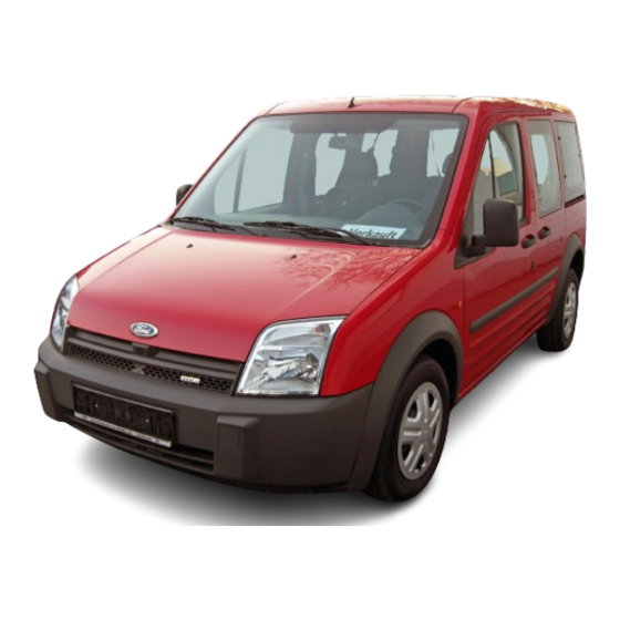
Table of Contents

Advertisement

General Information - About This Manual

Description and Operation

Introduction
This manual has been written in a format that is designed to meet the needs of technicians
worldwide. The objective is to use common formats and include similar content in each
manual.
This manual provides general descriptions for accomplishing diagnosis and testing, service
and repair work with tested, effective techniques. Following them will help assure reliability.

Special Tools

The special tool(s) table provided at the beginning of each procedure shows all special tools
required to carry out a repair. Where possible, illustrations are provided to assist in
identifying the special tool required.

Important Safety Instructions

Appropriate service methods and correct repair procedures are essential for the safe,
reliable operation of all motor vehicles as well as the personal safety of the individual
carrying out the work.
This manual cannot possibly anticipate all such variations and provide advice or cautions as
to each. Anyone who departs from the instructions provided in this manual must first
establish that he compromises neither his personal safety nor the vehicle integrity by his
choice of methods, tools or components.
Warnings, Cautions and Notes in This Manual
WARNING: Warnings are used to indicate that failure to follow a procedure correctly
may result in personal injury.
CAUTION: Cautions are used to indicate that failure to follow a procedure correctly
may result in damage to the vehicle or equipment being used.
NOTE: Notes are used to provide additional essential information required to carry out a
complete and satisfactory repair.
As you read through this manual, you will come across WARNINGS, CAUTIONS and NOTES.
A warning, caution or note is placed at the beginning of a series of steps if it applies to
multiple steps. If the warning, caution or note only applies to one step, it is placed at the
beginning of the specific step (after the step number).
How to Use This Manual
This manual covers diagnosis and testing, service and repair procedures.
This manual is structured into groups and sections, with specific system sections collected
together under their relevant group.
A group covers a specific portion of the vehicle. The manual is divided into five groups,
General Information, Chassis, Powertrain, Electrical and Body and Paint. The number of the
group is the first number of a section number.
Pages at the start of the manual list all sections available. Each section has a contents list
detailing Specifications, Description and Operation, Diagnosis and Testing, In Vehicle
Repairs, Disassembly and Assembly, Removal and Installation.
If components need to be removed or disassembled in sequence, the sequence will be
identified numerically in a graphic and the corresponding text will be numbered accordingly.
All left and right-hand references to the vehicle are taken from a position sitting in the
Transit/Tourneo Connect 2002.5 (06/2002-)
http://vnx.su
Print

Advertisement

Table of Contents
loading

Summary of Contents for Ford Transit 2002

  • Page 1 General Information - About This Manual Transit/Tourneo Connect 2002.5 (06/2002-) Print Description and Operation Introduction This manual has been written in a format that is designed to meet the needs of technicians worldwide. The objective is to use common formats and include similar content in each manual.
  • Page 2 driver seat looking forward. All left and right-hand references to the engine are taken from a position at the flywheel looking towards the front camshaft pulley. Where appropriate, instructions will be given for the use of the diagnostic tool. Overview Procedures Overview procedures contain an exploded view illustration(s).
  • Page 3 Component Tests A component test is used when a component is tested in multiple pinpoint tests, or if a procedure is too complicated to be formatted within a single page of the pinpoint test. Graphics Test graphics show the measurement or test to be performed in a test step. A representative tester graphic is used for voltmeters and ohmmeters.
  • Page 4 General Information - Health and Safety Transit/Tourneo Connect 2002.5 (06/2002-) Precautions Print Description and Operation Introduction Many of the procedures associated with vehicle maintenance and repair involve physical hazards or other risks to health. This subsection lists, alphabetically, some of these hazardous operations and the materials and equipment associated with them.
  • Page 5 Air Bags - Do's Do store modules in an upright position. Do keep modules dry. Do carry modules with the cover side pointing away from the body. Do place modules with their cover side upwards. Do carefully inspect modules for damage. Do stand to one side when connecting modules.
  • Page 6 Those based on polymer emulsions and rubber latexes may contain small amounts of volatile toxic and harmful chemicals. Skin and eye contact should be avoided and adequate ventilation provided during use. Hot Melt Adhesives In the solid state, they are safe. In the molten state they may cause burns and health hazards may arise from the inhalation of toxic fumes.
  • Page 7 these vapors. Antifreeze may be absorbed through the skin in toxic or harmful quantities. Antifreeze, if swallowed, can be fatal and MEDICAL ATTENTION SHOULD BE SOUGHT IMMEDIATELY. These products must not be used in any cooling or industrial water system that is connected or linked to general, food preparation or drinking water supplies.
  • Page 8 breathing vapors, aerosols, dusts or fumes; inadequate container labeling; fire and explosion hazards. Do wash before job breaks, before eating, smoking, drinking or using toilet facilities when handling chemical materials. Do keep work areas clean, uncluttered and free of spills. Do store chemical materials according to national and local regulations.
  • Page 9 Dusts Powder, dusts or clouds may be irritant, harmful or toxic. Avoid breathing dusts from powdery chemical materials or those arising from dry abrasion operations. Wear respiratory protection if ventilation is inadequate. Fine dusts of combustible material can present an explosion hazard. Avoid explosive limits and sources of ignition.
  • Page 10 The fibrous nature of surfaces and cut edges can cause skin irritation. This is usually a physical and not a chemical effect. Precautions should be taken to avoid excessive skin contact through careful organization of work practices and the use of gloves. Fire See also Welding, Foams, Legal Aspects.
  • Page 11 Freon See Air Conditioning Refrigerant. Fuels See also, Fire, Legal Aspects, Chemicals and Solvents. Avoid skin contact with fuel where possible. Should contact occur, wash the affected skin with soap and water. Gasoline (Petrol) Highly flammable - observe No Smoking policy. Swallowing can result in mouth and throat irritation and absorption from the stomach can result in drowsiness and unconsciousness.
  • Page 12 Inhalation in high concentrations may cause dizziness, headache, nausea and loss of co- ordination. Very high concentrations may result in loss of consciousness. Contact with liquefied petroleum gas (LPG) or compressed natural gas (CNG) to the skin may cause cold burns and frost bite. Long sleeved cotton overalls, steel toe capped safety boots and rubber neoprene gloves should be worn during removal and installation of LPG/CNG fuel system components.
  • Page 13 Transmission Fluids Safety instructions Certain Transmission and Power Steering fluids supplied to Ford may contain additives which have the potential to cause skin disease (dermatitis) to exposed persons. The dermatitis may be irritant or allergic in nature. Risks are higher where prolonged or repeated skin contact with a fluid may occur.
  • Page 14 Safety Data Sheets Safety Data Sheets, which detail specific material handling instructions and precautions are available from the respective national sales company, and via internet www.msds.ford.com. Used Engine Oil Prolonged and repeated contact with mineral oil will result in the removal of natural fats from the skin, leading to dryness, irritation and dermatitis.
  • Page 15 Paints See also Solvents, Chemical Materials. Highly flammable, flammable - observe No Smoking policy One Pack Can contain harmful or toxic pigments, driers and other components as well as solvents. Spraying should be carried out only with adequate ventilation. Two Pack Can also contain harmful and toxic unreacted resins and resin hardening agents.
  • Page 16 Aspiration into the lungs, for example through vomiting, is the most serious consequence of swallowing. Avoid splashes to the skin, eyes and clothing. Wear protective gloves, goggles and clothing if necessary. Make sure there is good ventilation when in use, avoid breathing fumes, vapors and spray mists and keep containers tightly sealed.
  • Page 17 the acid before disposing of the decomposed Viton residue and final cleaning of the area. After use, the plastic gloves should be discarded carefully and safely. Welding See also Fire, Electric Shock, Gas Cylinders. Welding processes include Resistance Welding (Spot Welding), Arc Welding and Gas Welding.
  • Page 18 warnings. 1. 1. Components or assemblies displaying the caution triangle and open book symbol advise consultation of the relevant section of the owner literature before touching or attempting adjustments of any kind. 2. 2. Components or assemblies displaying the warning triangle with the `electrified' arrow and open book symbol give warning of inherent high voltages.
  • Page 19 4. 4. Components or assemblies displaying this symbol give warning that the component contains a corrosive substance. See Acids and Alkalis in this subsection. 5. 5. Displaying the caution circle with a deleted lighted match symbol, caution against the use of naked lights or flames within the immediate vicinity due to the presence of highly flammable or explosive liquids or vapors.
  • Page 20 General Information - Standard Workshop Transit/Tourneo Connect 2002.5 (06/2002-) Practices Print Description and Operation Vehicle in Workshop When working on a vehicle in the workshop always make sure that: the parking brake is applied or the wheels are securely chocked to prevent the vehicle moving forwards or backwards.
  • Page 21 connected. While it is not recommended that the vehicle is jump started, it is recognized that this may occasionally be the only practical way to mobilize a vehicle. In such an instance, the discharged battery must be recharged immediately after jump starting to avoid permanent damage.
  • Page 22 Dry cleaning. Removal of loose dirt with soft or cable brushes. Scraping dirt off with a piece of metal or wood. Wiping off with a rag. WARNING: Wear eye protection when cleaning vehicle components with compressed air, a steam cleaner or a power washer. Failure to follow this instruction may result in personal injury.
  • Page 23 General Information - Solvents, Sealants Transit/Tourneo Connect 2002.5 (06/2002-) and Adhesives Print Description and Operation Introduction WARNING: Always handle all solvents, sealers and adhesives with extreme care. Some contain chemicals or give off fumes which can be dangerous to health. Always follow the manufacturers instructions.
  • Page 24 General Information - Road/Roller Transit/Tourneo Connect 2002.5 (06/2002-) Testing Print Description and Operation Road or roller testing may be carried out for various reasons and a procedure detailing pre- test checks, engine starting and stopping, pre-driving checks, on-test checks and final checks to be completed on completion of the test is given below.
  • Page 25 During the road or roller test, check: that the clutch pedal operation is not stiff or heavy. that the initial gear engagement is smooth and there is no evidence of clutch drag. that the parking brake control operates smoothly and releases quickly and completely. that the clutch takes up the drive smoothly, without slip or judder.
  • Page 26 General Information - Diesel Fuel System Transit/Tourneo Connect 2002.5 (06/2002-) Health and Safety Precautions Print Description and Operation WARNINGS: Fuel may not give adequate warning before toxic or harmful effects arise. Exposure to fuel can be harmful and can cause severe health damage or death. Provide adequate ventilation when working on fuel systems.
  • Page 27 Make sure to use a steel topped workbench covered with clean, lint-free, non-flocking material. Make sure that all parts removed from the vehicle are placed on the lint-free, non- flocking material. Make sure that any protective clothing worn is clean and made from lint-free, non- flocking material.
  • Page 28 General Information - Battery and Battery Transit/Tourneo Connect 2002.5 (06/2002-) Charging Health and Safety Precautions Print Description and Operation WARNINGS: Batteries contain sulphuric acid, avoid contact with skin, eyes or clothing. Wear safety goggles when working near the battery to protect against possible splashing of the acid solution.
  • Page 29 General Information - Supplemental Restraint System (SRS) Health and Safety Transit/Tourneo Connect 2002.5 (06/2002-) Precautions Print Description and Operation WARNINGS: Only qualified technicians are allowed to work on pyrotechnic components. INHALED: Exposure to pyrotechnic residue may cause low blood pressure, severe headache, irritation of mucous membranes, fainting, shortness of breath or rapid pulse.
  • Page 30 Pyrotechnic components must not be disassembled. Pyrotechnic components are not interchangeable between vehicles. Always carry a live air bag module away from the body with the air bag or trim cover pointing upwards. Live air bag modules must be placed in a suitable cage when removed from the vehicle.
  • Page 31 Identification Codes - Identification Codes Transit/Tourneo Connect 2002.5 (06/2002-) Print Description and Operation Identification Codes NOTE: The beginning and end of the Vehicle Identification Number are each shown by an asterisk (*). The Vehicle Identification Number (VIN) number for identifying the vehicle is stamped into the body on the right-hand sill.
  • Page 32 VIN Position 1, 2 and 3 - World Manufacturer Identifier Code World Manufacturer Ford-Werke AG Germany (European vehicles) Ford Otomotiv Sanayi A. S., Turkey (for the Turkish market). VIN Position 4 and 10 - Body Type Code Body Type 5 seat van (N1)
  • Page 33 Code Model Transit/Tourneo Connect VIN Position 11 - Year of Manufacture Code Year of Manufacture 2002 2003 2004 2005 2006 2007 2008 2009 VIN Position 12 - Month of Manufacture Build month 2002 2003 2004 2005 2006 2007 2008 2009 January February March...
  • Page 34 Gross vehicle mass (GVM) Gross train mass (GTM) Maximum permissible front axle mass Maximum permissible rear axle mass Model type codes Wheelbase codes Final drive ratio codes Special vehicles only Transaxle codes Door combination codes Suspension codes Hand of drive codes Body color codes Brake codes Interior trim codes...
  • Page 35 4.06 4.06 3.80 Item 10: Special vehicles only Code Description Only used for special vehicles Field 11: Transaxle codes Code Transaxle MTX-75 (diesel) MTX-75 (petrol) Item 12: Door combination codes Code Door combination 4-door 5-door, sliding door on RHS 5-door, sliding door on LHS 6-door 3-door 4-door (with tailgate)
  • Page 36 Tonic Sublime or Blue Ambition Caramella, Frozen White, Plum Blush, Marmalade or Willow Item 16: Brakes codes Code Brake With anti-lock brakes (ABS) with Traction Control or Electronic Stability Program With ABS without Traction Control or Electronic Stability Program With ABS with Traction Control or Electronic Stability Program Item 17: Interior trim codes Code Interior Trim...
  • Page 37 T200 2025 2825 T200 2025 2825 T220 2230 3030 T200 2035 2835 T200 2035 2835 T220 2240 3040 T210 2080 2880 T220 2260 3060 T230 2260 3060 T230 2340 3140 T230 2340 3140 K200 2045 2845 K210 2110 2910 K220 2175 2975 K230...
  • Page 38 Jacking and Lifting - Jacking Transit/Tourneo Connect 2002.5 (06/2002-) Print Description and Operation WARNING: Only the specified jacking points may be used for jacking up and supporting the vehicle. CAUTION: Park the vehicle on a flat, level and stable surface. If the vehicle must be lifted on a soft surface, the supporting forces must be spread by using a suitable base under the jack.
  • Page 39 Jacking and Lifting - Lifting Transit/Tourneo Connect 2002.5 (06/2002-) Print Description and Operation WARNING: Only raise the vehicle at the specified lifting points. CAUTION: Place blocks underneath the hoist points if a two-column ramp is used. http://vnx.su...
  • Page 40 Noise, Vibration and Harshness - Noise, Transit/Tourneo Connect 2002.5 (06/2002-) Vibration and Harshness (NVH) Print Description and Operation Noise, vibration and harshness (NVH) is becoming more important as vehicles become more sophisticated and passenger comfort levels increase. This section is designed to aid in the diagnosis and testing and repair of NVH concerns.
  • Page 41 Do Not Cure the Symptom and Leave the Cause Lowering the pressure in a front tire may correct the condition of a vehicle leaning to one side, but it does not correct the original condition. Be Positive the Cause is Found Double check findings.
  • Page 42 Noise, Vibration and Harshness - Noise, Transit/Tourneo Connect 2002.5 (06/2002-) Vibration and Harshness (NVH) Print Diagnosis and Testing Inspection and Verification 1. 1. Verify the customer concern. 2. 2. Visually inspect for obvious signs of mechanical or electrical damage. 3. 3. If an obvious cause for an observed or reported concern is found, correct the cause (if possible) before proceeding to the next step.
  • Page 43 Therefore, make sure that none of the following conditions are the cause of the noise before proceeding with a driveline teardown and diagnosis. In certain conditions, the pitch of the exhaust may sound very much like gear noise. At other times, it can be mistaken for a wheel bearing rumble. Tires, especially snow tires, can have a high pitched tread whine or roar, similar to gear noise.
  • Page 44 smallest bit of information, because it may turn out to be the most important. 2. 2. Do not touch anything until a road test and a thorough visual inspection of the vehicle have been carried out. Leave the tire pressures and vehicle load just where they were when the condition was first observed.
  • Page 45 damaged powertrain/drivetrain mounts. Road Conditions An experienced technician will always establish a route that will be used for all NVH diagnosis road tests. The road selected should be reasonably smooth, level and free of undulations (unless a particular condition needs to be identified). A smooth asphalt road that allows driving over a range of speeds is best.
  • Page 46 knocking deceleration Washer bottle Deceleration, acceleration and single impact Loose suspension bolts All driving conditions Instrument panel rattle/squeak All driving conditions. Engine rpm dependant X X X X X = Noise will most likely occur in this operating condition. O = Noise can possibly occur in this operating condition. Blank = Noise is unlikely to occur in this operating condition.
  • Page 47 Before conducting a vehicle test to identify a NVH concern carry out the following checks. 1. 1. Check the tire pressures and adjust to specification, as necessary. 2. 2. Make sure the steering system fluid is correct, the system is free of leaks and is operating correctly.
  • Page 48 steering pump. Certain amount of noise level pump. acceptable, not a safety critical item. Power Steering Whine Noise Test Condition Listen for steering whine noise with the vehicle parked, transmission in neutral and all windows closed in the following test conditions. 1.
  • Page 49 Listen for steering hiss noise with the vehicle parked, transmission in neutral and all windows closed in the following test conditions. Possible Symptom Sources Action NOTE: Engine speed at idle turning the steering wheel CHECK the slowly lock to lock. installation and Floor seal.
  • Page 50 Power Steering Mechanical Knock Noise (PAS on) Test Condition Listen for steering knock noise with the engine speed at idle in the following test conditions (power assist). 1. 1. Turn the steering wheel to a steering lock and return to center quickly. 2.
  • Page 51 flow rate (by safety critical design). item. Power Steering Column Knock Noise Test Condition Listen for steering knock noise in the following test conditions with windows closed. 1. 1. Drive over cobbled stones at low speed 16-40 km/h (10-25 mph) with and without steering input carefully listening for knock sounds.
  • Page 52 Symptom Possible Sources Action Certain amount of noise level Steering wheel to acceptable, not a safety critical shroud interference. item. Certain amount of noise level Steering column acceptable, not a safety critical bearing. item. CHECK if floor covering is Power steering system grinding noise – Foreign material in obstructing the steering gear an abrasive noise (like sand paper...
  • Page 53 necessary to correct the condition. Then check the operation of the system to make sure the condition has been corrected. After verifying that the condition has been corrected, make sure all components removed have been installed. PINPOINT TEST A : SHAKE AND VIBRATION WHILE DRIVING TEST DETAILS/RESULTS/ACTIONS CONDITIONS...
  • Page 54 GO to B4: CHECK THE POWERTRAIN/DRIVETRAIN MOUNTS Carry out the powertrain/drivetrain mount neutralizing procedure Are the powertrain/drivetrain mounts OK? Vehicle condition corrected. ROAD TEST as necessary. INSTALL new powertrain/drivetrain mounts as necessary. ROAD TEST as necessary. PINPOINT TEST C : IDLE BOOM/SHAKE/VIBRATION/SHUDDER TEST DETAILS/RESULTS/ACTIONS CONDITIONS...
  • Page 55 GO to INSTALL new wheels or tires as necessary. REFER to: Wheel and Tire (204-04 Wheels and Tires, Removal and Installation). ROAD TEST as necessary. D2: INSPECT THE WHEEL BEARINGS Inspect the wheel bearings. REFER to: Wheel Bearing Inspection (204-00 Suspension System - General Information, General Procedures).
  • Page 56 Check any non-factory installed accessories for being the source of the noise. For example: touch condition body-to-frame, antennas, deflectors and fog lights. Are the accessories the cause of the noise? ADJUST, REPAIR, or INSTALL new accessories or fasteners as required. ROAD TEST as necessary.
  • Page 57 Noise, Vibration and Harshness - Transit/Tourneo Connect 2002.5 (06/2002-) Powertrain/Drivetrain Mount Neutralizing Print General Procedures NOTE: There is no procedure for neutralizing the powertrain/drivetrain mounts. To check the alignment of the powertrain mounts visually, proceed as follows. 1. Loosen the rear support insulator retaining bolts (if equipped).
  • Page 58 Suspension System - General Information Transit/Tourneo Connect 2002.5 (06/2002-) - Specifications Print Front Wheel Alignment (at curb weight) — Caster Model Decimal Degrees Degrees and Minutes Nominal Tolerance Range Nominal Tolerance Range All variants +1.80° +2.30° to +1.30° +1°48' +2°18' to +1°18' Maximum variance left-hand side to right-hand side Caster 1.00°...
  • Page 59 Torque Specifications Description lb-ft lb-in Tie-rod end locknut http://vnx.su...
  • Page 60 Front Suspension - Front Suspension Transit/Tourneo Connect 2002.5 (06/2002-) Print Description and Operation A newly developed Mc-Pherson front suspension with L-shaped lower arms is used. These lower suspension arms are linked via two horizontal rubber mountings to a reinforced and extremely rigid front axle crossmember.
  • Page 61 Item Part Number Description Suspension strut top mount Spring Spindle carrier Ball head Heat shield Wheel bearing Studs Wheel hub NOTE: During installation of the front wheel bearing it is important to adhere to the specified installation position, as the Anti-lock Brake System (ABS) sensor ring is located in the wheel bearing.
  • Page 62 Front Suspension - Front Suspension Transit/Tourneo Connect 2002.5 (06/2002-) Print Diagnosis and Testing REFER to Section 204-00 Suspension System - General Information. http://vnx.su...
  • Page 63 Front Suspension - Front Wheel Bearing Transit/Tourneo Connect 2002.5 (06/2002-) Print Removal and Installation Special Tool(s) Adaptor for 204-158 (Thrust Pad) 204-158-01 (14-038-01) Installer, Front Wheel Bearing 204-160 (14-040) Adapter for 205-074 205-074-01 (15-064) Installer, Rear Hub Oil Seal 205-075 (15-036) Remover, Bearing/Gear 204-348 Installer/Aligner, Crankshaft Rear Oil Seal...
  • Page 64 4. Using the special tools, remove and discard the wheel bearing. Installation CAUTIONS: Avoid any impact on the wheel speed sensor ring. Make sure the wheel speed sensor ring is clean. Avoid any contact between the wheel speed sensor ring and a magnetic surface. CAUTION: Make sure the wheel bearing is installed into the wheel knuckle with the wheel speed sensor ring, colored black,...
  • Page 65 4. Install the wheel knuckle. For additional information, refer to: Wheel Knuckle (204-01 Front Suspension, Removal and Installation). http://vnx.su...
  • Page 66 Front Suspension - Lower Arm Transit/Tourneo Connect 2002.5 (06/2002-) Print Removal and Installation General Equipment Two leg puller Removal 1. Remove the wheel and tire. For additional information, refer to Section 204-04 Wheels and Tires. NOTE: Use a T50 Torx driver to prevent the ball joint from rotating.
  • Page 67 bearing washer. NOTE: Do not fully tighten the lower arm retaining bolts at this stage. Install the lower arm. 3. Tighten the lower arm retaining bolts in the sequence shown. 1. The front retaining bolt. 2. The rear clamp upper retaining bolt. 3.
  • Page 68 Front Suspension - Front Stabilizer Bar Transit/Tourneo Connect 2002.5 (06/2002-) Print Removal and Installation Special Tool(s) Alignment Pins, Subframe 205-316 (15-097A) Separator, Ball Joint 211-020 (13-006) General Equipment Two leg puller Transmission jack Securing strap Removal NOTE: Make sure the road wheels are in the straight ahead position.
  • Page 69 CAUTION: Protect the ball joint seal using a soft cloth to prevent damage. Using the special tool, detach the tie-rod end from the wheel knuckle on both sides. 1. Release the tie-rod end. 2. Remove and discard the tie rod end retaining nut.
  • Page 70 wooden block, support the crossmember. 11. Using a suitable securing strap, secure the crossmember to the transmission jack. 12. Remove the crossmember retaining bolts (transmission jack removed for clarity). 13. Lower the crossmember approximately 100 mm. 14. Remove and discard the crossmember ball bearing washers.
  • Page 71 stabilizer bar with no lubricant. Install the stabilizer bar bushings. 3. Position the stabilizer bar on the crossmember. NOTE: Do not fully tighten the stabilizer bar clamp retaining bolts at this stage. Install the stabilizer bar clamp on both sides. WARNING: When installing the stabilizer bar, the measurement must be taken in a vertical plane between the crossmember and...
  • Page 72 holes. CAUTION: While tightening the crossmember retaining bolts, make sure the crossmember does not move. Install the crossmember retaining bolts (transmission jack removed for clarity). 10. Remove the securing strap and the transmission jack. 11. Install the engine support insulator center bolt. NOTE: Use a 5 mm Allen key to prevent the ball joint from rotating.
  • Page 73 information, refer to Section 204-04 Wheels and Tires. WARNING: Install a new steering column shaft retaining bolt to the steering gear pinion extension. Failure to follow this instruction may result in personal injury. NOTE: Make sure the road wheels are in the straight ahead position.
  • Page 74 Front Suspension - Wheel Knuckle Transit/Tourneo Connect 2002.5 (06/2002-) Print Removal and Installation Special Tool(s) Lever, Wheel Knuckle 204-052 (14-026 A) Installer, Halfshaft 204-161 (14-041) Separator, Ball Joint 211-020 (13-006) General Equipment Two leg puller Three leg puller Removal All vehicles 1.
  • Page 75 5. Remove the brake disc. Remove and discard the retaining washer (if equipped). Vehicles with anti-lock brakes 6. Detach the wheel speed sensor from the wheel knuckle. All vehicles CAUTION: Leave the tie-rod end retaining nut in place to protect the ball joint stud.
  • Page 76 NOTE: Use a T50 Torx driver to prevent the ball joint from rotating. Loosen the lower arm ball joint retaining nut. CAUTIONS: Leave the lower arm ball joint retaining nut in place to protect the ball joint stud. Protect the ball joint seal using a soft cloth to prevent damage.
  • Page 77 knuckle. Installation All vehicles 1. Check the lower arm ball joint heat shield for damage. Install a new heat shield if necessary. For additional information, refer to Lower Arm Ball Joint in this section. 2. Install the wheel knuckle. CAUTION: Make sure the halfshaft is completely installed into the wheel hub.
  • Page 78 Vehicles with anti-lock brakes 6. Attach the wheel speed sensor to the wheel knuckle. All vehicles 7. Install the brake disc. 8. Attach the brake caliper and anchor plate to the wheel knuckle. WARNING: Install a new wheel hub retaining nut. Failure to follow this instruction may result in personal injury.
  • Page 79 12. Tighten the strut and spring assembly top mount retaining nuts. http://vnx.su...
  • Page 80 Front Suspension - Front Strut and Spring Transit/Tourneo Connect 2002.5 (06/2002-) Assembly Print Removal and Installation Special Tool(s) Lever, Wheel Knuckle 204-052 (14-026 A) Removal 1. Remove the wheel and tire. For additional information, refer to Section 204-04 Wheels and Tires.
  • Page 81 Installation CAUTION: With the aid of another technician, support the strut and spring assembly. Install the strut and spring assembly. 2. Attach the suspension strut to the wheel knuckle. NOTE: Use a 5 mm Allen key to prevent the ball joint from rotating. Attach the stabilizer bar connecting link to the suspension strut.
  • Page 82 Front Suspension - Lower Arm Ball Joint Transit/Tourneo Connect 2002.5 (06/2002-) Print Removal and Installation Special Tool(s) Remover/Installer, Ball Joint 204-288A (14-063A) Adapter for 204-288A 204-288A-01 General Equipment Two leg puller Removal 1. Remove the wheel knuckle. For additional information, refer to: Wheel Knuckle (204-01 Front Suspension, Removal and...
  • Page 83 2. Using the special tool and a suitable two leg puller, install the lower arm ball joint. 3. Install the circlip. 4. Remove the wheel knuckle from the vise. 5. Install the wheel knuckle. For additional information, refer to: Wheel Knuckle (204-01 Front Suspension, Removal and Installation).
  • Page 84 Front Suspension - Front Strut and Spring Transit/Tourneo Connect 2002.5 (06/2002-) Assembly Print Disassembly and Assembly Special Tool(s) Compressor, Coil Spring 204-167 (14-042) Adapter for 204-167 204-167-01 (14-042-01) Disassembly WARNING: The spring is under extreme tension; care must be taken at all times. Failure to follow this instruction may result in personal injury.
  • Page 85 Assembly CAUTION: The ends of the spring must locate correctly against the spring seats. To assemble, reverse the disassembly procedure. http://vnx.su...
  • Page 86 Rear Suspension - Specifications Transit/Tourneo Connect 2002.5 (06/2002-) Print Torque Specifications Description Nm lb-ft lb-in Shock absorber lower mounting retaining bolt Shock absorber upper mounting retaining nuts Spring U-bolt retaining nuts Spring rear mounting retaining bolts Wheel spindle retaining bolts Wheel hub retaining nut Brake hose to brake caliper union Wheel speed sensor retaining bolt...
  • Page 87 Rear Suspension - Rear Suspension Transit/Tourneo Connect 2002.5 (06/2002-) Print Description and Operation Rear axle The rear axle consists of a steel tube which acts as the axle body and at the end of which the mountings for the wheel suspensions are welded. Good lateral guidance is achieved by this construction.
  • Page 88 The mounting points and the characteristics differ, depending on the wheel base. Furthermore, leaf springs with different ratings are installed, depending on the vehicle construction and wheel base. These may be either single or double leaf springs. All vehicle variants are equipped with a stabiliser. This is connected to the vehicle body by link rods, one on the left and one on the right.
  • Page 89 Rear Suspension - Rear Suspension Transit/Tourneo Connect 2002.5 (06/2002-) Print Diagnosis and Testing REFER to Section 204-00 Suspension System - General Information. http://vnx.su...
  • Page 90 Rear Suspension - Wheel Spindle Transit/Tourneo Connect 2002.5 (06/2002-) Print Removal and Installation Removal Vehicles with rear drum brakes 1. Remove the brake drum. For additional information, refer to Section 206-02 Drum Brake. Vehicles with rear disc brakes 2. Remove the brake disc. For additional information, refer to Section 206-04 Rear Disc Brake.
  • Page 91 Rear Suspension - Rear Stabilizer Bar Transit/Tourneo Connect 2002.5 (06/2002-) Print Removal and Installation Removal NOTE: Note the position of each component before removal. 1. Raise and support the vehicle. For additional information, refer to: Jacking (100-02 Jacking and Lifting, Description and Operation) / Lifting (100-02 Jacking and Lifting, Description...
  • Page 92 2. Install the stabilizer bar. 3. Install the stabilizer bar clamp on both sides. NOTE: Install new stabilizer bar connecting link to stabilizer bar retaining nuts. NOTE: Use a 6 mm Allen key to prevent the ball joint from rotating. Attach the stabilizer bar connecting link to the stabilizer bar on both sides.
  • Page 93 Rear Suspension - Spring Transit/Tourneo Connect 2002.5 (06/2002-) Print Removal and Installation General Equipment Transmission jack Removal 1. Raise and support the vehicle. For additional information, refer to Section 100- 02 Jacking and Lifting. 2. Using a suitable transmission jack, support the beam axle.
  • Page 94 hose, make sure the beam axle is only lowered sufficiently to allow removal of the spring. Using a suitable transmission jack, lower the beam axle. 8. Remove the spring. Installation NOTE: Final tightening of the rear suspension components should be carried out when the vehicle weight is on the road wheels.
  • Page 95 5. Lower and remove the transmission jack. 6. Lower the vehicle. 7. Tighten the spring front locknut. 8. Tighten the spring rear locknut. 9. Tighten the spring U-bolt retaining nuts. http://vnx.su...
  • Page 96 Rear Suspension - Beam Axle Transit/Tourneo Connect 2002.5 (06/2002-) Print Removal and Installation General Equipment Transmission jack Removal All vehicles 1. Remove the brake backing plates. For additional information, refer to Section 206-02 Drum Brake. WARNING: Make sure the beam axle is secured to the transmission jack.
  • Page 97 7. Remove the guide plate. 8. Remove the beam axle. 9. Remove the beam axle spacer (if equipped). Installation NOTE: Final tightening of the beam axle components should be carried out when the vehicle weight is on the road wheels. All vehicles 1.
  • Page 98 ball joint from rotating. Attach the stabilizer bar connecting link to the beam axle on both sides. Vehicles without anti-lock brakes 6. Attach the brake load sensor proportioning valve to the beam axle. All vehicles NOTE: Do not fully tighten the shock absorber retaining nuts at this stage.
  • Page 99 13. Tighten the shock absorber lower mounting retaining nuts. Vehicles without anti-lock brakes 14. Adjust the brake load sensor proportioning valve. For additional information, refer to Section 206- 00 Brake System - General Information. http://vnx.su...
  • Page 100 Rear Suspension - Wheel Hub Transit/Tourneo Connect 2002.5 (06/2002-) Print Removal and Installation Removal Vehicles with rear drum brakes 1. Remove the brake drum. For additional information, refer to Section 206-02 Drum Brake. Vehicles with rear disc brakes 2. Remove the brake disc. For additional information, refer to Section 206-04 Rear Disc Brake.
  • Page 101 Rear Suspension - Rear Stabilizer Bar Link Transit/Tourneo Connect 2002.5 (06/2002-) Print Removal and Installation Removal NOTE: Removal steps in this procedure may contain installation details. 1. Raise and support the vehicle. Refer to: Jacking (100-02 Jacking and Lifting, Description and Operation). Refer to: Lifting (100-02 Jacking and Lifting,...
  • Page 102 Wheels and Tires - Specifications Transit/Tourneo Connect 2002.5 (06/2002-) Print Torque Specifications Description lb-ft lb-in Wheel nuts - Alloy wheel Wheel nuts - Steel wheel http://vnx.su...
  • Page 103 Wheels and Tires - Wheels and Tires Transit/Tourneo Connect 2002.5 (06/2002-) Print Description and Operation General A considerable amount of information is shown on the side wall of a tyre, and part of it can be very important for the installation or maintenance of the tyre. Item Part Number Description...
  • Page 104 Tyre type (radial) Tubeless tyre Approval character and number according to EEC (Economic Commission for Europe) Manufacturer code (according to DOT) Country of manufacture Product name of tyre Maximum load (according to DOT in lbs) Maximum pressure (according to DOT in psi) Marking for TWI (Tread Wear Indicator) Details on the construction of the tyre (according to DOT) M&S (Slush and Snow = winter tyres) (optional)
  • Page 105 Item Part Number Description Profile width Rim flange Rim width Width overall Rim diameter Side wall External diameter Maximum speed rating If an emergency tyre is used, whose size differs from the tyres usually mounted on the vehicle, a marking showing the maximum speed of 80 km/h (50 mph) must be present on the tyre.
  • Page 106 Wheels and Tires - Wheels and Tires Transit/Tourneo Connect 2002.5 (06/2002-) Print Description and Operation Wheels and Tyres 195/65 R 15 tyres are standard equipment. Depending on payload, tyres with the load rating of 91T or 95T are used. The wheel size is 6Jx15, the hole pitch circle 107.95 mm. These are also available as light alloy wheels.
  • Page 107 Wheels and Tires - Wheels and Tires Transit/Tourneo Connect 2002.5 (06/2002-) Print Diagnosis and Testing Inspection and Verification Visual Inspection Chart Mechanical Wheel(s) Tire(s) Tire pressure(s) * Wheel nuts Wheel studs * Vehicles equipped with a tire pressure monitoring system must be inspected for correct operation using the diagnostic tool.
  • Page 108 Vehicle Speed Sensitive This means that the vibration always occurs at the same vehicle speed and is not affected by engine torque, engine speed or the transmission gear selected. Engine Speed Sensitive This means that the vibration occurs at varying vehicle speeds when a different transmission gear is selected.
  • Page 109 necessary. REFER to: (204-04 Wheels and Tires) Specifications (Specifications), Wheel and Tire (Removal and Installation). Wobble or Damaged wheel. INSPECT the wheel rims for damage. BALANCE the shimmy wheel and tire assemblies. Using a suitable dial affecting wheel indicator gauge and holding fixture, CHECK lateral and runout radial runout of the wheel and tire assemblies.
  • Page 110 Wheel and Tire (Removal and Installation). Seized wheel Corrosion. CAUTION: Do not permit lubricant to get on cone sets nuts of stud holes or on cone angle of wheel nuts. If corrosion is slight, wire brush away. If corrosion is excessive, INSTALL new wheel studs and nuts.
  • Page 111 Wheels and Tires - Wheel and Tire Transit/Tourneo Connect 2002.5 (06/2002-) Print Removal and Installation Removal CAUTIONS: Do not use heat to loosen a seized wheel nut. Heat may damage the wheel and wheel hub. Do not use power tools on locking wheel nuts. 1.
  • Page 112 Front Drive Halfshafts - Specifications Transit/Tourneo Connect 2002.5 (06/2002-) Print Torque Specifications Item lb-ft lb-in Intermediate shaft center bearing Wheel hub retaining nut Strut and spring assembly top mount nuts Constant velocity (CV) joint boot retaining clamps Tie-rod end retaining nut Lower arm ball joint retaining nut http://vnx.su...
  • Page 113 Front Drive Halfshafts - Front Drive Transit/Tourneo Connect 2002.5 (06/2002-) Halfshafts Print Diagnosis and Testing Inspection and Verification NOTE: New front wheel drive halfshafts should not be installed unless disassembly and inspection reveals unusual wear. 1. 1. Inspect front wheel driveshaft joint boots for evidence of cracks, tears or splits. NOTE: While inspecting the front wheel driveshaft CV joint boots, watch for indentations (dimples) in the boot convolutions.
  • Page 114 in front wheel hub. Assembly in this section. Shudder Vibration Excessively high CV joint CHECK ride height, VERIFY correct During operating angles caused by spring rate and CHECK items under Acceleration. incorrect ride height. Halfshaft Joint Pullout. REPAIR or INSTALL new as necessary. Excessively worn or damaged INSPECT and INSTALL new as inboard front wheel driveshaft...
  • Page 115 Front Drive Halfshafts - Front Halfshaft LH Transit/Tourneo Connect 2002.5 (06/2002-) Print Removal and Installation Special Tool(s) Installer, Halfshaft 204-161 (14-041) Remover, Halfshaft 204-226 (16-092) Adapter for 204-226 204-226-01 (16-092-01) Slide Hammer 205-047 (15-011) Separator, Ball Joint 211-020 (13-006) General Equipment Three leg puller Two leg puller Materials...
  • Page 116 3. Remove the front wheel and tire. For additional information, refer to Section 204-04 Wheels and Tires. CAUTION: Leave the tie-rod end retaining nut in place to protect the ball joint stud. NOTE: Use a 5 mm Allen key to prevent the ball joint from rotating.
  • Page 117 CAUTION: Support the halfshaft. The inner joint must not be bent more than 18 degrees. The outer joint must not be bent more than 45 degrees. Using a suitable three leg puller, detach the halfshaft from the wheel hub. CAUTIONS: Support the halfshaft.
  • Page 118 a soft cloth to prevent damage. NOTE: Use a T50 Torx driver to prevent the ball joint from rotating. Attach the lower arm to the wheel knuckle. NOTE: Install a new tie-rod end retaining nut. NOTE: Use a 5 mm Allen key to prevent the ball joint from rotating.
  • Page 119 Front Drive Halfshafts - Front Halfshaft Transit/Tourneo Connect 2002.5 (06/2002-) Print Removal and Installation Special Tool(s) Installer, Halfshaft 204-161 (14-041) Separator, Ball Joint 211-020 (13-006) General Equipment Three leg puller Two leg puller Removal 1. Loosen the strut and spring assembly top mount nuts by five turns.
  • Page 120 using a soft cloth to prevent damage. Using the special tool, detach the tie-rod end from the wheel knuckle (left-hand side shown). 1. Release the tie-rod end. 2. Remove the tie-rod end retaining nut. Discard the nut. NOTE: Use a T50 Torx driver to prevent the ball joint from rotating.
  • Page 121 Installation CAUTION: Make sure that the amount of grease in the CV joint does not exceed 100 grams. Fill the CV joint with grease. CAUTION: Secure the halfshaft to prevent damage to the CV joints. The inner CV joint must not be bent more than 18 degrees.
  • Page 122 ball joint from rotating. Attach the tie-rod end to the wheel knuckle. WARNING: Install a new wheel hub retaining nut. Failure to follow this instruction may result in personal injury. With the aid of another technician, apply the brakes and preload the wheel bearing by installing the new wheel hub retaining nut.
  • Page 123 Front Drive Halfshafts - Intermediate Transit/Tourneo Connect 2002.5 (06/2002-) Shaft Print Removal and Installation Special Tool(s) Separator, Ball Joint 211-020 (13-006) General Equipment Grip Wrench (Hazet 1847-1) Materials Name Specification Grease – inner joint XS4C-M1C230-A Removal 1. Loosen the strut top mount retaining nuts by four turns.
  • Page 124 CAUTIONS: Do not unscrew the lower arm ball joint retaining nut in order to protect the thread. Protect the ball joint gaiter using a soft cloth to prevent damage. Protect the heat shield using a soft cloth to prevent damage. Using a suitable two-legged puller, detach the...
  • Page 125 Close off the transmission openings to prevent fluid loss or dirt ingress. Remove the intermediate shaft. Collect the fluid in a suitable container. Remove and discard the center bearing cap and locknuts. Pull the intermediate shaft out of the transmission. Installation CAUTION: Ensure that the halfshaft oil seal is not damaged.
  • Page 126 CAUTION: Protect the heat shield using a soft cloth to prevent damage. NOTE: Do not tighten the lower suspension arm ball joint retaining nut for the moment. Attach the lower suspension arm to the spindle carrier. 6. Tighten the lower suspension arm ball joint retaining nut.
  • Page 127 Front Drive Halfshafts - Inner Constant Transit/Tourneo Connect 2002.5 (06/2002-) Velocity (CV) Joint Boot Print Removal and Installation Special Tool(s) Boot clamp tightening tool 204-169 (14-044) Separating tool, bearing/gear wheel 205-310 (15-091) Puller, bearing/gear wheel 205-311 (15-092) Installer, bushing and oil seal, transmission extension 308-046 (16-016) General Equipment Grip wrench (Hazet 1847-1)
  • Page 128 4. Remove the snap-ring. 5. Detach the tripod using the special tool. Take off the boot and discard it. Installation 1. Insert a new boot. NOTE: Renew the boot clamp. Install a new inner boot clamp using the special tool. NOTE: Chamfer points towards front drive halfshaft.
  • Page 129 Drive the tripod home onto the front drive halfshaft. NOTE: Use a new snap-ring. Install the tripod snap-ring. CAUTION: The constant velocity joint must not be packed with more than 120 g of grease. Pack the constant velocity joint with grease 6.
  • Page 130 Front Drive Halfshafts - Outer Constant Transit/Tourneo Connect 2002.5 (06/2002-) Velocity (CV) Joint Boot Print Removal and Installation Special Tool(s) Clamping Tool, Boot Retaining Clamp 204-169 (14-044) General Equipment Expanding pliers, snap-ring Materials Name Specification Constant velocity joint ESP-M1C207-A high-temperature grease Removal 1.
  • Page 131 NOTE: Install a new clamping strap. Insert the outer clamping strap into the ring groove of the rubber boot and tighten with the special tool. 4. Install the inner CV joint boot. For additional information, refer to: Inner Constant Velocity (CV) Joint Boot (205-04 Front Drive Halfshafts, Removal and Installation).
  • Page 132 Front Drive Halfshafts - Halfshaft Bearing Transit/Tourneo Connect 2002.5 (06/2002-) Print Removal and Installation Special Tool(s) 204-169 Clamping Tool, Boot Retaining Clamp 205-080 Installer, Differential Bearing 205-310 Remover, Bearing/Gear 303-255 Installer, Timing Cover Seal Materials Name Specification Grease FD-R WSS-M1C259-A1 / 3M5J-M1C259-AA General Equipment Flat-bladed screwdriver Hydraulic press...
  • Page 133 3. Special Tool(s): 205-310 General Equipment: Hydraulic press Installation 1. Special Tool(s): 205-080, 303-255 General Equipment: Hydraulic press 2. Material: Grease FD-R (WSS-M1C259-A1 / 3M5J-M1C259-AA) http://vnx.su...
  • Page 134 1. Release any trapped air. Flat-bladed General Equipment: screwdriver 4. General Equipment: Flat-bladed screwdriver 4. Special Tool(s): 204-169 http://vnx.su...
  • Page 135 Brake System - General Information - Transit/Tourneo Connect 2002.5 (06/2002-) Brake System Print Description and Operation Brake system, general information Item Part Number Description Brake system without Anti-lock Brake System (ABS) Brake system with ABS Tandem brake master cylinder Reservoir Brake servo Wheel speed sensors Internally ventilated front brake discs...
  • Page 136 Diagnosis and Testing General Equipment Pressure/vacuum gauge set The Ford approved diagnostic tool The brake system operates by transferring effort applied to the brake pedal by the driver to the brakes at each wheel. The braking effort is distributed to each wheel, using a hydraulic system. The system is assisted using a vacuum brake booster that reduces pedal effort and increases hydraulic pressure.
  • Page 137 symptoms. Certain components will be identified as possible sources while others will be eliminated by the evidence. More importantly, the customer description can reveal unsafe conditions which should be checked or corrected before a road test. The description will also help form the basic approach to the road test by narrowing the concern to specific components, vehicle speed or conditions.
  • Page 138 Installation) / Brake Caliper (206-03 Front Disc Brake, Removal and Installation). Brake warning Low brake fluid level. FILL the reservoir. CHECK the brake indicator is and clutch system for leaks including always on brake fluid in the brake booster. Leak in the hydraulic system. REPAIR the leak.
  • Page 139 bolts as necessary. Worn or damaged brake drums or INSTALL new brake drums or brake brake discs. discs. REFER to: Brake Pads (206-04 Rear Disc Brake, Removal and Installation) / Brake Shoes (206-02 Drum Brake, Removal and Installation). Pedal goes Low brake fluid level.
  • Page 140 Removal and Installation). GO to Pinpoint Test Air in the system. CHECK for leaks. BLEED the brake system. REFER to: Brake System Bleeding (206-00 Brake System - General Information, General Procedures) / Brake System Pressure Bleeding (206-00 Brake System - General Information, General Procedures).
  • Page 141 Removal and Installation). Malfunctioning vacuum pump INSTALL a new brake vacuum pump. (diesel). REFER to: Brake Vacuum Pump (206- 07 Power Brake Actuation, Removal and Installation). Disconnected or damaged brake CONNECT or INSTALL a new brake booster vacuum pipe. booster vacuum pipe as necessary. Brake booster.
  • Page 142 INSTALL a new brake master cylinder. REFER to: Brake Master Cylinder - RHD FWD (206-06 Hydraulic Brake Actuation, Removal and Installation) / Brake Master Cylinder - LHD FWD (206-06 Hydraulic Brake Actuation, Removal and Installation). TEST the system for normal operation. VERIFY the customer concern.
  • Page 143 GO to B6: CHECK THE BRAKE BOOSTER CHECK VALVE VACUUM Run the engine at idle. Using a suitable vacuum gauge, check the vacuum pressure. Is the vacuum pressure above 40.5 kPa (0.4 bar) with the brake booster non- operational? VERIFY the customer concern. INSTALL a new brake booster check valve vacuum hose.
  • Page 144 VERIFY the customer concern. GO to D3: CHECK THE BRAKE PEDAL LINKAGE Disconnect the actuator rod from the pedal pin and fully depress the brake pedal. Did the pedal move freely? VERIFY the customer concern. INSTALL new brake pedal and bracket. REFER to: Brake Pedal and Bracket - Vehicles Built Up To: 04/2009 (206-...
  • Page 145 Is the vacuum reading 40.5kPa (12in - Hg)? GO to LOCATE and REPAIR the source of low vacuum. TEST the system for normal operation. E2: INSPECT SYSTEM Ignition switch in position 0. Reconnect the vacuum hose. Inspect the brake booster, rubber grommet, and all vacuum plumbing for cracks, holes, bad connections, or missing clamps.
  • Page 146 INSTALL new brake pedal and bracket. REFER to: Brake Pedal and Bracket - Vehicles Built Up To: 04/2009 (206- 06 Hydraulic Brake Actuation, Removal and Installation). TEST the system for normal operation. Component Tests Hydraulic Leak Check NOTE: There is a common clutch and brake fluid reservoir, therefore it is possible that a clutch leak can lead to reduction in the reservoir level.
  • Page 147 3. 3. With the engine turned off and the vacuum in the system exhausted, apply the brake pedal and hold it down. Start the engine. If the vacuum system is operating, the brake pedal will tend to move downward under constant foot pressure. If no motion is felt, the vacuum booster system is not functioning.
  • Page 148 Changes in brake pedal feel or travel are indicators that something could be wrong with the braking system. The diagnostic procedure and techniques use brake pedal feel, warning indicator illumination and low brake fluid level as indicators in diagnosing braking system concerns.
  • Page 149 Brake System - General Information - Transit/Tourneo Connect 2002.5 (06/2002-) Brake System Bleeding Print General Procedures General Equipment Worldwide Diagnostic System (WDS) Bleeding WARNING: Brake fluid contains polyglycol ethers and polyglycols. Avoid contact with the eyes. Wash hands thoroughly after handling. If brake fluid contacts the eyes, flush the eyes for 15 minutes with cold running water.
  • Page 150 Brake System - General Information - Transit/Tourneo Connect 2002.5 (06/2002-) Brake System Leak Check Print General Procedures Check NOTE: Brake fluid is water soluble and it is possible that all evidence of fluid leakage has been washed off if the vehicle has been operated in rain or snow.
  • Page 151 Brake System - General Information - Brake Load Sensor Proportioning Valve Transit/Tourneo Connect 2002.5 (06/2002-) Adjustment Print General Procedures Special Tool(s) Wrench, Hydraulic Line Union Nut 211-268A (13-026A) WARNINGS: When installing a new brake load sensor proportioning valve, remove the rubber band from the tension spring.
  • Page 152 Brake System - General Information - Transit/Tourneo Connect 2002.5 (06/2002-) Brake Disc Runout Check Print General Procedures Special Tool(s) Dial Indicator Gauge (Metric) 205-069 (15-046) Holding Fixture, Dial Indicator Gauge 205-070 (15-022A) Holding Fixture, Dial Indicator Gauge (Disc Brake) 206-003 (12-003) General Equipment Micrometer 0-125 mm Check...
  • Page 153 less than the specified minimum, a new brake disc must be installed and the brake disc runout re-checked. Check the brake disc thickness variation. Using a suitable micrometer, measure the brake disc thickness at eight positions, 45 degrees apart and approximately 15 mm from the outer edge of the brake disc.
  • Page 154 Drum Brake - Specifications Transit/Tourneo Connect 2002.5 (06/2002 Print Lubricants, Fluids, Sealers and Adhesives Specification Silicon dielectric compound ESA-M1C171-A Grease–brake shoe adjuster ESE-M1C171-A Super DOT 4 brake fluid ESD-M6C57-A Drum Brake Dimensions Description New brake drum nominal diameter 228.3 Worn brake drum discard diameter* 230.2 Brake shoe width Worn brake shoe lining discard thickness*...
  • Page 155 Drum Brake - Drum Brake Transit/Tourneo Connect 2002.5 (06/2002-) Print Diagnosis and Testing REFER to Section 206-00 Brake System - General Information. http://vnx.su...
  • Page 156 Drum Brake - Brake Shoes Transit/Tourneo Connect 2002.5 (06/2002-) Print Removal and Installation Materials Name Specification Silicon dielectric ESA-M1C171-A compound Grease–brake shoe ESE-M1C171-A adjuster Removal 1. Remove the brake drum. For additional information, refer to: Brake Drum (206-02 Drum Brake, Removal and Installation). 2.
  • Page 157 6. Disconnect the parking brake cable from the brake shoe. 7. Remove the brake shoes. Installation CAUTION: Make sure that the brake shoe adjuster is pre-set to give a brake shoe diameter of 228 mm before installing the brake drum. NOTE: Install a new parking brake cable retaining clip.
  • Page 158 Drum Brake - Wheel Cylinder Transit/Tourneo Connect 2002.5 (06/2002-) Print Removal and Installation General Equipment Brake hose clamp Removal CAUTION: If brake fluid is spilt on the paintwork, the affected area must be immediately washed down with cold water. 1. Remove the brake shoes. For additional information, refer to Brake Shoes in this section.
  • Page 159 Drum Brake - Brake Drum Transit/Tourneo Connect 2002.5 (06/2002-) Print Removal and Installation Removal 1. Remove the parking brake control boot. 2. Release the parking brake. 3. Loosen the parking cable adjustment nut to the end of the thread. Discard the retaining clip. 4.
  • Page 160 Drum Brake - Brake Backing Plate Transit/Tourneo Connect 2002.5 (06/2002-) Print Removal and Installation General Equipment Electric hand drill Blind rivet gun-hand Removal 1. Remove the wheel spindle. For additional information, refer to Section 204-02 Rear Suspension. 2. Remove the wheel cylinder. For additional information, refer to Wheel Cylinder...
  • Page 161 Front Disc Brake - Specifications Transit/Tourneo Connect 2002.5 (06/2002 - Print Lubricants, Fluids, Sealers and Adhesives Specifications Super DOT 4 brake fluid ESD-M6C57-A Front Disc Brake Dimensions Description Brake disc diameter New brake disc nominal thickness Worn brake disc discard thickness* Worn brake pad discard thickness* * When the discard thickness has been reached, install a new brake disc/brake pads.
  • Page 162 Front Disc Brake - Front Disc Brake Transit/Tourneo Connect 2002.5 (06/2002-) Print Diagnosis and Testing REFER to Section 206-00 Brake System - General Information. http://vnx.su...
  • Page 163 Front Disc Brake - Brake Pads Transit/Tourneo Connect 2002.5 (06/2002-) Print Removal and Installation Special Tool(s) Retractor, Caliper Piston 206-005 (12-014) Materials Name Specification Super DOT 4 brake fluid ESD-M6C57-A High temperature grease ESE-M12A4-A Removal CAUTION: If brake fluid is spilt on the paintwork, the affected area must be immediately washed down with cold water.
  • Page 164 Installation CAUTION: When the brake caliper pistons are retracted into the piston housing, brake fluid will be displaced into the brake fluid reservoir. Using the special tool, fully retract the brake caliper pistons. 2. To install, reverse the removal procedure. Apply high temperature grease to the...
  • Page 165 Front Disc Brake - Brake Caliper Transit/Tourneo Connect 2002.5 (06/2002-) Print Removal and Installation General Equipment Brake hose clamp Materials Name Specification High temperature grease ESE-M12A4-A Removal CAUTION: If brake fluid is spilt on the paintwork, the affected area must be immediately washed down with cold water.
  • Page 166 6. Remove the inner brake pad. CAUTION: Cap the brake hose to prevent fluid loss or dirt ingress. Disconnect the brake hose from the caliper. Rotate the caliper counterclockwise. 8. Remove the brake caliper. Installation 1. To install, reverse the removal procedure. Apply high temperature grease to the...
  • Page 167 Front Disc Brake - Brake Disc Transit/Tourneo Connect 2002.5 (06/2002-) Print Removal and Installation Removal 1. Remove the wheel and tire. For additional information, refer to Section 204-04 Wheels and Tires. CAUTION: Suspend the brake caliper and anchor plate to prevent load being placed on the brake hose.
  • Page 168 Assembly 1. Lubricate the piston bore, piston seal and the caliper piston with high performance super DOT 4 brake fluid meeting Ford specification ESD - M6C57 - A. NOTE: The caliper seal fits into a machined http://vnx.su...
  • Page 169 groove in the piston bore. Install a new piston seal into the piston bore. 3. Install a new dust seal onto the caliper piston. CAUTION: Do not scratch or damage the caliper piston when installing it into the caliper bore. Install the caliper piston into the caliper bore.
  • Page 170 Rear Disc Brake - Specifications Transit/Tourneo Connect 2002.5 (06/2002 - Print Lubricants, Fluids, Sealers and Adhesives Specifications Super DOT 4 brake fluid ESD-M6C57-A Rear Brake Disc Specifications Description Brake disc diameter New brake disc nominal thickness Worn brake disc discard thickness * Worn brake pad discard thickness* * When the discard thickness has been reached, install a new brake disc/brake pads.
  • Page 171 Rear Disc Brake - Rear Disc Brake Transit/Tourneo Connect 2002.5 (06/2002-) Print Description and Operation Rear disc brake Item Part Number Description Brake disc Combination caliper Brake cylinder piston On vehicles with Anti-lock Brake System (ABS), brake discs with a diameter of 278 mm and a thickness of 11 mm are used together with a combination caliper.
  • Page 172 Rear Disc Brake - Rear Disc Brake Transit/Tourneo Connect 2002.5 (06/2002-) Print Diagnosis and Testing REFER to Section 206-00 Brake System - General Information. http://vnx.su...
  • Page 173 Rear Disc Brake - Brake Caliper Transit/Tourneo Connect 2002.5 (06/2002-) Print Removal and Installation General Equipment Brake hose clamp Removal CAUTION: If brake fluid is spilt on the paintwork, the affected area must be immediately washed down with cold water. 1.
  • Page 174 Rear Disc Brake - Brake Pads Transit/Tourneo Connect 2002.5 (06/2002-) Print Removal and Installation Special Tool(s) Retractor, Rear Brake Caliper Piston 206-085 (12-025) Materials Name Specification Super DOT 4 brake fluid ESD-M6C57-A High temperature grease ESE-M12A4-A Removal CAUTION: If brake fluid is spilt on the paintwork, the affected area must be immediately washed down with cold water.
  • Page 175 CAUTION: Suspend the brake caliper to prevent load being placed on the brake hose. Detach the brake caliper from the brake caliper anchor plate. 1. Remove the bolt covers (if equipped). 2. Remove the retaining bolts. NOTE: The inner brake pad is secured to the brake caliper piston by a spring clip.
  • Page 176 piston. 2. To install, reverse the removal procedure. Apply high temperature grease to the brake pad contact points. 3. Depress the brake pedal, check the fluid level in the brake fluid reservoir and top up if necessary with brake fluid. 4.
  • Page 177 Rear Disc Brake - Brake Disc Transit/Tourneo Connect 2002.5 (06/2002-) Print Removal and Installation Removal 1. Remove the parking brake control boot. 2. Release the parking brake. 3. Loosen the parking brake cable adjustment nut to the end of the thread. Discard the retaining clip.
  • Page 178 1. To install, reverse the removal procedure. 2. Adjust the parking brake cable. For additional information, refer to Section 206-05 Parking Brake and Actuation. http://vnx.su...
  • Page 179 Parking Brake and Actuation - Transit/Tourneo Connect 2002.5 (06/2002-) Specifications Print Torque Specifications Description lb-ft lb-in Parking brake cable adjusting nut Parking brake control retaining nuts Parking brake cable clips retaining bolts Parking brake cable support bracket retaining bolts http://vnx.su...
  • Page 180 Parking Brake and Actuation - Parking Transit/Tourneo Connect 2002.5 (06/2002-) Brake Print Description and Operation Parking brake Item Part Number Description Parking brake cable Brake disc Combination caliper Variant with drum brakes Balance arm Adjusting screw Contact switch, parking brake lever http://vnx.su...
  • Page 181 Depending on the equipment level, the vehicle may have drum or disc brakes on the rear axle. On the parking brake system with disc brakes, the parking brake operates on the brake disc through a combination caliper. Parking brake adjustment is carried out at the adjustment screw on the left beside the parking brake lever.
  • Page 182 Parking Brake and Actuation - Parking Transit/Tourneo Connect 2002.5 (06/2002-) Brake Print Diagnosis and Testing Inspection and Verification 1. 1. Verify the customer concern by operating the parking brake system. 2. 2. Visually inspect for obvious signs of mechanical or electrical damage. Visual Inspection Chart Mechanical Electrical...
  • Page 183 INSTALL new brake shoes or pads. REFER to: Brake Shoes (206- 02 Drum Brake, Removal and Installation) / Brake Pads (206-04 Rear Disc Brake, Removal and Installation). TEST the system for normal operation. A3: CHECK FOR DAMAGED PARKING BRAKE CABLES Inspect the parking brake cables and conduits for damage, rust or fraying.
  • Page 184 B4: CHECK REAR PARKING BRAKE CABLES Disconnect the parking brake at the rear brakes, one at a time. Rotate the wheel affected by the disconnected parking brake. Did the wheel turn freely? INSTALL a new parking brake control lever on the rear drum brakes or caliper assembly on rear disc brakes.
  • Page 185 Parking Brake and Actuation - Parking Transit/Tourneo Connect 2002.5 (06/2002-) Brake Cable Adjustment Print General Procedures All vehicles 1. Remove the parking brake control boot. 2. Release the parking brake. 3. Loosen the parking brake cable adjustment nut to the end of the thread. Remove and discard the retaining clip.
  • Page 186 Vehicles with rear disc brakes 11. Depress and release the brake pedal. 12. Raise the parking brake control seven notches. 13. Tighten the parking brake cable adjustment nut. Install a new retaining clip. All vehicles 14. Install the parking brake control boot. http://vnx.su...
  • Page 187 Parking Brake and Actuation - Parking Transit/Tourneo Connect 2002.5 (06/2002-) Brake Control Print Removal and Installation Removal 1. Release the parking brake. 2. Raise and support the vehicle. For additional information, refer to Section 100- 02 Jacking and Lifting. 3. Remove the floor console. For additional information, refer to Section 501-12 Instrument Panel and...
  • Page 188 Parking Brake and Actuation - Parking Transit/Tourneo Connect 2002.5 (06/2002-) Brake Cable Print Removal and Installation Removal All vehicles 1. Remove the parking brake control boot. 2. Release the parking brake. 3. Loosen the parking brake cable adjustment nut to the end of the thread. Discard the retaining clip.
  • Page 189 Vehicles with rear drum brakes 8. Remove the brake drums. For additional information, refer to Section 206-02 Drum Brake. 9. Disconnect the parking brake cable from the brake shoes on both sides (wheel hub shown removed for clarity). 1. Release the actuating lever. 2.
  • Page 190 NOTE: Make a note of the position of the parking brake cable support bracket to aid installation. Detach the parking brake cable support bracket from the chassis on both sides. 14. Remove the parking brake cable. Installation NOTE: The parking brake cable support bracket cable carrier must face the front of the vehicle.
  • Page 191 Hydraulic Brake Actuation - Specifications Transit/Tourneo Connect 2002.5 (06/2002-) Print Lubricants, Fluids, Sealers and Adhesives Specifications Super DOT 4 brake fluid ESD–M6C57–A Torque Specifications Description Nm lb-ft lb-in Brake master cylinder retaining nuts Brake tube to master cylinder unions (M10) Brake tube to master cylinder unions (M12) Brake booster retaining nuts Brake pedal retractor retaining nuts...
  • Page 192 Hydraulic Brake Actuation - Hydraulic Transit/Tourneo Connect 2002.5 (06/2002-) Brake Actuation Print Description and Operation Brake pedal WARNING: In the case of an accident due to which the instrument cluster or the brake booster are damaged or severely displaced on vehicles with a brake pedal return lever, the brake pedal must be replaced.
  • Page 193 Hydraulic Brake Actuation - Hydraulic Transit/Tourneo Connect 2002.5 (06/2002-) Brake Actuation Print Diagnosis and Testing REFER to Section 206-00 Brake System - General Information. http://vnx.su...
  • Page 194 Hydraulic Brake Actuation - Brake Pedal and Bracket—Vehicles Built Up To: Transit/Tourneo Connect 2002.5 (06/2002-) 04/2009 Print Removal and Installation Removal WARNING: In the event of a frontal impact to a vehicle equipped with a decoupler brake pedal in which damage to, or significant movement of, the instrument panel or the brake booster has occurred, a new brake pedal and bracket must be installed.
  • Page 195 6. Detach the brake booster actuating rod from the brake pedal. 1. Depress the brake pedal. 2. Depress the clip. 3. Remove the brake booster actuator rod pin. 1. Discard the pin. 7. Remove the brake booster retaining nuts. Right-hand drive vehicles NOTE: Make sure the road wheels are in the straight ahead position.
  • Page 196 1. Remove the clip. 2. Remove the bolts. 11. Detach the clutch master cylinder actuating rod from the clutch pedal. 12. Remove the brake pedal retractor retaining bolt (if equipped). 13. Remove the brake pedal bracket. Installation All vehicles NOTE: Make sure the brake pedal locates into the brake booster actuator rod clevis.
  • Page 197 4. Attach the clutch master cylinder actuating rod to the clutch pedal. NOTE: Locate the clutch master cylinder into the pedal bracket holes. Attach the clutch master cylinder to the pedal bracket. 1. Install the bolts. 2. Install the clip. NOTE: Install a new brake booster actuating rod pin.
  • Page 198 9. Tighten the brake pedal retractor arm retaining bolt (if equipped). 10. With the engine running depress the brake pedal three times to make sure the brake pedal moves freely and returns to the full brake off position. Right-hand drive vehicles WARNING: Install a new steering column pinch bolt.
  • Page 199 inside the switch. Make sure the switches are correctly installed. NOTE: The speed control deactivation switch (if equipped) and the stop lamp switch (if equipped with an adjustable stop lamp switch) are automatically adjusted during installation. NOTE: A slight ratcheting noise and feel during installation of the speed control deactivation switch (if equipped) and the stop lamp switch (if equipped with an...
  • Page 200 Hydraulic Brake Actuation - Brake Pedal and Bracket—Vehicles Built From: Transit/Tourneo Connect 2002.5 (06/2002-) 04/2009 Print Removal and Installation Removal http://vnx.su...
  • Page 201 http://vnx.su...
  • Page 202 Installation NOTE: Only tighten the nuts and bolt finger tight at this stage. 2. Torque: 9 Nm http://vnx.su...
  • Page 203 2. Torque: 50 Nm 3. Torque: 23 Nm 5. Torque: 28 Nm http://vnx.su...
  • Page 204 http://vnx.su...
  • Page 205 Hydraulic Brake Actuation - Brake Master Transit/Tourneo Connect 2002.5 (06/2002-) Cylinder—LHD FWD Print Removal and Installation Removal All vehicles CAUTION: If brake fluid is spilt on the paintwork, the affected area must be immediately washed down with cold water. CAUTION: The brake fluid reservoir cap must not become contaminated.
  • Page 206 8. Detach the BJB from the BJB support bracket and position to one side. Depress the locking tangs. CAUTION: Cap the brake master cylinder feed hose to prevent fluid loss or dirt ingress. Disconnect the brake master cylinder feed hose from the brake master cylinder.
  • Page 207 12. Remove the brake master cylinder. Discard the nuts Installation CAUTION: Make sure the brake master cylinder vacuum seal is correctly positioned before installation. 1. To install, reverse the removal procedure. 2. Bleed the brake system. For additional information, refer to: Brake System Bleeding (206-00 Brake System -...
  • Page 208 Hydraulic Brake Actuation - Brake Master Transit/Tourneo Connect 2002.5 (06/2002-) Cylinder—RHD FWD Print Removal and Installation General Equipment Hot air gun Direct glazing cutter for bonded glass Direct glazing adhesive kit Direct glazing oven Removal All vehicles CAUTION: If brake fluid is spilt on the paintwork, the affected area must be immediately washed down with cold water.
  • Page 209 Vehicles with diesel engine 6. Detach the fuel filter and position it to one side. All vehicles 7. Detach the coolant expansion tank from the wheelhouse assembly and position it to one side. 1. Remove the retaining bolt. 2. Detach the coolant expansion tank. 8.
  • Page 210 11. Disconnect the intake air volume sensor hose and intake air volume sensor electrical connector from the intake air volume sensor. 12. Detach the brake vacuum pipe support bracket from the cowl panel. WARNING: Wear ear protectors when working with the glass cutting tool. Failure to follow this instruction may result in personal injury.
  • Page 211 16. Remove the cowl panel (reverse side shown, cowl panel removed for clarity). CAUTION: Cap the brake master cylinder feed hose to prevent fluid loss or dirt ingress. Disconnect the brake master cylinder feed hose from the brake master cylinder. Vehicles without anti-lock brakes CAUTION: Cap the brake tubes to prevent fluid loss or dirt ingress.
  • Page 212 20. Detach the main engine wiring harness bracket from the master cylinder. 21. Remove the brake master cylinder. Discard the nuts Installation CAUTION: Make sure the brake master cylinder vacuum seal is correctly positioned before installation. CAUTIONS: Do not touch the adhesive surface as re- bonding will be impaired.
  • Page 213 Hydraulic Brake Actuation - Brake Fluid Transit/Tourneo Connect 2002.5 (06/2002-) Reservoir Print Removal and Installation Removal All Vehicles CAUTION: If brake fluid is spilt on the paintwork, the affected are must be immediately washed down with cold water. Disconnect the electrical connector from the filler cap.
  • Page 214 7. Detach the electrical connector clip. CAUTION: Cap the hose connections to prevent fluid loss or dirt contamination. Disconnect the brake master cylinder feed hose. Vehicles with manual transaxle CAUTION: Cap the hose connections to prevent fluid loss or dirt contamination. Disconnect the clutch master cylinder feed hose.
  • Page 215 NOTE: After installation, bleed the brake system. For additional information, refer to Section 206-00 Brake System - General Information. To install, reverse the removal procedure. http://vnx.su...
  • Page 216 Power Brake Actuation - Specifications Transit/Tourneo Connect 2002.5 (06/2002-) Print Lubricants, Fluids, Sealers and Adhesives Specifications Super DOT 4 brake fluid ESD–M6C57–A Torque Specifications Description lb-ft lb-in Brake booster retaining nuts Brake pedal retractor retaining nuts Engine support insulator center bolt Engine front mount bracket retaining bolts http://vnx.su...
  • Page 217 Power Brake Actuation - Power Brake Transit/Tourneo Connect 2002.5 (06/2002-) System Print Diagnosis and Testing REFER to Section 206-00 Brake System - General Information. http://vnx.su...
  • Page 218 Power Brake Actuation - Brake Booster— Transit/Tourneo Connect 2002.5 (06/2002-) LHD FWD Print Removal and Installation Removal All vehicles 1. Remove the brake master cylinder. For additional information, refer to Section 206-06 Hydraulic Brake Actuation. Vehicles with anti-lock brakes 2. Remove the hydraulic control unit (HCU). For additional information, refer to Section 206-09A Anti-Lock Control...
  • Page 219 7. Detach the brake booster actuating rod from the brake pedal. 1. Depress the brake pedal. 2. Depress the clip. 3. Remove the brake booster actuating rod pin. 8. Remove the brake booster retaining nuts. 9. Remove the brake booster. Discard the gasket.
  • Page 220 Power Brake Actuation - Brake Booster— Transit/Tourneo Connect 2002.5 (06/2002-) RHD FWD Print Removal and Installation Special Tool(s) Lifting bracket,Engine 303-122 (21-068A) Disconnect tool, Spring- Lock Coupling 5/8 inch (black) 412-038 (34-003) General Equipment Engine hoist. Removal 1. Remove the brake master cylinder. For additional information, refer to Section 206-06 Hydraulic Brake...
  • Page 221 6. Remove the brake booster retaining nuts. 7. Drain the air conditioning system. For additional information, refer to Section 412-00 Climate Control System - General Information. 8. Remove the right-hand fender splash shields (wheel and tire shown removed for clarity). 9.
  • Page 222 connections to prevent fluid loss and dirt ingress. Using the special tool, disconnect the refrigerant line to the condenser at the evaporator. Discard the O-rings. 13. Detach the refrigerant line bracket from the radiator crossmember. CAUTION: Cap the refrigerant line connections to prevent fluid loss and dirt ingress.
  • Page 223 information, refer to Section 100- 02 Jacking and Lifting. 19. Remove the auxiliary drive belt cover. 20. Remove the engine support insulator centre bolt. 21. Lower the vehicle. 22. Disconnect the headlamp wiring harness ground cable. 23. Using the special tool and a suitable engine hoist, support the engine.
  • Page 224 not placed on the remaining engine mount when moving the engine forwards. Move the engine front mount towards the front of the vehicles to its maximum deflection. 26. Remove the brake booster. Rotate the booster through 180 degrees to aid removal. Discard the gasket.
  • Page 225 Power Brake Actuation - Brake Vacuum Transit/Tourneo Connect 2002.5 (06/2002-) Pump Print Removal and Installation Removal 1. Remove the air intake cover. 2. Detach the air intake hose clips. 3. Detach the intercooler. 4. Disconnect the intercooler electrical connector. 5. Remove the intercooler. 6.
  • Page 226 7. Detach the upper and lower oil separator hoses. 8. Detach the glow plug electrical connector. 9. Disconnect the oil pressure switch. 10. Detach the oil separator. 1. Detach the engine coolant temperature sensor electrical connector. 2. Detach the oil separator drain hose. 3.
  • Page 227 12. Loosen the vacuum pump retaining bolts by 2 1/2 turns. 13. Select fourth gear. 14. Release the parking brake. 15. Move the car forwards, rotating the engine, until the vacuum pump becomes loose. 16. Remove the vacuum pump. 1. Loosen the lower retaining bolt. 2.
  • Page 228 2. Install the brake vacuum pump. 3. Attach the vacuum pump oil drain hose. 4. Attach the oil separator. 1. Install the retaining bolt. 2. Attach the oil separator drain hose. 3. Attach the engine coolant temperature sensor electrical connector. 5.
  • Page 229 7. Attach the oil seperator upper and lower hoses. 8. Attach the vacuum hose to the brake vacuum pump. 9. Install the intercooler. 10. Connect the intercooler electrical connector. 11. Attach the air intake hose clips. http://vnx.su...
  • Page 230 12. Install the air intake cover. http://vnx.su...
  • Page 231 Anti-Lock Control - Specifications Transit/Tourneo Connect 2002.5 (06/2002-) Print Lubricants, Fluids, Sealers and Adhesives Specifications Super DOT 4 brake fluid ESD–M6C57–A Torque Specifications Description Nm lb-ft lb-in Hydraulic control unit (HCU) support bracket retaining bolts HCU retaining bolts HCU to anti-lock brake system (ABS) module retaining bolts Brake tube to HCU unions (M10) Brake tube to HCU unions (M12) Brake tube to master cylinder unions (M12)
  • Page 232 Anti-Lock Control - Anti-Lock Control Transit/Tourneo Connect 2002.5 (06/2002-) Print Diagnosis and Testing General Equipment Diagnostic Tool FDS2000 Inspection and Verification 1. 1. Verify the customer concern. 2. 2. Visually inspect for obvious signs of damage. Refer to the following chart: Visual Inspection Chart Mechanical Electrical...
  • Page 233 Anti-Lock Control - Hydraulic Control Unit Transit/Tourneo Connect 2002.5 (06/2002-) (HCU) Print Removal and Installation General Equipment Transmission jack Securing straps Removal CAUTION: If brake fluid is spilt on the paintwork, the affected area must be immediately washed down with cold water. All vehicles CAUTION: The brake fluid reservoir cap must not become contaminated.
  • Page 234 8. Detach the air cleaner bracket from the wheelhouse assembly. 9. Detach the engine wiring harness from the air cleaner bracket. NOTE: Use suitable wooden blocks to protect the transaxle. NOTE: Secure the transaxle with securing straps. Using a suitable transmission jack support the transaxle.
  • Page 235 14. Disconnect the battery junction box (BJB) electrical connectors. 15. Remove the BJB retaining screw. 16. Detach the BJB from the BJB support bracket and position to one side. Depress the locking tangs. 17. Disconnect the anti-lock braking system (ABS) module electrical connector.
  • Page 236 Disconnect the brake tubes from the hydraulic control unit (HCU). 19. Remove the booster heater (if equipped). For additional information, refer to Section 412-02A Heating and Ventilation 412-02B Auxiliary Heating. 20. Detach the brake tubes from the bulkhead. Left-hand drive vehicles CAUTION: Cap the brake tubes to prevent fluid loss or dirt ingress.
  • Page 237 24. Remove the HCU. Installation NOTE: Install a new engine rear mount center retaining nut. To install, reverse the removal procedure. 2. Bleed the brake system. For additional information, refer to Section 206-00 Brake System - General Information. http://vnx.su...
  • Page 238 Anti-Lock Control - Rear Wheel Speed Transit/Tourneo Connect 2002.5 (06/2002-) Sensor Print Removal and Installation Removal All vehicles 1. Release the parking brake. 2. Remove the wheel and tire. For additional information, refer to Section 204-04 Wheels and Tires. 3. Detach the wheel speed sensor wiring harness from the wheel knuckle and floor panel.
  • Page 239 Make sure that the wheel speed sensor housing is free from contamination and moisture. To install, reverse the removal procedure. http://vnx.su...
  • Page 240 Anti-Lock Control - Rear Wheel Speed Transit/Tourneo Connect 2002.5 (06/2002-) Sensor Ring Print Removal and Installation Removal Vehicles with rear disc brakes 1. Remove the rear hub. For additional information, refer to Section 204-02 Rear Suspension. Vehicles with rear drum brakes 2.
  • Page 241 metal fragments. Protect the face of the wheel speed sensor ring with a suitable non-ferrous flat block to prevent damage. Make sure the brake drum is adequately supported and do not allow it to rest on the wheel studs. Make sure the wheel speed sensor ring is pressed on slowly and squarely until fully seated.
  • Page 242 Anti-Lock Control - Anti-Lock Brake Transit/Tourneo Connect 2002.5 (06/2002-) System (ABS) Module Print Removal and Installation General Equipment Transmission jack Securing straps Removal CAUTION: If brake fluid is spilt on the paintwork, the affected area must be immediately washed down with cold water. All vehicles CAUTION: The brake fluid reservoir cap must not become contaminated.
  • Page 243 8. Detach the air cleaner bracket from the wheelhouse assembly. 9. Detach the engine wiring harness from the air cleaner bracket. NOTE: Use suitable wooden blocks to protect the transaxle. NOTE: Secure the transaxle with securing straps. Using a suitable transmission jack, support the transaxle.
  • Page 244 14. Disconnect the battery junction box (BJB) electrical connectors. 15. Remove the BJB retaining screw. 16. Detach the BJB from the BJB support bracket and position to one side. Depress the locking tangs. 17. Disconnect the anti-lock braking system (ABS) module electrical connector.
  • Page 245 Disconnect the brake tubes from the hydraulic control unit (HCU). 19. Remove the booster heater (if equipped). For additional information, refer to Section 412-02A Heating and Ventilation 412-02B Auxiliary Heating. 20. Detach the brake tubes from the bulkhead. Left-hand drive vehicles CAUTION: Cap the brake tubes to prevent fluid loss or dirt ingress.
  • Page 246 24. Remove the ABS module. Installation NOTE: Install a new engine rear mount center retaining nut. To install, reverse the removal procedure. 2. Bleed the brake system. For additional information, refer to Section 206-00 Brake System - General Information. http://vnx.su...
  • Page 247 Anti-Lock Control - Traction Control - Transit/Tourneo Connect 2002.5 (06/2002-) Specifications Print Lubricants, Fluids, Sealers and Adhesives Specifications Super DOT 4 brake fluid ESD–M6C57–A Torque Specifications Description Nm lb-ft lb-in Hydraulic control unit (HCU) support bracket retaining bolts HCU retaining bolts HCU to anti-lock brake system (ABS) module retaining bolts Brake tube to HCU unions (M10) Brake tube to HCU unions (M12)
  • Page 248 Anti-Lock Control - Traction Control - Transit/Tourneo Connect 2002.5 (06/2002-) Anti-Lock Control - Traction Control Print Description and Operation General The MK 25- Anti-lock Brake System (ABS) is a further development of the MK 20- ABS. The MK 25 ABS performs the following control functions: Anti-lock control Traction Control System (TCS) Electronic Brake Distribution...
  • Page 249 Ignition lock Stoplamp switch Valve block Pump motor Warning lamp ABS Warning lamp TCS Braking system warning lamp (warning lamp for electronic brake distribution) Function Solenoid valves in the hydraulic control unit Item Part Number Description Separation valves and changeover valves Outlet solenoid valves Inlet solenoid valves The hydraulic control unit comprises the valve block with the electric motor (pump).
  • Page 250 This modulation is carried out by each of two solenoid valves, the inlet valve (open when no current is applied), and the outlet valve (closed when no current is applied). All controlled brake circuits are equipped with two such valves. Electronic control unit The coils integrated in the control unit housing are connected directly to the solenoid valves during assembly.
  • Page 251 Microcontroller Stoplamp switch Active wheel sensors Pump motor semiconductor relay Valve semiconductor relay Fixed voltage regulator Block circuit diagram Item Part Number Description Warning lamp TCS Braking system warning lamp (warning lamp for electronic brake distribution) Warning lamp ABS Stoplamp switch Electronic control unit (MK 25 ABS control unit) Pump motor Separation valves, changeover valves, outlet valves and inlet valves...
  • Page 252 The warning lamp ABS illuminates: after the ignition is switched on until the end of the self-test continuously, if the MK 25 ABS control unit has detected a fault in the anti-locking control. Warning lamp TCS The warning lamp TCS illuminates: after the ignition is switched on until the end of the self-test continuously, if the MK 25 ABS control unit has detected a fault in the traction control.
  • Page 253 Anti-Lock Control - Traction Control - Transit/Tourneo Connect 2002.5 (06/2002-) Anti-Lock Control - Traction Control Print Diagnosis and Testing REFER to Section 206-09A Anti-Lock Control 206-09B Anti-Lock Control - Traction Control 206-09C Anti-Lock Control - Stability Assist. http://vnx.su...
  • Page 254 Anti-Lock Control - Traction Control - Rear Transit/Tourneo Connect 2002.5 (06/2002-) Wheel Speed Sensor Print Removal and Installation Removal 1. For additional information, refer to Section 206- 09A Anti-Lock Control 206-09B Anti-Lock Control - Traction Control 206-09C Anti-Lock Control - Stability Assist.
  • Page 255 Anti-Lock Control - Stability Assist - Anti- Lock Control - Stability Assist - System Transit/Tourneo Connect 2002.5 (06/2002-) Operation and Component Description Print Description and Operation Control Diagram Item Description Brake Booster. Primary hydraulic circuit Secondary hydraulic circuit Pulsation damper Pulsation damper HCU.
  • Page 256 One-way check valve Low-pressure accumulator (2 off) Solenoid-operated inlet valve (RH rear brake) Solenoid-operated inlet valve (LH front brake) Solenoid-operated outlet valve (LH front brake) Solenoid-operated outlet valve (RH rear brake) Pressure sensor (5 off) LH front brake (secondary circuit) RH rear brake (secondary circuit) LH rear brake (primary circuit) RH front brake (primary circuit)
  • Page 257 Item Description Battery. Battery junction box (BJB) in the engine compartment Generic electronic module (GEM) Powertrain Control Module (PCM) Instrument Cluster Data link connector (DLC) Steering Wheel Rotation Sensor ABS/ESP module or hydraulic control unit (HCU) Combined yaw rate sensor and lateral acceleration sensor / longitudinal acceleration sensor Front wheel sensor http://vnx.su...
  • Page 258 Rear wheel sensor Rear wheel sensor Front wheel sensor ESP switch Rear brakes Front brake The ABS monitors the different wheel speeds of the vehicle with the aid of wheel speed sensors. Using the data from all of the wheel speed sensors, the ABS module calculates the so-called reference speed, which is a measure of the actual road speed.
  • Page 259 If the brake pedal is pressed so hard that the ABS becomes active on the front wheels then the ABS control unit increases the pressure to the rear wheel brakes up to the ABS intervention threshold. EBA operation continues until the driver releases the brake pedal sufficiently for the hydraulic pressure in the HCU to drop below a threshold value stored in the ABS module.
  • Page 260 Item Description Segment disk Photoelectric barrier Electronics Electrical connection Use is made of opto-electronic types of sensors with relative and absolute steering angle sensing. For relative steering angle sensing, changes in the steering angle are measured exclusively by the sensor and transmitted to the ABS/ESP module. With the aid of other vehicle status signals (e.g.
  • Page 261 The HCU comprises the ABS/ESP module, the valve block (with low-pressure accumulators) and the ABS pump. The valve block combines all of the brake pressure control valves in one unit. Depending on the system, either simple changeover valves or proportioning valves (e.g. on EBD (electronic brake force distribution) systems) are installed.
  • Page 262 Suspension Measuring side Due to the special way in which it works. the combined yaw rate sensor and lateral acceleration sensor must be installed the right way up in the designated location specified by the manufacturer. Any slight deviation in the installation position and/or installation location could lead to impaired functionality and thereby possible failure of the stability assist.
  • Page 263 Anti-Lock Control - Stability Assist - Transit/Tourneo Connect 2002.5 (06/2002-) Hydraulic Control Unit (HCU) Print Removal and Installation General Equipment Transmission jack Securing straps Removal CAUTION: If brake fluid is spilt on the paintwork, the affected area must be immediately washed down with cold water. All vehicles CAUTION: The brake fluid reservoir cap must not become contaminated.
  • Page 264 8. Detach the air cleaner bracket from the wheelhouse assembly. 9. Detach the engine wiring harness from the air cleaner bracket. NOTE: Use suitable wooden blocks to protect the transaxle. NOTE: Secure the transaxle with securing straps. Using a suitable transmission jack, support the transaxle.
  • Page 265 13. Remove the air cleaner bracket. Detach the transaxle breather tube from the bracket. 14. Disconnect the battery junction box (BJB) electrical connectors. 15. Remove the BJB retaining screw. 16. Detach the BJB from the BJB support bracket and position to one side. Depress the locking tangs.
  • Page 266 Vehicles built up to 08/2006 19. Disconnect the anti-lock braking system (ABS) module electrical connector. 1. Release the retainer. 2. Disconnect the electrical connector. CAUTION: Cap the brake tubes to prevent fluid loss or dirt ingress. NOTE: Make a note of the position of the brake tubes, to aid installation.
  • Page 267 24. Remove the HCU. Vehicles built 08/2006 onwards 25. Disconnect the anti-lock braking system (ABS) module electrical connector. 1. Release the retainer. 2. Disconnect the electrical connector. CAUTION: Cap the brake tubes to prevent fluid loss or dirt ingress. NOTE: Make a note of the position of the brake tubes, to aid installation.
  • Page 268 Installation NOTE: Install a new engine rear mount center retaining nut. To install, reverse the removal procedure. 2. Bleed the brake system. For additional information, refer to: (206-00 Brake System - General Information) Brake System Bleeding (General Procedures), Brake System Pressure Bleeding (General Procedures).
  • Page 269 Anti-Lock Control - Stability Assist - Yaw Transit/Tourneo Connect 2002.5 (06/2002-) Rate Sensor Print Removal and Installation Removal NOTE: Removal steps in this procedure may contain installation details. 1. Refer to: Floor Console (501- 12 Instrument Panel and Console, Removal and Installation). Refer to: Floor Console - Vehicles Built From: 04/2009...
  • Page 270 Anti-Lock Control - Stability Assist - Transit/Tourneo Connect 2002.5 (06/2002-) Steering Wheel Rotation Sensor Print Removal and Installation Removal 1. Refer to: Clockspring - Vehicles Built From: 04/2009 (501-20B Supplemental Restraint System, Removal and Installation). Installation 1. To install, reverse the removal procedure. http://vnx.su...
  • Page 271 Steering System - General Information - Transit/Tourneo Connect 2002.5 (06/2002-) Specifications Print Lubricants, Fluids, Sealers and Adhesives Specifications Power steering fluid WSA-M2C195-A Turning Circle Meters Wall to wall Short wheelbase 10.68 Long wheelbase 11.55 Steering Wheel Alignment Degrees Maximum allowable steering wheel mis-alignment ±...
  • Page 272 Steering System - General Information - Transit/Tourneo Connect 2002.5 (06/2002-) Steering System Print Diagnosis and Testing Inspection and Verification 1. 1. Verify the customer concern. 2. 2. Visually inspect for obvious signs of mechanical or electrical damage. Visual Inspection Chart Mechanical Electrical Tire pressure(s)
  • Page 273 Worn suspension ball CARRY OUT the suspension ball joint joints. inspection component test. REFER to Section 204-00 Suspension System - General Information. Worn strut and spring INSTALL a new strut and spring assembly assembly top mount. top mount. REFER to Section 204- 01 Front Suspension.
  • Page 274 Steering System - General Information - Transit/Tourneo Connect 2002.5 (06/2002-) Steering Gear Checks After a Collision Print Diagnosis and Testing General Equipment Feeler gauge Straight edge Items to be observed when checking the steering system The following list of steering gear conditions and the methods of testing should be taken into account when carrying out checks to the steering system: If the steering gear has no faults after completing the following checks, do not install a new steering gear.
  • Page 275 torque of 15 Nm at the steering wheel rim. Turn the steering wheel away from the left-hand steering lock stop for 30 seconds. Run the engine at a fast idle and slowly turn the steering wheel to the right-hand steering lock stop. Hold the steering wheel in this position for 5 seconds with a turning effort torque of 15 Nm at the steering wheel rim.
  • Page 276 Steering System - General Information - Power Steering System Flushing—1.8L Transit/Tourneo Connect 2002.5 (06/2002-) Duratec-DOHC (85kW/115PS) - Zetec Print General Procedures Special Tool(s) Socket, Spark Plug 303-499 (21-202) Materials Name Specification Power Steering Fluid WSA-M2C-195-A 1. Raise and support the vehicle. For additional information, refer to Section 100- 02 Jacking and Lifting.
  • Page 277 Allow the fluid to drain into a suitable container. 7. Place the end of the power steering fluid cooler return line into a suitable container. 8. Disconnect the spark plug wires. 9. Using the special tool remove the spark plugs. NOTE: When filling the power steering fluid reservoir, make sure the power steering fluid is clean and not agitated prior to use.
  • Page 278 CAUTION: Do not continuously crank the engine for more than 30 seconds, as damage to the starter motor may result. NOTE: When flushing the power steering system, make sure that the power steering fluid in the reservoir does not fall below the minimum mark.
  • Page 279 wheelhouse assembly. 1. Attach the coolant expansion tank. 2. Install the bolt. 20. Raise and support the vehicle. For additional information, refer to Section 100- 02 Jacking and Lifting. 21. Connect the CKP sensor electrical connector. 22. Lower the vehicle. 23.
  • Page 280 Steering System - General Information - Power Steering System Flushing—1.8L Transit/Tourneo Connect 2002.5 (06/2002-) Duratorq-TDCi (Lynx) Diesel/1.8L Duratorq-TDDi (Lynx) Diesel Print General Procedures Materials Name Specification Power Steering Fluid WSA-M2C-195-A All vehicles 1. Detach the coolant expansion tank from the wheelhouse assembly and position to one side.
  • Page 281 engine. 7. Disconnect the positive crankcase ventilation (PCV) hose from the valve cover and position to one side. Vehicles without common rail fuel injection 8. Disconnect the glow plug electrical connectors. 9. Remove the glow plugs. 10. Disconnect the fuel injection pump electrical connector.
  • Page 282 12. Remove the glow plugs. 13. Disconnect the fuel injector electrical connectors. All vehicles NOTE: The vehicle must be raised until the wheels are clear of the floor to allow the steering wheel to be rotated from lock to lock. Raise and support the vehicle.
  • Page 283 While cranking the engine for no more than 30 seconds turn the steering from lock to lock. With the aid of another technician add 1 liter of clean Power Steering Fluid 17. Wait 60 seconds for the starter motor to cool. CAUTION: Do not continuously crank the engine for more than 30 seconds, as damage to the starter motor may result.
  • Page 284 1. Connect the electrical connector. 2. Push in the locking handle. 25. Install the glow plugs. 26. Connect the glow plug electrical connectors. Vehicles with common rail fuel injection 27. Install the glow plugs. 28. Connect the glow plug electrical connectors. 29.
  • Page 285 All vehicles 30. Connect the PCV hose to the valve cover. 31. Attach the oil level indicator tube to the engine. 32. Install the glow plug relay fuse. 33. Fill and bleed the power steering system. For additional information, refer to Power Steering System Bleeding in this section.
  • Page 286 Steering System - General Information - Transit/Tourneo Connect 2002.5 (06/2002-) Power Steering System Bleeding Print General Procedures Special Tool(s) Adapter, Power Steering Bleeding 211-189 (13-016) Hand Vacuum Pump/Pressure Pump 416-D001 (23-036A) Bleeding NOTE: When filling the power steering fluid reservoir, make sure that the power steering fluid is clean and not agitated prior to use.
  • Page 287 system in the following sequence. 1. Slowly turn the steering wheel from lock to lock once; then turn the steering wheel to the right, just off the stop. 2. Using the special tools, create a vacuum of 38cm-Hg. Maintain the vacuum until the air is evacuated from the system (minimum of five minutes).
  • Page 288 fluid reservoir to the MAX mark with the appropriate power steering fluid as necessary. For additional information, refer to: Specifications (211-00 Steering System - General Information, Specifications). 12. Start the engine, turn the steering wheel from lock to lock. If excessive noise is apparent, repeat the power steering bleeding procedure.
  • Page 289 Steering System - General Information - Transit/Tourneo Connect 2002.5 (06/2002-) Power Steering System Filling Print General Procedures Special Tool(s) Adapter, Power Steering Bleeding 211-189 (13-016) Hand Vacuum Pump/Pressure Pump 416-D001 (23-036A) Refill NOTE: When filling the power steering fluid reservoir, make sure that the power steering fluid is clean and not agitated prior to use.
  • Page 290 6. Observe the vacuum gauge reading. If the vacuum decreases by more than 5cm-Hg in 5 minutes, the system should be checked for leaks. 7. Remove the special tools. Fill the power steering fluid reservoir to the MAX mark with the appropriate power steering fluid as necessary.
  • Page 291 Power Steering - Specifications Transit/Tourneo Connect 2002.5 (06/2002-) Print Lubricants, Fluids, Sealers and Adhesives Item Specifications Power steering fluid WSA-M2C195-A Torque Specifications Item Steering gear mounting bolts 80 59 Power steering line to steering gear valve body retaining bolt 18 13 Power steering line to cylinder head support bracket retaining nuts - vehicles with 23 17 1.8L Zetec engine...
  • Page 292 Power Steering - Power Steering Transit/Tourneo Connect 2002.5 (06/2002-) Print Description and Operation Power steering All vehicle variants are equipped with power steering. The location of the power steering pump and the route of the corresponding lines vary depending on the engine (petrol/diesel).
  • Page 293 Power Steering - Power Steering Transit/Tourneo Connect 2002.5 (06/2002-) Print Diagnosis and Testing REFER to Section 211-00 Steering System - General Information. http://vnx.su...
  • Page 294 Power Steering - Power Steering Pump— 1.8L Duratec-DOHC (85kW/115PS) - Transit/Tourneo Connect 2002.5 (06/2002-) Zetec Print Removal and Installation Removal 1. Remove the accessory drive belt. For additional information, refer to: Accessory Drive Belt - 1.8L Duratec-DOHC (85kW/115PS) - Zetec (303-05 Accessory Drive, Removal and Installation).
  • Page 295 7. Detach the coolant hoses from the radiator grille opening panel. CAUTIONS: Cap the power steering fluid supply hose to prevent fluid loss or dirt ingress. Cap the power steering pump connection to prevent fluid loss or dirt ingress. Disconnect the power steering fluid supply hose from the power steering pump.
  • Page 296 12. Remove the power steering pump. 13. Remove the PSP switch. Installation CAUTION: Care must be taken to prevent dirt ingress. Install a new O-ring seal onto the power steering pump to steering gear line union. 2. To install, reverse the removal procedure. 3.
  • Page 297 Power Steering - Power Steering Pump— 1.8L Duratorq-TDCi FGT (55kW/75PS) - Lynx/1.8L Duratorq-TDDi (55kW/75PS) - Lynx/1.8L Duratorq-TDCi (66kW/90PS) - Lynx/1.8L Duratorq-TDCi FGT Transit/Tourneo Connect 2002.5 (06/2002-) (66kW/90PS) - Lynx/1.8L Duratorq-TDCi VNT (66kW/90PS) - Lynx/1.8L Duratorq- TDCi VNT (55kW/75PS) - Lynx/1.8L Duratorq-TDCi (81kW/110PS) - Lynx Print Removal and Installation...
  • Page 298 connection to prevent fluid loss or dirt ingress. Disconnect the power steering fluid reservoir hose from the power steering fluid reservoir. Allow the fluid to drain into a suitable container. 7. Detach the fuel filter from the wheelhouse assembly and position it to one side. 8.
  • Page 299 Cap the power steering line to prevent fluid loss or dirt ingress. Cap the power steering pump pressure adapter to prevent fluid loss or dirt ingress. Disconnect the power steering line union from the power steering pump. 1. Using a suitable wrench, hold the power steering pump pressure adapter.
  • Page 300 Power Steering - Power Steering Fluid Transit/Tourneo Connect 2002.5 (06/2002-) Cooler—Vehicles Built Up To: 08/2006 Print Removal and Installation Removal All vehicles 1. Remove The front bumper cover For additional information, refer to: Front Bumper Cover - Vehicles Built Up To: 08/2006 (501-19 Bumpers, Removal and Installation).
  • Page 301 7. Disconnect the steering gear to power steering fluid cooler hose quick release coupling from the power steering fluid cooler. 1. Press the power steering fluid cooler hose quick release coupling locking tangs. 2. Disconnect the power steering fluid cooler hose quick release coupling.
  • Page 302 Installation NOTE: Make sure the collar on the hose is inserted fully into the quick release coupling. To install, reverse the removal procedure. 2. Fill the power steering system. For additional information, refer to: Power Steering System Filling (211-00 Steering System - General Information, General Procedures).
  • Page 303 Power Steering - Power Steering Fluid Transit/Tourneo Connect 2002.5 (06/2002-) Cooler—Vehicles Built From: 08/2006 Print Removal and Installation Special Tool(s) 307-242 Remover, Transmission Fluid Cooler Removal NOTE: Removal steps in this procedure may contain installation details. 1. Refer to: Front Bumper Cover - Vehicles Built From: 08/2006 (501-19 Bumpers, Removal and Installation).
  • Page 304 7. Raise and support the vehicle. Refer to: Lifting (100-02 Jacking and Lifting, Description and Operation). Installation 1. To install, reverse the removal procedure. 1. Fill the power steering system. Refer to: Power Steering System Filling (211-00 Steering System - General Information, General Procedures).
  • Page 305 Power Steering - Power Steering Pump to Steering Gear Pressure Line—1.8L Transit/Tourneo Connect 2002.5 (06/2002-) Duratec-DOHC (85kW/115PS) - Zetec Print Removal and Installation Removal 1. Raise and support the vehicle. For additional information, refer to: Jacking (100-02 Jacking and Lifting, Description and Operation) / Lifting (100-02 Jacking and Lifting, Description...
  • Page 306 Cap the power steering line to prevent fluid loss or dirt ingress. Cap the power steering pump pressure adapter to prevent fluid loss or dirt ingress. Disconnect the power steering line from the power steering pump (shown from underneath for clarity). 1.
  • Page 307 Power Steering - Power Steering Pump to Steering Gear Pressure Line—1.8L Duratorq-TDCi FGT (55kW/75PS) - Lynx/1.8L Duratorq-TDDi (55kW/75PS) - Lynx/1.8L Duratorq-TDCi (66kW/90PS) - Transit/Tourneo Connect 2002.5 (06/2002-) Lynx/1.8L Duratorq-TDCi FGT (66kW/90PS) - Lynx/1.8L Duratorq-TDCi VNT (66kW/90PS) - Lynx/1.8L Duratorq- TDCi VNT (55kW/75PS) - Lynx/1.8L Duratorq-TDCi (81kW/110PS) - Lynx Print Removal and Installation...
  • Page 308 1. Loosen the retaining clips. 2. Remove the retaining nuts. 7. Remove the air cleaner. For additional information, refer to: Air Cleaner (303-12 Intake Air Distribution and Filtering, Removal and Installation). NOTE: Note the position of the power steering line to aid installation. Detach the power steering pump to steering gear pressure line from the transaxle.
  • Page 309 the power steering pump. 1. Using a suitable wrench, hold the power steering pump pressure adapter. 2. Disconnect the union. Allow the fluid to drain into a suitable container. Discard the O-ring seal. NOTE: Note the position of the power steering line to aid installation.
  • Page 310 Power Steering - Power Steering Pump to Steering Gear Pressure Line—Vehicles Transit/Tourneo Connect 2002.5 (06/2002-) Built From: 08/2006 Print Removal and Installation Removal NOTE: Removal steps in this procedure may contain installation details. 1. Raise and support the vehicle. Refer to: Lifting (100-02 Jacking and Lifting, Description and Operation).
  • Page 311 WARNING: Be prepared to collect escaping fluid. CAUTION: Make sure that all openings are sealed. 1. Torque: 18 Nm Allow the fluid to drain into a suitable container. 7. Lower the vehicle. WARNING: Be prepared to collect escaping fluid. CAUTION: Make sure that all openings are sealed.
  • Page 312 Procedures). 6. Bleed the power steering system. Refer to: Power Steering System Bleeding (211- 00 Steering System - General Information, General Procedures). http://vnx.su...
  • Page 313 Power Steering - Steering Gear Transit/Tourneo Connect 2002.5 (06/2002-) Print Removal and Installation Special Tool(s) Separator, Ball Joint 211-020 (13-006) Alignment Pins, Subframe 205-316 (15-097A) General Equipment Transmission jack Removal NOTE: Make sure the road wheels are in the straight ahead position. Centralize the steering wheel and lock it in position.
  • Page 314 stud. NOTE: Use a 5 mm Allen key to prevent the ball joint stud from rotating. Loosen the tie-rod end retaining nut on both sides. CAUTION: Protect the ball joint seal using a soft cloth to prevent damage. Using the special tool, detach the tie-rod end from the wheel knuckle on both sides.
  • Page 315 11. Disconnect the power steering lines from the steering gear valve body. 1. Remove the retaining bolt. 2. Rotate the clamp plate. Allow the fluid to drain into a suitable container. 12. Using a suitable transmission jack and a wooden block, support the crossmember.
  • Page 316 18. Remove the steering gear. Installation 1. Install new O-ring seals onto the power steering gear lines. 2. Install the steering gear. WARNING: Install a new steering gear pinion extension shaft to steering gear pinion pinch bolt. Failure to follow this instruction may result in personal injury.
  • Page 317 2. Install the retaining bolt. 5. Attach the power steering lines to the steering gear. CAUTION: Make sure the crossmember ball bearing washers are installed correctly. NOTE: Install new ball bearing washers. Using a suitable transmission jack , wooden block and the special tool position and align the crossmember.
  • Page 318 11. Install the engine support insulator center retaining bolt. WARNING: Install new tie-rod end retaining nuts. Failure to follow this instruction may result in personal injury. NOTE: Use a 5 mm Allen key to prevent the ball joint stud from rotating. Attach the tie-rod end to the wheel knuckle on both sides.
  • Page 319 instruction may result in personal injury. Attach the steering column shaft to the steering gear pinion extension. 17. Fill and bleed the power steering system. For additional information, refer to Section 211-00 Steering System - General Information. 18. Check the toe setting and adjust as necessary. For additional information, refer to Section 204- 00 Suspension System - General...
  • Page 320 Power Steering - Steering Gear Bushing Transit/Tourneo Connect 2002.5 (06/2002-) Print Removal and Installation Special Tool(s) Installer, Wheel Hub 204-148 (14-037) Remover/Installer, Pivot Bushing 205-297 (15-086) Materials Name Specification Rubber suspension E25J-19553-A insulator lubricant Removal 1. Remove the steering gear. For additional information, refer to Steering Gear in this section.
  • Page 321 3. Install the steering gear. For additional information, refer to Steering Gear in this section. http://vnx.su...
  • Page 322 Steering Linkage - Specifications Transit/Tourneo Connect 2002.5 (06/2002-) Print Torque Specifications Description lb-ft lb-in Tie-rod end retaining nut Tie-rod end locknut Tie-rod to steering gear http://vnx.su...
  • Page 323 Steering Linkage - Steering Linkage Transit/Tourneo Connect 2002.5 (06/2002-) Print Diagnosis and Testing REFER to Section 211-00 Steering System - General Information. http://vnx.su...
  • Page 324 Steering Linkage - Tie Rod End Transit/Tourneo Connect 2002.5 (06/2002-) Print Removal and Installation Special Tool(s) Separator, Ball Joint 211-020 (13-006) Removal 1. Raise and support the vehicle.For additional information, refer to: (100-02 Jacking and Lifting) Jacking (Description and Operation), Lifting (Description and Operation).
  • Page 325 WARNING: Install a new tie-rod end retaining nut. Failure to follow this instruction may result in personal injury. NOTE: Use a 5 mm Allen key to prevent the ball joint from rotating. Tighten the tie-rod end locknut and the tie-rod end retaining nut.
  • Page 326 Steering Linkage - Tie Rod Transit/Tourneo Connect 2002.5 (06/2002-) Print Removal and Installation Special Tool(s) Socket, Tie-Rod End, Steering Gear 211-245 (13-025) General Equipment Pipe wrench Vise jaw protectors Pincers Materials Name Specification Grease ESB-M1C119-B Removal 1. Remove the steering gear. For additional information, refer to Section 211-02 Power Steering.
  • Page 327 CAUTIONS: Do not clamp the steering rack on exposed hydraulic sealing surfaces. Make sure vise jaw protectors are used. To counter the extensive torque forces required to remove the tie-rod, clamp the steering rack teeth in a suitable vise. Do not clamp the steering gear body.
  • Page 328 NOTE: Make sure the steering gear boot outer clamp is located over the recess in the tie-rod. Using a suitable pair of pincers, install a new steering gear boot outer clamp. NOTE: Install the tie-rod end using the same number of turns used to remove it. Install the tie-rod end and the tie tie-rod end locknut.
  • Page 329 Steering Linkage - Steering Gear Boot Transit/Tourneo Connect 2002.5 (06/2002-) Print Removal and Installation General Equipment Pincers Materials Name Specification Grease ESB-M1C119-B Removal 1. Remove the tie-rod end. For additional information, refer to Tie-Rod End in this section. 2. Remove the tie-rod end locknut. NOTE: Make sure the tie-rod is clean before removing the steering gear boot.
  • Page 330 NOTE: Make sure the steering gear boot outer clamp is located over the recess in the tie-rod. Using a suitable pair of pincers, install a new steering gear boot outer clamp. 4. Install the tie-rod end locknut. 5. Install the tie-rod end. For additional information, refer to Tie-Rod End in this section.
  • Page 331 Steering Column - Specifications Transit/Tourneo Connect 2002.5 (06/2002-) Print Torque Specifications Item Nm lb-ft lb-in Steering wheel retaining bolt Steering column retaining nuts Steering column retaining screw Steering column shaft to steering gear pinion extension retaining bolt http://vnx.su...
  • Page 332 Steering Column - Steering Column Transit/Tourneo Connect 2002.5 (06/2002-) Print Diagnosis and Testing REFER to Section 211-00 Steering System - General Information. http://vnx.su...
  • Page 333 Steering Column - Steering Column Transit/Tourneo Connect 2002.5 (06/2002-) Print Removal and Installation Removal 1. Remove the driver air bag module. For additional information, refer to Section 501-20A Safety Belt System 501-20B Supplemental Restraint System. NOTE: Make sure the road wheels are in the straight ahead position.
  • Page 334 7. Remove the audio control switch (if equipped). Disconnect the electrical connector. 8. Remove the steering column lower shroud. 1. Release the steering column locking lever. 2. Remove the retaining screws. 9. Disconnect the passive anti-theft system (PATS) transceiver, windshield wiper/washer switch and clockspring electrical connectors.
  • Page 335 12. Detach the steering column shaft from the steering gear pinion extension. Discard the retaining bolt. 13. Remove the steering column. Discard the retaining nuts. Discard the retaining screw. Installation WARNINGS: Make sure the steering column adjustment lever is in the locked position. Failure to follow this instruction may result in personal injury.
  • Page 336 Steering Column - Steering Wheel Transit/Tourneo Connect 2002.5 (06/2002-) Print Removal and Installation Removal 1. Remove the driver air bag module. For additional information, refer to: Driver Air Bag Module (501-20B Supplemental Restraint System, Removal and Installation). NOTE: Make sure that the road wheels are in the straight ahead position.
  • Page 337 Steering Column - Steering Column Transit/Tourneo Connect 2002.5 (06/2002-) Print Disassembly and Assembly Disassembly 1. Remove the steering wheel. 2. Remove the spacing collar. NOTE: Make sure the clockspring is not allowed to rotate. Secure in the central position with a piece of suitable tape. Remove the clockspring.
  • Page 338 6. Remove the ignition switch. Release the locking tangs. CAUTION: Never rotate the ignition switch camshaft from position I when the ignition lock cylinder has been removed. If the ignition lock mechanism is moved the anti-theft feature is activated. The steering column will be permanently locked and can not be recovered.
  • Page 339 CAUTION: Never rotate the ignition switch camshaft from position I if the ignition lock cylinder has been removed. If the ignition lock mechanism is moved when the lock cylinder is not in place the anti-theft feature is activated. The steering column will be permanently locked and can not be recovered.
  • Page 340 CAUTIONS: Remove the tape from the clockspring before installing the steering wheel. Make sure the spacing collar is correctly located when installing the steering wheel. Do not install the steering wheel if the spacing collar is missing. To assemble, reverse the disassembly procedure. CAUTIONS: Make sure the ignition lock cylinder is correctly installed.
  • Page 341 Steering Column Switches - Ignition Transit/Tourneo Connect 2002.5 (06/2002-) Switch Print Removal and Installation Removal 1. Disconnect the battery ground cable. For additional information, refer to Section 414-01 Battery, Mounting and Cables. 2. Fully extend the steering column. 3. Detach the steering column upper shroud from the steering column lower shroud.
  • Page 342 8. Remove the ignition switch. Depress the locking tangs. Installation WARNING: Make sure the steering column adjustment lever is in the locked position. Failure to follow this instruction may result in personal injury. CAUTION: Make sure the ignition switch and lock housing are in the OFF position. To install, reverse the removal procedure.
  • Page 343 Engine System - General Information - Transit/Tourneo Connect 2002.5 (06/2002-) Engine Print Description and Operation Engine/transmission combinations Item Part Number Description 1.8L Zetec E 1.8L Duratorq DI 1.8L Duratorq TDCi MTX-75 http://vnx.su...
  • Page 344 Engine System - General Information - Transit/Tourneo Connect 2002.5 (06/2002-) Engine Print Diagnosis and Testing 1. 1. Verify the customer concern by operating the system 2. 2. Visually inspect for obvious signs of mechanical or electrical damage. Visual Inspection Chart Mechanical Electrical Coolant leaks...
  • Page 345 Renew the cylinder head if necessary. Oil leaks on components that Locate cracks in oil-carrying are either coated in oil or have components or the basic engine by oilways, oil leaks on ancillary means of a UV leak test, and renew the components.
  • Page 346 combustion chamber or the 303-01B Engine. crankcase. Check the mating faces and cylinder head gasket, and check the flatness of the cylinder head mating face. REFER to General Procedures in this section. Renew the cylinder head if necessary. Cracks or material breaks in Determine the damaged engine engine components around component and renew it.
  • Page 347 Air cleaner is blocked. Filtering. Faulty idle air control valve. Fault in valve train. Connect compressed air to the Burned out exhaust valve. cylinders. If air flows out through the Timing incorrectly adjusted. intake manifold or the exhaust pipe, Cracked or damaged timing check the valve train.
  • Page 348 Engine Oil Leaks NOTE: Before installing new gaskets or oil seals, make sure that the fault is clearly established. If the oil leak cannot be identified clearly by a visual inspection, carry out a UV test: Ultraviolet (UV) Testing 1. 1. Clean the engine and transaxle with a suitable cleaning fluid. 2.
  • Page 349 NOTE: Turn the spark plug connector slightly before disconnecting it. Pull the connector and not the lead. 3. 3. Detach the spark plug connectors and remove the spark plugs. 4. 4. Disconnect the ignition coil (EI) electrical connector. NOTE: Operate the starter motor with wide open throttle until the pointer on the measuring device stops rising.
  • Page 350 working on or near any fuel related components. Highly flammable mixtures are always present and can ignite. Failure to follow these instructions may result in personal injury. 1. 1. Open the central junction box (CJB) and remove the glow plug relay. 2.
  • Page 351 5. 5. Disconnect the intake air temperature sensor (IAT) electrical connector. 6. 6. Remove the charge air cooler. 7. 7. Disconnect the fuel injection pump electrical connector. 8. 8. Remove the glow plug power supply. http://vnx.su...
  • Page 352 9. 9. Remove the glow plugs. 10. 10. Install the compression tester with adapter into the glow plug bore. NOTE: Crank the engine with the starter motor until the reading on the compression tester stops rising. 11. 11. Carry out the measurement on all cylinders, following the measuring equipment manufacturer's instructions.
  • Page 353 14. 14. Install the glow plug power supply. 15. 15. Connect the fuel injection pump electrical connector. 16. 16. Install the charge air cooler. 17. 17. Connect the IAT sensor electrical connector. http://vnx.su...
  • Page 354 18. 18. Install the charge air cooler air guide. 19. 19. Install the charge air cooler inlet and outlet pipes. 20. 20. Install the engine upper cover. 21. 21. Install the glow plug relay. 22. 22. Reset the PCM fault memory. Measure the compression pressure (1.8L diesel engine - with common rail fuel injection) http://vnx.su...
  • Page 355 WARNINGS: Do not smoke or carry lighted tobacco or open flame of any type when working on or near any fuel related components. Highly flammable mixtures are always present and can ignite. Failure to follow these instructions may result in personal injury. Do not carry out any repairs to the fuel injection system without checking the fuel pressure has dropped to zero and that the fuel temperature is below 30°...
  • Page 356 5. 5. Remove the charge air cooler air guide. 6. 6. Disconnect the intake air temperature sensor (IAT) electrical connector. 7. 7. Remove the charge air cooler. 8. 8. Disconnect the fuel injector electrical connectors. http://vnx.su...
  • Page 357 9. 9. Remove the glow plug power supply. 10. 10. Remove the glow plugs. 11. 11. Install the compression tester with adapter into the glow plug bore. NOTE: Crank the engine with the starter motor until the reading on the compression tester stops rising.
  • Page 358 14. 14. Install the glow plugs. 15. 15. Install the glow plug power supply. 16. 16. Connect the fuel injector electrical connectors. 17. 17. Install the charge air cooler. http://vnx.su...
  • Page 359 18. 18. Connect the intake air temperature sensor (IAT) electrical connector. 19. 19. Install the charge air cooler air guide. 20. 20. Install the charge air cooler inlet and outlet pipe. 21. 21. Install the engine upper cover. http://vnx.su...
  • Page 360 22. 22. Install the glow plug relay. 23. 23. Reset the PCM fault memory. Measure the oil pressure (21 113 0) The oil pressure depends on various factors (engine speed, oil temperature, oil viscosity, amount of oil filter contamination etc.). NOTE: Measure the oil pressure at the specified engine speed.
  • Page 361 10. 10. Lower the vehicle. Measure the oil pressure (1.8L diesel engine) 1. 1. Remove the engine upper cover. 2. 2. Detach the charge air cooler inlet and outlet pipe. 3. 3. Detach the charge air cooler air guide. 4. 4. Disconnect the oil pressure switch electrical connector from the oil pressure switch. http://vnx.su...
  • Page 362 5. 5. Remove the oil pressure switch. NOTE: Measure the oil pressure at idle speed and at 2000 rev/min. 6. 6. Attach the oil pressure gauge with the oil pressure gauge connector. 7. 7. Check the oil pressure. 8. 8. Detach the oil pressure gauge and the oil pressure gauge connector. 9.
  • Page 363 11. 11. Connect the oil pressure switch electrical connector to the oil pressure switch. 12. 12. Attach the charge air cooler air guide. 13. 13. Attach the charge air cooler inlet and outlet pipe. 14. 14. Install the engine upper cover. Valve train analysis - static (engine off) Detach the valve cover.
  • Page 364 Engine System - General Information - Transit/Tourneo Connect 2002.5 (06/2002-) Camshaft Bearing Journal Diameter Print General Procedures 1. Determine the diameter of the camshaft journals. Using a micrometer measure the diameter at 90 degrees intervals to determine if the journals are out-of-round. Measure at two different points on the journal to determine if there is any tapering.
  • Page 365 Engine System - General Information - Transit/Tourneo Connect 2002.5 (06/2002-) Camshaft Bearing Journal Clearance Print General Procedures NOTE: Make sure that the following stages are followed exactly. The tappets or followers must be removed to carry out this measurement. NOTE: Make sure that the camshaft is to specification.
  • Page 366 Engine System - General Information - Transit/Tourneo Connect 2002.5 (06/2002-) Camshaft End Play Print General Procedures NOTE: Make sure that the camshaft is to specification. Using a Dial Indicator Gauge, measure the end play. Slide the camshaft in both directions. Read and note the maximum and minimum values on the Dial Indicator Gauge.
  • Page 367 Engine System - General Information - Transit/Tourneo Connect 2002.5 (06/2002-) Camshaft Surface Inspection Print General Procedures 1. Inspect the camshaft lobes for pitting or damage in the active area. Minor pitting is acceptable outside the active area. http://vnx.su...
  • Page 368 Engine System - General Information - Transit/Tourneo Connect 2002.5 (06/2002-) Camshaft Lobe Lift Print General Procedures 1. Determine the cam lift. Using a micrometer measure the cam in two directions. The difference between the two measurements is the cam lift. http://vnx.su...
  • Page 369 Engine System - General Information - Transit/Tourneo Connect 2002.5 (06/2002-) Crankshaft Main Bearing Journal Diameter Print General Procedures General Equipment Micrometer 1. Measure the diameter of the main bearing journals and the big-end bearing journals. Repeat the measurement with the micrometer offset by 90°, in order to determine any eccentricity which may be...
  • Page 370 Engine System - General Information - Transit/Tourneo Connect 2002.5 (06/2002-) Crankshaft End Play Print General Procedures General Equipment Dial indicator Dial indicator fixture 1. Determine the end float Place on the dial indicator bracket Determine the end float by raising the crankshaft with the aid of a screwdriver.
  • Page 371 Engine System - General Information - Transit/Tourneo Connect 2002.5 (06/2002-) Cylinder Bore Taper Print General Procedures NOTE: The main bearing caps or lower crankcase must be in place and tightened to the specified torque; however, the bearing shells should not be installed. Measure the cylinder bore with an internal micrometer.
  • Page 372 Engine System - General Information - Transit/Tourneo Connect 2002.5 (06/2002-) Piston Inspection Print General Procedures CAUTION: Do not use any aggressive cleaning fluid or a wire brush to clean the piston. Carry out a visual inspection. Clean the piston skirt, pin bush, ring grooves and crown and check for wear or cracks.
  • Page 373 Engine System - General Information - Transit/Tourneo Connect 2002.5 (06/2002-) Piston Pin to Bore Diameter Print General Procedures NOTE: The piston and piston pin form a matched pair. Do not mix up the components. Measure the diameter of the piston pin bore. Measure the diameter in two directions.
  • Page 374 Engine System - General Information - Transit/Tourneo Connect 2002.5 (06/2002-) Piston Diameter Print General Procedures General Equipment Micrometer NOTE: Mark the piston to make sure the piston is installed correctly. Using a Micrometer measure the piston diameter. http://vnx.su...
  • Page 375 Engine System - General Information - Transit/Tourneo Connect 2002.5 (06/2002-) Piston Ring End Gap Print General Procedures CAUTION: Do not mix up the piston rings. Install the piston rings in the same position and location. Take the piston ring and use a piston without rings to push the piston ring about 30 mm into the cylinder bore.
  • Page 376 Engine System - General Information - Transit/Tourneo Connect 2002.5 (06/2002-) Piston Ring-to-Groove Clearance Print General Procedures General Equipment Feeler Gauge NOTE: The piston ring must protrude from the piston groove. To determine the piston ring clearance, insert the Feeler Gauge right to the back of the groove, behind the wear ridge.
  • Page 377 Engine System - General Information - Transit/Tourneo Connect 2002.5 (06/2002-) Piston Pin Diameter Print General Procedures NOTE: The piston and piston pin are a matched pair. Do not mix up the components. Measure the piston pin diameter. Measure the diameter in two directions. If the values are not to specification, install a new piston and a new piston pin.
  • Page 378 Engine System - General Information - Transit/Tourneo Connect 2002.5 (06/2002-) Connecting Rod Large End Bore Print General Procedures 1. Measure the bearing bore in two directions. The difference is the connecting rod bore out-of- round. Verify the out-of-round and the bearing bore is within specification.
  • Page 379 Engine System - General Information - Transit/Tourneo Connect 2002.5 (06/2002-) Valve Stem Diameter Print General Procedures 1. Using a micrometer measure the diameter of the valve stems. If the measurements are not to specification, install a new valve. http://vnx.su...
  • Page 380 Engine System - General Information - Transit/Tourneo Connect 2002.5 (06/2002-) Flywheel Inspection Print General Procedures 1. Inspect the flywheel. If there is evidence of the following, install a new flywheel. 1. Cracks. 2. Worn ring gear teeth. 3. Chipped or cracked ring gear teeth. http://vnx.su...
  • Page 381 Engine System - General Information - Flywheel Inspection—Vehicles With: Dual Transit/Tourneo Connect 2002.5 (06/2002-) Mass Flywheel Print General Procedures CAUTIONS: Do not rework the flywheel if it is distorted. Do not clean the dual mass flywheel with any kind of fluid. Clean the flywheel with a dry cloth only.
  • Page 382 Engine System - General Information - Transit/Tourneo Connect 2002.5 (06/2002-) Cylinder Head Distortion Print General Procedures General Equipment Feeler gauge Straight edge 1. Using a straight edge feeler gauge, measure the cylinder head distortion. Measure the mating face distortion. Refer to Specifications in the appropriate engine section.
  • Page 383 Engine System - General Information - Transit/Tourneo Connect 2002.5 (06/2002-) Cylinder Block Distortion Print General Procedures 1. Using a Straight Edge and a Feeler Gauge, measure the cylinder block/cylinder head distortion. Measure the mating face distortion. If the value is not to specification rework the mating face (if allowed).
  • Page 384 Engine System - General Information - Transit/Tourneo Connect 2002.5 (06/2002-) Exhaust Manifold Cleaning and Inspection Print General Procedures 1. Inspect the cylinder head joining flanges of the exhaust manifold for evidence of exhaust gas leaks. 2. Inspect the exhaust manifold for cracks, damaged gasket surfaces, or other damage that would make it unfit for further use.
  • Page 385 Engine System - General Information - Transit/Tourneo Connect 2002.5 (06/2002-) Bearing Inspection Print General Procedures 1. Inspect bearings for the following defects. 1. Cratering - fatigue failure 2. Spot polishing - incorrect seating. 3. Imbedded dirt engine oil. 4. Scratching - dirty engine oil. 5.
  • Page 386 Engine System - General Information - Transit/Tourneo Connect 2002.5 (06/2002-) Valve Seat Inspection Print General Procedures General Equipment Valve seat width scale 1. Measure the width of the valve seat. Measure the valve seat width using the Valve seat width scale.
  • Page 387 Type Specification Recommended engine oil: SAE 5W30 / below -20°C to WSS-M2C913-A or WSS- above 40°C Ford Formula E Economy Motor Oil M2C912-A1 Alternative engine oils: SAE 10W40 / -20°C to above Ford XR+ High-performance High- ACEA A3/B3 40°C lubricity Engine Oil SAE 5W40 / below -20°C to...
  • Page 388 Description Valve stem to valve guide clearance (intake) 0.017 - 0.064 Valve stem to valve guide clearance (exhaust) 0.035 - 0.081 Valve clearance (intake) 0.110 - 0.180 Valve clearance (exhaust) 0.270 - 0.340 Oil System Description Oil pressure at 800 - 850 rpm 1.3 - 2.5 Oil pressure at 4000 rpm 3.7 - 5.5...
  • Page 389 Cylinder block oil gallery blanking plug Oil pressure switch Oil pan retaining bolts Oil pump retaining bolts Oil pick up pipe retaining bolts Oil level indicator tube retaining bolt Main bearing retaining bolts Connecting rod retaining bolts Water pump retaining bolts Lower crankcase retaining bolts Crankshaft rear oil seal carrier retaining bolts Crankcase ventilation pipe retaining bracket...
  • Page 390 Print Description and Operation Overview The 1.8L Zetec E engine used in the Ford Transit belongs to the Zetec-Upgrade engine range and has largely been taken over from the Ford Focus. Engine Transversely mounted straight 4 engine with 16 valves 1.8L capacity producing 85 kW (115 PS)
  • Page 391 European On-Board Diagnosis (EOBD) for the monitoring of emissions-relevant control systems. Engine emission control Meets the European level III emissions standard 3-way catalytic converter EVAPorative emission (EVAP) system Diagnosis Can be diagnosed via the Data Link Connector (DLC) in the passenger compartment Engine power and torque Item Part Number...
  • Page 392 Engine - 1.8L Duratec-DOHC Transit/Tourneo Connect 2002.5 (06/2002-) (85kW/115PS) - Zetec - Engine Print Diagnosis and Testing REFER to Section 303-00 Engine System - General Information. http://vnx.su...
  • Page 393 Engine - 1.8L Duratec-DOHC (85kW/115PS) - Zetec - Valve Clearance Transit/Tourneo Connect 2002.5 (06/2002-) Adjustment Print General Procedures Special Tool(s) Compressor, Valve Adjustment 303-563 (21-218) General Equipment Feeler gauges 1. Remove the valve cover. For additional information, refer to Valve Cover in this section.
  • Page 394 6. Determine the shim thickness required. Shim thickness required = thickness of currently installed shim + the measured valve clearance - the required valve clearance. For additional information, refer to Specifications in this section. 7. Install the correct shim. 8. Remove the special tool. 9.
  • Page 395 Engine - 1.8L Duratec-DOHC Transit/Tourneo Connect 2002.5 (06/2002-) (85kW/115PS) - Zetec - Intake Manifold Print In-vehicle Repair Removal 1. Remove the air cleaner. For additional information, refer to Section 303-12 Intake Air Distribution and Filtering. 2. Raise and support the vehicle. For additional information, refer to Section 100- 02 Jacking and Lifting.
  • Page 396 9. Disconnect the brake booster vacuum pipe from the brake booster. 10. Disconnect the fuel supply line and fuel return line from the fuel rail. 11. Remove the intake manifold (engine shown removed for clarity). Installation NOTE: Clean and inspect the intake manifold gasket.
  • Page 397 3. Install the intake manifold lower retaining bolts (engine shown removed for clarity). 4. Lower the vehicle. 5. Connect the fuel supply line and fuel return line to the fuel rail. 6. Connect the brake booster vacuum pipe to the brake booster.
  • Page 398 10. Attach the accelerator cable to the throttle body. 1. Attach the accelerator outer cable to the accelerator cable bracket. 2. Attach the accelerator inner cable to the throttle body lever. 11. Install the air cleaner. For additional information, refer to Section 303-12 Intake Air Distribution Filtering.
  • Page 399 Engine - 1.8L Duratec-DOHC (85kW/115PS) - Zetec - Crankshaft Front Transit/Tourneo Connect 2002.5 (06/2002-) Seal Print In-vehicle Repair Special Tool(s) Remover, Crankshaft Oil Seal 303-293 (21-143) Installer, Crankshaft Oil Seal 303-395 (21-171) Installer, Front Crankshaft Oil Seal 303-684 (21-243) Removal 1.
  • Page 400 2. Push the special tool fully home onto the crankshaft. 3. Push the crankshaft front oil seal by hand, over the special tool, until it is fully home on the oil seal carrier, on the crankshaft. 4. Remove the special tool. NOTE: Use the bolt of the crankshaft vibration damper.
  • Page 401 Engine - 1.8L Duratec-DOHC Transit/Tourneo Connect 2002.5 (06/2002-) (85kW/115PS) - Zetec - Valve Springs Print In-vehicle Repair Special Tool(s) Valve Spring Compressor 303-361A (21-155 A) Adapter for 303-361A 303-361-02 (21-155-02) Connector, Air Supply (Cylinder Head) 303-363 (21-157) Materials Name Specification Engine oil WSS-M2C912-A1 Removal...
  • Page 402 1. Compress the valve springs. 2. Install the valve collets. 2. Detach Special Tool 303-363 and screw in the spark plug. 3. Repeat the operations for all the other cylinders. 4. Coat the valve tappets with engine oil and insert. 5.
  • Page 403 Engine - 1.8L Duratec-DOHC Transit/Tourneo Connect 2002.5 (06/2002-) (85kW/115PS) - Zetec - Valve Seals Print In-vehicle Repair Special Tool(s) Valve Spring Compressor 303-361 (21-155) Adapter for 303-361A 303-361-02 (21-155-02A) Connector, Air Supply (Cylinder Head) 303-363 (21-157) Remover, Valve Stem Oil Seal 303-374 (21-160) Materials Name...
  • Page 404 2. Turn the special tool clockwise and pull it out. Installation 1. Install the valve stem oil seal. Coat the valve stem with engine oil Cover the valve stem grooves with the oil seal installation sleeve. Slide the valve stem oil seals onto the valve stem and remove the oil seal installation sleeve.
  • Page 405 Engine - 1.8L Duratec-DOHC Transit/Tourneo Connect 2002.5 (06/2002-) (85kW/115PS) - Zetec - Valves Print In-vehicle Repair Special Tool(s) Valve Spring Compressor 303-361 (21-155) Adapter for 303-361A 303-361-02 (21-155-02A) Remover, Valve Stem Oil Seal 303-374 (21-160) Materials Name Specification Lubricant ESR-M99C80-A Valve grinding paste Proprietary Engine oil...
  • Page 406 5. Repeat the removal steps for the remaining valves. Installation NOTE: Follow the procedure recommended by the grinding paste manufacturer. NOTE: Install all parts in the same position from which they were removed. Regrind the valves usinggrinding paste 2. Thoroughly clean all components to remove any traces of grinding paste.
  • Page 407 7. Install the cylinder head. For additional information, refer to Cylinder Head in this section. http://vnx.su...
  • Page 408 Engine - 1.8L Duratec-DOHC Transit/Tourneo Connect 2002.5 (06/2002-) (85kW/115PS) - Zetec - Camshafts Print In-vehicle Repair Special Tool(s) Flange Holding Wrench, Universal 205-072 (15-030A) Installer, Timing Cover Seal 303-039 (21-009B) General Equipment M10 x 70 mm bolt Materials Name Specification Sealer WSK-M2G348-A5 Engine Oil...
  • Page 409 NOTE: Only rotate the crankshaft in the normal direction of rotation. Rotate the crankshaft until piston No. 1 is approximately 60 degrees before top dead center (TDC). NOTE: Identification numbers are provided on the outer face of the camshaft bearing caps.
  • Page 410 8. Install the timing belt. For additional information, refer to Timing Belt this section. http://vnx.su...
  • Page 411 Engine - 1.8L Duratec-DOHC Transit/Tourneo Connect 2002.5 (06/2002-) (85kW/115PS) - Zetec - Camshaft Seal Print In-vehicle Repair Special Tool(s) Flange Holding Wrench, Universal 205-072 (15-030A) Installer, Engine Front Cover Oil Seal 303-039 (21-009B) Materials Name Specification Sealant WSK-M4G348-A2 Engine oil WSS-M2C912-A1 Removal 1.
  • Page 412 2. Attach both front camshaft bearing caps. Stage 1: 10 Nm. Stage 2: 19 Nm. 3. Install the camshaft oil seals using the special tool. Lubricate the camshaft and the sealing lip of the oil seals with engine oil Install new oil seals using the special tool, a washer and an M10x70 bolt.
  • Page 413 Engine - 1.8L Duratec-DOHC Transit/Tourneo Connect 2002.5 (06/2002-) (85kW/115PS) - Zetec - Timing Belt Print In-vehicle Repair Special Tool(s) Flange Holding Wrench, Universal 205-072 (15-030A) Alignment Plate, Camshaft 303-376 (21-162B) Socket, Spark Plug 303-499 (21-202) Timing Peg, Crankshaft TDC 303-574 (21-163) General Equipment Trolley jack Materials...
  • Page 414 6. Remove the crankshaft pulley. 7. Remove the timing belt lower cover. 8. Lower the vehicle. 9. Detach the coolant expansion tank from the wheel housing and position it to one side. 10. Detach the power steering fluid reservoir from the wheel housing and position it to one side.
  • Page 415 13. Remove the engine front mount retaining bracket. 14. Remove the timing belt upper cover. 15. Using the special tool, remove the spark plugs. 16. Slacken the timing belt tensioner. 1. Loosen the bolt and rotate the timing belt tensioner washer clockwise. 2.
  • Page 416 Installation 1. Using the special tool, loosen the camshaft pulley retaining bolts. 2. Install the special tool. CAUTIONS: Do not kink the timing belt, the bend diameter must not be less than 35 mm. Do not rotate the crankshaft. If necessary check if the crankshaft is touching the timing peg.
  • Page 417 Beginning with the crankshaft timing pulley, working counterclockwise. 4. Make sure that piston No. 1 is still at top dead center (TDC). NOTE: Make sure that a new component is installed. Rotate the timing belt tensioner washer counterclockwise, tension the timing belt. 1.
  • Page 418 02 Jacking and Lifting, Description and Operation). 9. Remove the special tool. NOTE: Only rotate the crankshaft in the normal direction of rotation. Using the crankshaft pulley, rotate the crankshaft two revolutions until piston No. 1 is at TDC. 11. Install the special tool. Rotate the crankshaft against the special tool.
  • Page 419 18. Install the blanking plug. 19. Lower the vehicle. 20. Apply sealer to the camshaft front bearing caps. 21. Using the special tool, install the spark plugs. NOTE: Do not tighten the bolts at this stage. Install the timing belt upper cover. 23.
  • Page 420 24. Install the engine front mount. 25. Attach the power steering fluid reservoir to the wheel housing. 26. Attach the coolant expansion tank to the wheel housing. 27. Remove the trolley jack 28. Raise and support the vehicle. For additional information, refer to: Lifting (100- 02 Jacking and Lifting, Description and...
  • Page 421 30. Install the crankshaft pulley. 31. Install the accessory drive belt. For additional information, refer to: Accessory Drive Belt - 1.8L Duratec-DOHC (85kW/115PS) - Zetec (303-05 Accessory Drive, Removal and Installation). 32. Install the valve cover. For additional information, refer to: Valve Cover (303-01A Engine - 1.8L Duratec-DOHC (85kW/115PS) - Zetec, In-vehicle Repair).
  • Page 422 Engine - 1.8L Duratec-DOHC Transit/Tourneo Connect 2002.5 (06/2002-) (85kW/115PS) - Zetec - Exhaust Manifold Print In-vehicle Repair Removal 1. Raise the vehicle.For additional information, refer to Section 100-02 Jacking and Lifting. 2. Detach the exhaust manifold bracket and disconnect the plugs for the heated oxygen sensor (H02S).
  • Page 423 NOTE: Renew the gasket. Attach the exhaust manifold to the catalytic converter. 3. Attach the heat shield. 4. Raise the vehicle.For additional information, refer to Section 100-02 Jacking and Lifting. 5. Tighten the exhaust manifold bracket and connect the HO2S plugs. 6.
  • Page 424 Engine - 1.8L Duratec-DOHC Transit/Tourneo Connect 2002.5 (06/2002-) (85kW/115PS) - Zetec - Cylinder Head Print In-vehicle Repair Special Tool(s) Socket Wrench, Cylinder Head Bolts 303-392 (21-167) Remover/Installer, Cooling Hose Clamp 303-397 (24-003) General Equipment Spatula Materials Name Specification Engine Oil WSS-M2C912-A1 Removal 1.
  • Page 425 6. Disconnect the brake booster pipe from the intake manifold. 7. Disconnect the cylinder head temperature (CHT) sensor and the powertrain control module (PCM) electrical connectors. 8. Disconnect the fuel supply and return line quick release couplings. For additional information, refer to Section 310-00A Fuel System - General Information...
  • Page 426 11. Remove the exhaust manifold heat shield. 12. Detach the power steering pipe bracket and the oil level indicator tube from the cylinder head. 13. Detach the catalytic converter from the exhaust manifold and secure it to the radiator grille opening panel.
  • Page 427 16. Disconnect the positive crankcase ventilation (PCV) hose from the PCV tube. 17. Detach the coolant distribution pipe from the radiator grille opening panel. Detach the degas hose from the coolant distribution pipe. 18. Remove the power steering pump bracket upper retaining bolts.
  • Page 428 21. Remove the generator bracket upper retaining bolt. 22. Remove the camshafts. For additional information, refer to Camshafts this section. CAUTIONS: The cylinder head bolts can only be reused twice. Stamp the bolts to indicate usage. The cylinder head must have cooled to below 30°C before removal.
  • Page 429 CAUTION: The choice of cylinder head gasket depends on the cast cylinder block number. Check the cylinder block number. 4. Position a new cylinder head gasket on the cylinder block. Check that the guide bushes are correctly seated. 5. Install the fabricated locating studs. 6.
  • Page 430 11. Install the generator bracket upper retaining bolt. 12. Attach the generator to the generator bracket. NOTE: Install a new O-ring seal. Attach the thermostat housing to the cylinder head. 14. Connect the positive crankcase ventilation (PCV) hose to the PCV tube. 15.
  • Page 431 16. Attach the electronic ignition (EI) coil to the cylinder head. 17. Attach the oil level indicator tube and the power steering pipe bracket to the cylinder head. NOTE: Install a new catalytic converter gasket. Attach the catalytic converter to the exhaust manifold.
  • Page 432 21. Connect the ground cable to the engine front lifting eye. 22. Connect the cylinder head temperature (CHT) sensor and the powertrain control module (PCM) electrical connectors. 23. Connect the vacuum hoses to the throttle body. 24. Raise and support the vehicle. For additional information, refer to Section 100- 02 Jacking and Lifting.
  • Page 433 27. Attach the catalytic converter bracket to the engine. 28. Detach the wrap from the exhaust flexible pipe. 29. Fill and bleed the cooling system. For additional information, refer to Section 303-03 Engine Cooling. NOTE: Install a new oil filter. Change the engine oil http://vnx.su...
  • Page 434 Engine - 1.8L Duratec-DOHC Transit/Tourneo Connect 2002.5 (06/2002-) (85kW/115PS) - Zetec - Oil Pump Print In-vehicle Repair General Equipment Knife-edge straight-edge Removal 1. Remove the crankshaft front oil seal. For additional information, refer to Crankshaft front oil seal - in this section. 2.
  • Page 435 CAUTION: Make a note of the installation position of the adjusting shims between the transmission and lower crankcase for use during installation. The adjusting shims must be put back in their original positions when the oil pump is installed. Remove the lower crankcase (shown with engine removed for clarity).
  • Page 436 Stage 2: 45 degrees. 4. Install the auxiliary drive belt tensioner. CAUTION: Make sure that all the adjustment shims between the transmission and lower crankcase are reinstalled in their original positions. NOTE: First tighten the bolts on the transmission. NOTE: Install a new ladder frame gasket. Install the lower crankcase (shown with engine removed for clarity).
  • Page 437 10. Install the air conditioning compressor on the bracket 11. Install the front crankshaft oil seal. For additional information, refer to Crankshaft front oil seal - in this section. http://vnx.su...
  • Page 438 Engine - 1.8L Duratec-DOHC (85kW/115PS) - Zetec - Crankshaft Rear Transit/Tourneo Connect 2002.5 (06/2002-) Seal Print In-vehicle Repair Special Tool(s) Centring tool, clutch disc 308 - 204 (16067) Locking tool, flywheel 303 - 254 (21135) Puller, oil seal 303 - 291 (21141) Remover, oil seal 303 - 293 (21143) Materials...
  • Page 439 Installation CAUTION: The oil seal must be installed in Special Tool 303-291 as far as the stop. Fit the new crankshaft rear seal in the Special Tool. To ensure correct installation, place the special tool on a vice and press in the oil seal using a hammer handle.
  • Page 440 disc is pushed on to the transmission input shaft. Coat the drive splines of the clutch disk evenly with high-temperature grease. 5. Center the clutch disc on the clutch pressure plate. 6. Install the clutch. 1. Install the clutch pressure plate with centered clutch disc.
  • Page 441 Engine - 1.8L Duratec-DOHC Transit/Tourneo Connect 2002.5 (06/2002-) (85kW/115PS) - Zetec - Valve Cover Print In-vehicle Repair Removal 1. Detach the accelerator cable from the throttle body and position it to one side. 1. Detach the accelerator outer cable from the throttle body bracket.
  • Page 442 Installation NOTE: Install a new valve cover gasket if necessary. To install, reverse the removal procedure. http://vnx.su...
  • Page 443 Engine - 1.8L Duratec-DOHC Transit/Tourneo Connect 2002.5 (06/2002-) (85kW/115PS) - Zetec - Oil Pan Print In-vehicle Repair Special Tool(s) Slide Hammer 205-047 (15-011) Adapter for 205-047 303-633 (21-227) General Equipment Ten M6 x 20 mm studs Materials Name Specification Sealer WSE-M4G323-A6 Engine oil WSS-M2C912-A1...
  • Page 444 Clean all traces of oil residue from the oil pan. CAUTION: The lower crankcase may be damaged if sealer enters the blind holes. Install ten M6 x 20 mm studs into the indicated blind holes (engine shown removed for clarity). NOTE: Install the oil pan within ten minutes of applying the sealer.
  • Page 445 Engine - 1.8L Duratec-DOHC Transit/Tourneo Connect 2002.5 (06/2002-) (85kW/115PS) - Zetec - Engine Print Removal Special Tool(s) Lifting Bracket, Engine 303-122 (21-068A) Remover/Installer, Hose Clamp 303-397 (24-003) Remover, Halfshaft 308-192 (16-057) General Equipment Workshop table Retaining straps Engine hoist WARNING: Do not smoke or carry lighted tobacco or open flame of any type when working on or near any fuel related components.
  • Page 446 1. Detach the accelerator outer cable from the accelerator cable bracket. 2. Detach the accelerator inner cable from the throttle body lever. 6. Disconnect the ignition coil electrical connector. 7. Disconnect the transaxle wiring harness electrical connector. 8. Disconnect the fuel supply line and fuel return line from the fuel rail.
  • Page 447 11. Disconnect the generator electrical connector. 12. Disconnect the brake booster vacuum pipe from the brake booster. 13. Disconnect the vacuum hoses from the throttle body. 14. Disconnect the power steering hose from the power steering fluid reservoir. Allow the fluid to drain into a suitable container.
  • Page 448 CAUTION: If brake fluid is spilt on the paintwork, the affected area must be immediately washed down with cold water. Disconnect the clutch slave cylinder hydraulic fluid supply line from the transaxle. Remove the spring clip. 17. Disconnect the reversing lamp switch electrical connector.
  • Page 449 22. Remove the crossmember. For additional information, refer to Section 502-00 Uni-Body, Subframe and Mounting System. 23. Remove the flexible exhaust pipe. Discard the gaskets. 24. Detach the air conditioning (A/C) compressor from the bracket and secure it to one side. 25.
  • Page 450 Support the halfshaft. The inner joint must not be bent more than 18 degrees. The outer joint must not be bent more than 45 degrees. Do not damage the halfshaft seal. Cap the transaxle to prevent oil loss or dirt ingress. Detach the right-hand halfshaft and the intermediate shaft from the transaxle and secure it to one side.
  • Page 451 detach the cables from the bracket. WARNING: Support the engine and transaxle assembly on wooden blocks and secure it with suitable retaining straps. Failure to follow these instructions may result in personal injury. Position the workshop table under the vehicle and carefully lower the vehicle, until the engine and transaxle assembly is supported by the workshop...
  • Page 452 38. Raise the vehicle and remove the engine and transaxle assembly. 39. Using the special tool, attach the engine and transaxle assembly to the engine hoist. 40. Remove the starter motor and the ground cable. 41. Remove the transaxle left-hand retaining bolts. 42.
  • Page 453 Engine - 1.8L Duratec-DOHC Transit/Tourneo Connect 2002.5 (06/2002-) (85kW/115PS) - Zetec - Engine Print Disassembly Special Tool(s) Slide hammer 205-047 (15-011) Flange Holding Wrench, Universal 205-072 (15-030A) Lifting bracket, engine 303-122 (21-068A) Immobiliser, flywheel 303-254 (21-135) Socket, cylinder head cover 303-293 (21-143) Mounting Bracket for 303-435 303-435-04 (21-064)
  • Page 454 3. Remove the lower bolts from the intake manifold. 4. Remove the intake manifold. 5. Remove the generator. 1. Remove the positive cable. 2. Unscrew the bolt. 3. Undo the bolt. 6. Remove the generator bracket. 7. Remove the oil filter. Discard the oil filter.
  • Page 455 8. Install the special tool. 9. Install the special tool. 10. Attach the engine to the assembly stand. 11. Remove the special tool . 12. Remove the catalytic converter support bracket. 13. Remove the exhaust manifold heat shield. http://vnx.su...
  • Page 456 14. Remove the front retaining strap of the catalytic converter. 15. Remove the catalytic converter. 16. Remove the oil level indicator and tube. 17. Remove the power steering pump bracket. 18. Remove the A/C compressor bracket. http://vnx.su...
  • Page 457 19. Remove the positive crankcase ventilation (PCV) housing. 20. Remove the water pump pulley. 21. Remove the auxiliary drive belt idler pulley. 22. Remove the front engine mounting bracket. 23. Remove the upper timing belt cover. http://vnx.su...
  • Page 458 24. Immobilize the flywheel with the special tool. 25. Remove the crankshaft belt pulley. 26. Remove the lower timing belt cover. 27. Lock the flywheel using the special tool and undo the clutch disc and pressure plate bolts by two turns. 28.
  • Page 459 30. Remove the special tool . CAUTION: Do not pull the cable when removing the spark plug connector. If necessary, remove the ignition cables from the ignition coil to avoid kinking the cables. Turn the spark plug connector slightly before removing to loosen the seal.
  • Page 460 37. Remove the timing belt tensioner. 38. Detach the crankshaft timing pulley and the timing belt thrust washer. 39. Remove the water pump. 40. Remove the camshaft timing pulley using the special tool. NOTE: Loosen the camshaft bearing cap bolts by two turns each. Remove the camshafts.
  • Page 461 CAUTIONS: Mark the bolts to be reused with one or two punch marks as applicable. Bolts can be reused twice. If necessary, discard the bolts. Only undo the cylinder head bolts once the cylinder head temperature has dropped below 30 degrees C. Remove the cylinder head bolts in the sequence shown.
  • Page 462 48. Remove the ladder frame. Discard the gasket. 49. Remove the front crankshaft oil seal using the special tool. 50. Remove the oil pump. Discard the gasket. 51. Remove the crankshaft position (CKP) sensor and the CKP sensor bracket. 52. Remove the crankshaft rear oil seal carrier. Discard the gasket.
  • Page 463 http://vnx.su...
  • Page 464 Engine - 1.8L Duratec-DOHC Transit/Tourneo Connect 2002.5 (06/2002-) (85kW/115PS) - Zetec - Engine Print Assembly Special Tool(s) Flange Holding Wrench, Universal 205-072 (15-030A) Installer, timing cover oil seal 303-039 (21-009B) Lifting bracket, engine 303-122 (21-068A) Immobiliser, flywheel 303-254 (21-135) Installer, crankshaft rear oil seal 303-291 (21-141) Timing Plate, Camshaft Alignment 303-376 (21-162 B)
  • Page 465 308-204 (16-067) General Equipment Steel straightedge Workshop hoist Studs M6 x 1020 Bolt, M8 x 40 Bolt M10 x 70 Materials Name Specification High-temperature ESD-M1C220-A grease Sealant WSK-M4G320-A Sealant WSK-M2G348-A5 Sealant WSS-M4G323-A7 Assembly NOTE: Install a new oil seal in the crankshaft rear oil seal carrier.
  • Page 466 the moment. Install the oil pump. NOTE: Align the oil pump on both sides so that the mating face is between 0.3 mm and 0.8 mm above the lower edge of the cylinder block. Align the oil pump using a steel rule.
  • Page 467 NOTE: The lower crankcase must by tightened to the specified torque within 10 minutes of applying the sealant. NOTE: If the permissible amounts for protrusions and/or gaps are exceeded, then fit spacer shims as described in the next step. NOTE: Install a new lower crankcase gasket. NOTE: Do not tighten the lower crankcase bolts for the moment.
  • Page 468 CAUTION: Install the oil pan within ten minutes of applying the sealant and tighten the bolts within a further 5 minutes. Apply a 3 mm diameter bead of sealant to the oil pan. 19. Install the oil sump. Remove the M6 x 20 studs.
  • Page 469 disc is pushed on to the transmission input shaft. Evenly coat the splines of the clutch disc with high-temperature grease. 25. Center the clutch disc on the clutch pressure plate using the special tool. 26. Install the clutch disc and pressure plate. 1.
  • Page 470 31. Install the cylinder head. Remove the prepared locating studs. CAUTION: Do not re-torque the cylinder head bolts. NOTE: Screw in the cylinder head bolts free of oil. NOTE: Install new cylinder head bolts as necessary. Install the cylinder head bolts. Tighten the bolts in the sequence shown, in three stages.
  • Page 471 Stage 2: 19 Nm NOTE: Apply clean engine oil to the camshafts and camshaft oil seal lips. Install the camshaft oil seals using the special tool, a washer and a M10 x 70 bolt. NOTE: Do not tighten the bolt of the crankshaft pulley for the moment.
  • Page 472 42. Turn the camshafts until the cams of cylinder no. 1 are at TDC and insert the special tool into the camshafts. NOTE: Do not tighten the camshaft pulley bolts for the moment. Install the camshaft timing pulleys. NOTE: Install a new coolant pump gasket. Install the coolant pump gasket.
  • Page 473 NOTE: Make sure that a new component is installed. NOTE: Do not tighten the bolt of the timing belt tensioner for the moment. Install the timing belt tensioner. 48. Install the timing belt idler pulley. CAUTIONS: Do not kink the timing belt (bend diameter must not be less than 35 mm).
  • Page 474 2. Turn the timing belt tensioner washer anti- clockwise until the arrow and mark line up and tighten the bolt. 3. After tightening the bolt check whether the marks still line up. 51. Tighten the camshaft timing pulley bolt using the special tool.
  • Page 475 56. Remove the crankshaft belt pulley. 57. Install the special tool. CAUTION: If the timing belt tensioner marks do not line up, the timing belt must not be re-tensioned. Install the special tool and check the valve timing. Loosen the camshaft pulley bolts to adjust the valve timing.
  • Page 476 NOTE: Install a new cylinder head cover seal if necessary. Install the cylinder head cover. Tighten the bolts in two stages. Stage 1: 2 Nm Stage 2: 7 Nm 63. Install the spark plugs. 64. Install the ignition cables. 65. Install the lower timing belt cover. 66.
  • Page 477 67. Remove the special tool . NOTE: Do not tighten the bolts of the timing belt upper cover for the moment. Install the timing belt upper cover. 69. Install the front engine mounting bracket. 70. Tighten the bolts of the timing belt upper cover. 71.
  • Page 478 72. Install the water pump pulley. NOTE: Install a new gasket for the housing of the positive crankcase ventilation (PCV). Install the PCV housing. 1. Tighten the bolts of the PCV housing. 2. Tighten the bolts of the PCV pipe. 74.
  • Page 479 77. Loosen the bolts of the rear retaining strap of the catalytic converter. NOTE: Install a new catalytic converter gasket. NOTE: Do not tighten the catalytic converter bolts for the moment. Install the catalytic converter. 79. Loosely attach the catalytic converter to the catalytic converter bracket using M8 x 40 bolts.
  • Page 480 82. Tighten the bolts of the rear retaining strap of the catalytic converter. 83. Remove the M8 x 40 bolts. 84. Install the exhaust manifold heat shield. 85. Install the special tool. 86. Detach the engine from the assembly stand. 87.
  • Page 481 88. Remove the special tool. NOTE: Install the new oil filter. Install the oil filter. 90. Install the generator bracket. 91. Install the generator. 1. Screw in and tighten the bolt. 2. Tighten the bolt. 3. Install the positive lead. NOTE: If necessary install a new intake manifold gasket.
  • Page 482 93. Install the lower bolts of the intake manifold. 94. Install the oil pressure switch. 95. Push on the oil pressure switch connector. http://vnx.su...
  • Page 483 Engine - 1.8L Duratec-DOHC Transit/Tourneo Connect 2002.5 (06/2002-) (85kW/115PS) - Zetec - Engine Print Installation Special Tool(s) Lifting Bracket, Engine 303-122 (21-068A) Remover/Installer, Hose Clamp 303-397 (24-003) General Equipment Workshop table Retaining straps Engine hoist WARNING: Do not smoke or carry lighted tobacco or open flame of any type when working on or near any fuel related components.
  • Page 484 5. Remove the engine hoist. 6. Raise and support the vehicle. For additional information, refer to Section 100- 02 Jacking and Lifting. 7. Position the engine and transaxle assembly in the engine compartment. Carefully lower the vehicle until the engine and transaxle assembly is supported by workshop table.
  • Page 485 12. Connect the crankshaft position (CKP) sensor electrical connector. 13. Connect the vehicle speed sensor (VSS) electrical connector. CAUTIONS: Support the halfshaft. The inner joint must not be bent more than 18 degrees. The outer joint must not be bent more than 45 degrees.
  • Page 486 Attach the left-hand halfshaft to the transaxle. 16. Using the special tool, connect the coolant hose to the water pump. 17. Connect the power steering pressure (PSP) switch electrical connector. 18. Attach the air conditioning (A/C) compressor to the bracket. NOTE: Install new flexible exhaust pipe gaskets.
  • Page 487 24. Tighten the engine rear mount center retaining nut. 25. Using the special tool, connect the coolant hoses to the thermostat housing. 26. Using the special tool, connect the coolant hose to the coolant distribution pipe. 27. Connect the heated oxygen (HO2S) sensor electrical connector.
  • Page 488 29. Connect the reversing lamp switch electrical connector. CAUTION: If brake fluid is spilt on the paintwork, the affected area must be immediately washed down with cold water. NOTE: Make sure the spring clip is correctly seated. Connect the clutch slave cylinder supply hydraulic fluid line to the transaxle and install the spring clip.
  • Page 489 34. Connect the brake booster vacuum pipe to the brake booster. 35. Connect the generator electrical connector. 36. Connect the powertrain control module (PCM) electrical connector. 37. Connect the ground cable to the engine front lifting eye. 38. Connect the fuel supply line and fuel return line to the fuel rail.
  • Page 490 39. Connect the transaxle wiring harness electrical connector. 40. Connect the ignition coil electrical connector. 41. Attach the accelerator cable to the throttle body. 1. Attach the accelerator outer cable to the accelerator cable bracket. 2. Attach the accelerator inner cable to the throttle body lever.
  • Page 491 44. Check the transaxle fluid level and top up with manual transmission fluid, if necessary. For additional information, refer to Section 308-03 Manual Transmission/Transaxle. 45. Fill and bleed the power steering system. For additional information, refer to Section 211-00 Steering System - General Information.
  • Page 492 Engine Data — 75/76 PS Description Code BHPA P7PA/R2PA Emission level Stage III Stage IV Firing order 1-3-4-2 1-3-4-2 Bore diameter 82.5 mm 82.5 mm Stroke 82 mm 82 mm Displacement 1753 cc 1753 cc Compression ratio 19.4 : 1 19.4 : 1 Power output at 4000 rpm 55 kW (75 PS)
  • Page 493 Refer to the procedure in this section Lubricants, Fluids, Sealers and Adhesives Item Specification Ford Formula E SAE 5W-30 engine oil (vehicles without common rail fuel injection) WSS-M2C912-A Ford Formula E SAE 5W-30 engine oil (vehicles with common rail fuel injection) WSS-M2C913-A...
  • Page 494 Engine - 1.8L Duratorq-TDCi (Lynx) Diesel/1.8L Duratorq-TDDi (Lynx) Diesel - Transit/Tourneo Connect 2002.5 (06/2002-) Engine—1.8L Duratorq-TDDi (Lynx) Diesel (75 PS) Print Description and Operation Alongside the Duratec-DOHC (Zetec) engine, the vehicle is also available with a latest generation diesel engine. This assembly is called the Endura-DI engine. This diesel engine, is available with 55 kW (75 PS), is based on the familiar swirl chamber diesel, but has been brought to the latest state of the technology with charge air cooling and direct injection.
  • Page 495 Item Part Number Description Timing belt tensioner Timing belt Camshaft pulley Injection pump pulley The timing belt is driven by the injection pump pulley and transmits the valve timing to the overhead camshaft. CAUTION: Because a new timing belt stretches considerably when it is first installed, the instructions for adjustment must be followed.
  • Page 496 Item Part Number Description Guide sleeve hole Identification of seal thickness Cylinder head gaskets of various thicknesses are available. Dependent on the piston protrusion, a certain thickness is assigned to the engine. This is indicated by indentations on the cylinder head gasket. CAUTION: Thoroughly clean the gasket and mating faces.
  • Page 497 The crankcase ventilation valve is located on the top of the valve cover. To provide optimal engine performance, this valve and all positive crankcase ventilation (PCV) hoses must be free of contaminants at all times. Oil Sump The oil pan is made of steel. It is sealed using silcone based sealant (WSE-M4G-323-A6). CAUTIONS: When removing the engine front mount, do not place a workshop jack under the sump to support the engine.
  • Page 498 Engine - 1.8L Duratorq-TDCi (Lynx) Diesel/1.8L Duratorq-TDDi (Lynx) Diesel - Transit/Tourneo Connect 2002.5 (06/2002-) Engine—1.8L Duratorq-TDCi (Lynx) Diesel (90 PS) Print Description and Operation The Duratorq-TDCi diesel engine, which is available as a 66kW (90PS) version, is based on the familiar Endura-DI diesel engine, but has been brought to the latest state of the technology with a high-pressure fuel supply manifold.
  • Page 499 Item Part Number Description Timing belt tensioner Timing belt Timing belt pulley Injection pump timing pulley The camshaft timing belt is driven by the injection pump pulley and transmits the valve timing to the overhead camshaft. CAUTION: Because a new timing belt stretches considerably when it is first installed, the instructions for adjustment must be followed exactly.
  • Page 500 Item Part Number Description Guide sleeve hole Identification of gasket thickness Cylinder head gaskets of various thicknesses are available. Dependent on the piston projection, a certain thickness is assigned to the engine. This is indicated by indentations on the cylinder head gasket. CAUTION: Thoroughly clean the gasket and mating faces.
  • Page 501 The crankcase ventilation valve is located on the top of the cylinder head cover. To ensure optimal engine performance, this valve and all PCV hoses must be free of contaminants at all times. Oil Sump The oil pan is made of steel. It is sealed using silcone based sealant (WSE-M4G-323-A6). CAUTIONS: When removing the engine front mount, do not place a workshop jack under the oil pan to support the engine.
  • Page 502 Engine - 1.8L Duratorq-TDCi (Lynx) Diesel/1.8L Duratorq-TDDi (Lynx) Diesel - Engine—1.8L Duratorq-TDCi (Lynx) Diesel Transit/Tourneo Connect 2002.5 (06/2002-) (75 PS/90 PS/110 PS), Vehicles Built From: 08/2006 Print Description and Operation 1.8L Duratorq TDCi Engine Transversely-mounted 4-cylinder in-line turbo diesel engine with direct fuel injection, based on the 1.8L Duratorq DI.
  • Page 503 Variable pilot and main injection for optimization of noise emissions. Engine management A Siemens powertrain control module (PCM) (one box design) with 128 pins, for fuel quantity regulation, fuel injector control and exhaust gas recirculation, with integrated immobilizer. camshaft position (CMP) sensor for determination of the injection sequence. knock sensor (KS) for reducing combustion noise.
  • Page 504 Engine - 1.8L Duratorq-TDCi (Lynx) Diesel/1.8L Duratorq-TDDi (Lynx) Diesel - Transit/Tourneo Connect 2002.5 (06/2002-) Engine Print Diagnosis and Testing REFER to Section 303-00 Engine System - General Information. http://vnx.su...
  • Page 505 Engine - 1.8L Duratorq-TDCi (Lynx) Diesel/1.8L Duratorq-TDDi (Lynx) Diesel - Transit/Tourneo Connect 2002.5 (06/2002-) Valve Clearance Print General Procedures Special Tool(s) Compressor, Valve Spring 303-195 Pliers, Valve Shim 303-196 General Equipment Feeler gauge 1. Remove the valve cover. For additional information, refer to: Valve Cover (303-01B Engine - 1.8L Duratorq-TDCi (Lynx) Diesel/1.8L Duratorq-TDDi (Lynx) Diesel, In-...
  • Page 506 adjusted must not be at TDC. Install the adjustment shim. 1. Using the special tool, push down the two valve tappets at the same time. 2. Using the special tool, remove the adjustment shim. Note the thickness of the adjustment shim, marked on the underside of the shim.
  • Page 507 Engine - 1.8L Duratorq-TDCi (Lynx) Diesel/1.8L Duratorq-TDDi (Lynx) Diesel - Transit/Tourneo Connect 2002.5 (06/2002-) Exhaust Manifold Print In-vehicle Repair NOTE: The exhaust manifold and turbocharger are serviced as one component and can not be renewed separately. Remove the turbocharger. For additional information, refer to: Turbocharger - 1.8L Duratorq-TDCi FGT (55kW/75PS) - Lynx/1.8L Duratorq-TDCi FGT (66kW/90PS) -...
  • Page 508 Engine - 1.8L Duratorq-TDCi (Lynx) Diesel/1.8L Duratorq-TDDi (Lynx) Diesel - Transit/Tourneo Connect 2002.5 (06/2002-) Intake Manifold Print In-vehicle Repair NOTE: The intake manifold and exhaust gas recirculation (EGR) valve are one component and can not be serviced separately. 1. Remove the EGR valve. For additional information, refer to: Exhaust Gas Recirculation (EGR) Valve - 75 PS/90 PS...
  • Page 509 Engine - 1.8L Duratorq-TDCi (Lynx) Diesel/1.8L Duratorq-TDDi (Lynx) Diesel - Intake Manifold—1.8L Duratorq-TDCi Transit/Tourneo Connect 2002.5 (06/2002-) (Lynx) Diesel (75 PS/90 PS/110 PS), Vehicles Built From: 08/2006 Print In-vehicle Repair NOTE: The intake manifold and exhaust gas recirculation (EGR) valve are one component and can not be serviced separately.
  • Page 510 Engine - 1.8L Duratorq-TDCi (Lynx) Diesel/1.8L Duratorq-TDDi (Lynx) Diesel - Transit/Tourneo Connect 2002.5 (06/2002-) Valve Cover Print In-vehicle Repair Removal All vehicles 1. Remove the engine upper cover. NOTE: Make a note of the position of the charge air cooler outlet hose retaining clamp. Remove the charge air cooler outlet pipe.
  • Page 511 Vehicles with common rail fuel injection 5. Disconnect the camshaft position (CMP) sensor electrical connector. All vehicles 6. Remove the valve cover. Installation All vehicles NOTE: Install a new valve cover gasket if necessary. Install the valve cover. Lubricate the valve cover gasket with clean engine oil before installation.
  • Page 512 All vehicles 3. Connect the positive crankcase ventilation (PVC) hoses to the valve cover. 4. Install the turbocharger outlet hose to the charge air cooler intake pipe. 1. Install a new turbocharger outlet hose clamp. CAUTION: The charge air cooler intake hose retaining clamp must be installed in the same position as removed.
  • Page 513 Failure to follow this instruction may cause premature failure of adjacent components. Install the charge air cooler to intake manifold hose and retaining clamp. Install the hose retaining clamp in the same position as when removed. CAUTION: The charge air cooler outlet hose retaining clamp must be installed in the same position as removed.
  • Page 514 Engine - 1.8L Duratorq-TDCi (Lynx) Diesel/1.8L Duratorq-TDDi (Lynx) Diesel - Transit/Tourneo Connect 2002.5 (06/2002-) Valve Seals Print In-vehicle Repair Special Tool(s) Installer, Valve Stem Seal 303-037 Compressor, Valve Spring 303-060 Adapter for 303-060 303-060-05 Installer, Valve Stem Collets 303-362 Pliers, Valve Stem Seal 303-390 Materials Name...
  • Page 515 Installation NOTE: Cover the collet grooves with adhesive tape during installation of the valve stem seals. Using the special tool, install the valve stem seals. Coat the valve stem seals with clean engine oil. 2. Using the special tools, install the valve springs. 3.
  • Page 516 Engine - 1.8L Duratorq-TDCi (Lynx) Diesel/1.8L Duratorq-TDDi (Lynx) Diesel - Transit/Tourneo Connect 2002.5 (06/2002-) Camshaft Seal Print In-vehicle Repair Special Tool(s) Remover, Crankshaft Seal 303-293 Installer, Camshaft Seal 303-199A Removal 1. Remove the timing belt. For additional information, refer to: Timing Belt - 1.8L Duratorq-TDCi (Lynx) Diesel (75 PS/90 PS/110 PS), Vehicles Built From: 08/2006...
  • Page 517 NOTE: Do not fully tighten the camshaft pulley retaining bolt at this stage. Install the camshaft pulley. 3. Install the timing belt. For additional information, refer to: Timing Belt - 1.8L Duratorq-TDCi (Lynx) Diesel (75 PS/90 PS/110 PS), Vehicles Built From: 08/2006 (303- 01B Engine - 1.8L Duratorq-TDCi (Lynx) Diesel/1.8L Duratorq-TDDi (Lynx) Diesel, In-...
  • Page 518 Engine - 1.8L Duratorq-TDCi (Lynx) Diesel/1.8L Duratorq-TDDi (Lynx) Diesel - Transit/Tourneo Connect 2002.5 (06/2002-) Camshafts Print In-vehicle Repair Materials Name Specification Gasket Eliminator WSK-M2G348-A5 Sealant Removal 1. Remove the camshaft seal. For additional information, refer to: Camshaft Seal (303-01B Engine - 1.8L Duratorq-TDCi (Lynx) Diesel/1.8L Duratorq-TDDi (Lynx) Diesel, In-vehicle Repair).
  • Page 519 NOTE: Coat the camshaft bearing caps with clean engine oil. Install the camshaft bearing caps. Coat bearing cap number one with sealant on the marked surfaces. 4. Check the valve clearances. For additional information, refer to: Valve Clearance (303-01B Engine - 1.8L Duratorq-TDCi (Lynx) Diesel/1.8L Duratorq-TDDi (Lynx) Diesel, General Procedures).
  • Page 520 Engine - 1.8L Duratorq-TDCi (Lynx) Diesel/1.8L Duratorq-TDDi (Lynx) Diesel - Transit/Tourneo Connect 2002.5 (06/2002-) Crankshaft Front Seal Print In-vehicle Repair Special Tool(s) Universal Flange Holding Wrench 205-072 (15-030A) Gauge, Bolt Angle 303-174 (21-540) Remover, Crankshaft Seal 303-293 (21-143) Aligner, Oil Pump 303-652 (21-230) Removal 1.
  • Page 521 NOTE: Install a new crankshaft pulley retaining bolt. Using the special tool, install the crankshaft pulley. Tighten the crankshaft pulley retaining bolt in two stages. Stage 1: 100 Nm. Stage 2: 180 degrees. 3. Install the accessory drive belt. For additional information, refer to: Accessory Drive Belt - 1.8L Duratorq-TDCi (Lynx) Diesel/1.8L Duratorq-TDDi (Lynx) Diesel...
  • Page 522 Engine - 1.8L Duratorq-TDCi (Lynx) Diesel/1.8L Duratorq-TDDi (Lynx) Diesel - Transit/Tourneo Connect 2002.5 (06/2002-) Crankshaft Rear Seal Print In-vehicle Repair Special Tool(s) Gauge, Bolt Angle 303-174 (21-540) Locking Tool, Flywheel 303-393 (21-168) Removal 1. Remove the clutch disc and pressure plate. For additional information, refer to: Clutch Disc and Pressure Plate...
  • Page 523 NOTE: A new crankshaft rear seal carrier is supplied with an alignment sleeve that must be removed following installation. NOTE: Do not fully tighten the crankshaft rear seal carrier retaining bolts at this stage. Install the crankshaft rear seal carrier. 2.
  • Page 524 7. Remove the special tool. Vehicles with common rail fuel injection 8. Using the special tools, install the dual mass flywheel. Tighten the bolts in two stages. Stage 1: 35 Nm. Stage 2: 45 degrees. 9. Remove the special tools. 10.
  • Page 525 Engine - 1.8L Duratorq-TDCi (Lynx) Diesel/1.8L Duratorq-TDDi (Lynx) Diesel - Transit/Tourneo Connect 2002.5 (06/2002-) Timing Belt—75 PS/90 PS Print In-vehicle Repair Special Tool(s) Universal Flange Holding Wrench 205-072 (15-030A) Timing Peg, Crankshaft TDC 303-193 (21-104) Support Bar, Engine 303-290A (21-140A) Adapter for 303-290A 303-290-01 (21-140-01) Adapter for 303-290A...
  • Page 526 All vehicles CAUTIONS: Never install a used timing belt. Only install the timing belt after the engine has cooled to workshop temperature. Disconnect the battery ground cable. For additional information, refer to: Battery Disconnect and Connect (414-01 Battery, Mounting and Cables, General Procedures). 2.
  • Page 527 7. Detach the power steering pipe retaining bracket from the cylinder head. 8. Using the camshaft groove as a guide, turn the crankshaft to five degrees before top dead center (TDC). 9. Remove the accessory drive belt. For additional information, refer to: Accessory Drive Belt - 1.8L Duratorq-TDCi (Lynx) Diesel/1.8L Duratorq-TDDi (Lynx) Diesel...
  • Page 528 All vehicles 13. Install the special tool. Remove the cylinder block blanking plug and install the special tool. 14. Detach the starter motor and position it to one side. NOTE: Only turn the crankshaft in the normal direction of rotation. Turn the crankshaft to TDC.
  • Page 529 Vehicles built up to 04/2001 19. Remove the engine front mount. Vehicles built 04/2001 onwards 20. Remove the engine front mount. All vehicles 21. Remove the engine front mount stud. 22. Remove the timing belt cover. http://vnx.su...
  • Page 530 28. Using the special tool, loosen the camshaft pulley. Installation All vehicles NOTE: Install only latest level timing belts. These are identified by a laser etched Ford logo. Check the new timing belt. http://vnx.su...
  • Page 531 Engines with mechanical timing belt tensioner 2. Install a new automatic timing belt tensioner. All vehicles 3. Check the automatic timing belt tensioner. 1. Make sure that the tensioner pointer rotates clockwise freely. 2. Arrow denotes counter clockwise rotation of tensioner. NOTE: Move timing belt tensioner adjustment arm to 3 o'clock position.
  • Page 532 NOTE: Using an allen key, maintain tension until the tensioner bolt is tightened. Tension the timing belt. 1. Turn the timing belt tensioner adjustment arm counter clockwise to tension the timing belt slightly. 2. The pointer must be positioned between the sides of the window.
  • Page 533 normal direction of rotation. NOTE: Using paint or typing correction fluid, mark the crankshaft pulley to show top dead center (TDC). Turn the crankshaft six revolutions. 14. Install the special tool. NOTE: Only turn the crankshaft in the normal direction of rotation. Turn the crankshaft to TDC.
  • Page 534 20. Remove the special tools. CAUTION: Do not damage the timing belt cover. NOTE: Only rework the timing belt cover, if there was a mechanical timing belt tensioner installed. Using a suitable file, modify the timing belt cover. 22. Install the timing belt cover. 23.
  • Page 535 25. Install the engine front mount. All vehicles 26. Remove the special tools. 27. Raise and support the vehicle. For additional information, refer to: Lifting (100- 02 Jacking and Lifting, Description and Operation). 28. Remove the special tool and install the blanking plug.
  • Page 536 Vehicles built 05/2007 onwards 32. Install the generator. For additional information, refer to: Generator - 1.8L Duratorq-TDCi (Lynx) Diesel, Vehicles Built From: 05/2007 (414-02 Generator and Regulator, Removal and Installation). All vehicles 33. Install the accessory drive belt. For additional information, refer to: Accessory Drive Belt - 1.8L Duratorq-TDCi (Lynx) Diesel/1.8L Duratorq-TDDi...
  • Page 537 37. Install the charge air cooler cover. 38. Install the coolant expansion tank. 39. Install the valve cover. For additional information, refer to: Valve Cover (303-01B Engine - 1.8L Duratorq-TDCi (Lynx) Diesel/1.8L Duratorq-TDDi (Lynx) Diesel, In- vehicle Repair). 40. Connect the battery ground cable. For additional information, refer to: Battery Disconnect and Connect...
  • Page 538 Engine - 1.8L Duratorq-TDCi (Lynx) Diesel/1.8L Duratorq-TDDi (Lynx) Diesel - Timing Belt—1.8L Duratorq-TDCi (Lynx) Transit/Tourneo Connect 2002.5 (06/2002-) Diesel (75 PS/90 PS/110 PS), Vehicles Built From: 08/2006 Print In-vehicle Repair Special Tool(s) Universal Flange Holding Wrench 205-072 (15-030A) Timing Peg, Crankshaft TDC 303-193 (21-104) Support Bar, Engine 303-290A (21-140A)
  • Page 539 Removal All vehicles CAUTIONS: Never install a used timing belt. Only install the timing belt after the engine has cooled to workshop temperature. Disconnect the battery ground cable. For additional information, refer to: Battery Disconnect and Connect (414-01 Battery, Mounting and Cables, General Procedures). 2.
  • Page 540 7. Detach the power steering pipe retaining bracket from the cylinder head. 8. Using the camshaft groove as a guide, turn the crankshaft to five degrees before top dead center (TDC). 9. Remove the accessory drive belt. For additional information, refer to: Accessory Drive Belt - 1.8L Duratorq-TDCi (Lynx) Diesel/1.8L Duratorq-TDDi (Lynx) Diesel...
  • Page 541 12. Install the special tool. Remove the cylinder block blanking plug and install the special tool. NOTE: Only turn the crankshaft in the normal direction of rotation. Turn the crankshaft to TDC. Turn the crankshaft slowly until the crankshaft stops. CAUTIONS: Make sure that the crankshaft does not rotate during installation of the special tool.
  • Page 542 19. Remove the timing belt cover. 20. Install the special tool. 21. Remove the timing belt tensioner. Engines with mechanical timing belt tensioner 22. Discard the timing belt tensioner. All vehicles 23. Remove and discard the timing belt. 24. Using the special tool, loosen the camshaft pulley retaining bolt by five turns.
  • Page 543 25. Using the special tool, loosen the camshaft pulley. Installation All vehicles NOTE: Install only latest level timing belts. These are identified by a laser etched Ford logo. Check the new timing belt. Engines with mechanical timing belt tensioner 2. Install a new automatic timing belt tensioner.
  • Page 544 CAUTIONS: Never install a used timing belt. Install the timing belt with the direction arrows in the direction of engine rotation. Only install the timing belt after the engine has cooled to workshop temperature. NOTE: Install a new timing belt. Install the timing belt.
  • Page 545 10. Raise and support the vehicle. For additional information, refer to: Jacking (100-02 Jacking and Lifting, Description and Operation) / Lifting (100-02 Jacking and Lifting, Description and Operation). 11. Release the special tool. 12. Remove the special tool. NOTE: Only turn the crankshaft in the normal direction of rotation.
  • Page 546 NOTE: Only turn the crankshaft in the normal direction of rotation. Turn the crankshaft to TDC. Turn the crankshaft slowly until the crankshaft stops. CAUTIONS: Make sure that the crankshaft does not rotate during installation of the special tool. Make sure crankshaft is at the TDC position before locking the special tool.
  • Page 547 23. Install the engine front mount stud. 24. Install the engine front mount. 25. Remove the special tools. 26. Raise and support the vehicle. For additional information, refer to: Jacking (100-02 Jacking and Lifting, Description and Operation) / Lifting (100-02 Jacking and Lifting, Description and Operation).
  • Page 548 28. Attach the starter motor. 29. Install the generator drive coupling. 30. Install the accessory drive belt. For additional information, refer to: Accessory Drive Belt - 1.8L Duratorq-TDCi (Lynx) Diesel/1.8L Duratorq-TDDi (Lynx) Diesel (303- 05 Accessory Drive, Removal and Installation). 31.
  • Page 549 34. Install the charge air cooler cover. 35. Install the coolant expansion tank. 36. Install the valve cover. For additional information, refer to: Valve Cover (303-01B Engine - 1.8L Duratorq-TDCi (Lynx) Diesel/1.8L Duratorq-TDDi (Lynx) Diesel, In- vehicle Repair). 37. Connect the battery ground cable. For additional information, refer to: Battery Disconnect and Connect...
  • Page 550 Engine - 1.8L Duratorq-TDCi (Lynx) Diesel/1.8L Duratorq-TDDi (Lynx) Diesel - Cylinder Head—1.8L Duratorq-TDCi (Lynx) Transit/Tourneo Connect 2002.5 (06/2002-) Diesel (90 PS), Vehicles With: Common Rail Fuel Injection Print In-vehicle Repair Special Tool(s) Lifting Bracket, Engine 303-122 (21-068A) Gauge, Bolt Angle 303-174 (21-540) Support Bar, Engine 303-290A (21-140A)
  • Page 551 flammable mixtures are always present and may ignite. Failure to follow these instructions may result in personal injury. Do not carry out any repairs to the fuel injection system without checking that the fuel pressure has dropped to zero and that the fuel temperature is below 30 °C.
  • Page 552 Vehicles built up to 04/2001 7. Install the engine front mount. Vehicles built 04/2001 onwards 8. Install the engine front mount. All vehicles 9. Remove the special tools. 10. Remove the air cleaner. For additional information, refer to Section 303-12 Intake Air Distribution and Filtering.
  • Page 553 12. Detach the vacuum hose from the turbo charger vacuum diaphragm unit. 13. Disconnect the Exhaust gas recirculation (EGR) vacuum hose from the EGR valve. 14. Disconnect the EGR vacuum hose. 15. Detach the electronic vacuum regulating valve support bracket from the intake manifold and position it to one side.
  • Page 554 17. Install the camshaft bearing cap nuts. 18. Raise and support the vehicle. For additional information, refer to Section 100- 02 Jacking and Lifting. 19. Detach the catalytic converter from the catalytic converter bracket. 20. Detach the oil supply and return pipes from the turbocharger.
  • Page 555 connector. 24. Remove the positive crankcase ventilation (PCV) housing. 25. Detach the power steering high pressure pipe from the power steering pump. Allow the fluid to drain into a suitable container. 26. Detach the power steering high pressure pipe bracket from the timing belt cover stud connection.
  • Page 556 29. Detach the glow plug power supply from the glow plug wire terminal block. 30. Detach the glow plug wire terminal block. 31. Detach the oil level indicator and secure it to one side. 32. Detach the vacuum pipe from the brake booster vacuum pump.
  • Page 557 34. Remove the thermostat housing. Discard the gasket. 35. Detach the power steering reservoir and secure it to one side. Allow the fluid to drain into a suitable container. 36. Detach the exhaust manifold from the catalytic converter. Vehicles with EGR cooler 37.
  • Page 558 surrounding areas. For additional information, refer to Section 303-04A Fuel Charging and Controls 303-04B Fuel Charging and Controls 303-04C Fuel Charging and Controls - Turbocharger 303-04D Fuel Charging and Controls. WARNING: Cover the fuel injector with lint-free material while disconnecting the fuel return line to prevent fuel spray.
  • Page 559 cloth to prevent contamination from the cleaning fluid. Disconnect the fuel high pressure sensor electrical connector. NOTE: Maintain pressure on the high pressure fuel supply line to keep the olive in contact with the fuel supply manifold cone while detaching the union. NOTE: While maintaining the pressure on the high pressure fuel supply line, clean and vacuum foreign material from the line and...
  • Page 560 49. Remove the fuel supply manifold bracket lower retaining bolt. 50. Remove the fuel supply manifold bracket and the fuel supply manifold. CAUTION: Remove the cylinder head bolts in the sequence shown. Remove the cylinder head bolts. Discard the bolts. 52.
  • Page 561 WARNING: Do not smoke or carry lighted tobacco or open flame of any type when working on or near any fuel related components. Highly flammable mixtures are always present and may ignite. Failure to follow these instructions may result in personal injury.
  • Page 562 NOTE: Do not tighten the fuel supply manifold bracket retaining bolts at this stage. Install the fuel supply manifold bracket and the fuel supply manifold. NOTE: Do not tighten the fuel supply manifold bracket retaining bolt at this stage. Install the fuel supply manifold bracket lower retaining bolt.
  • Page 563 the fuel injection system. NOTE: Do not tighten the high pressure fuel supply line unions at this stage. NOTE: Maintain pressure on the high pressure fuel supply line to keep the olive in contact with the injector cone while hand tightening the union.
  • Page 564 pressure fuel supply line to keep the olive in contact with the injector cone while hand tightening the union. NOTE: The yellow colored collar is positioned at the injector end and the blue colored collar is positioned at the fuel injection supply manifold end of the high pressure fuel supply line.
  • Page 565 18. Install the high pressure fuel supply line bracket. 19. Install the fuel supply manifold bracket and the fuel supply manifold. 20. Install the fuel supply manifold bracket lower retaining bolt. 21. Install the high pressure fuel supply lines of cylinder one and four to the fuel injectors.
  • Page 566 23. Install the high pressure fuel supply line. 24. Install the high pressure fuel supply lines of cylinder two and three to the fuel injectors. 25. Install the high pressure fuel supply lines of cylinder two and three to the fuel supply manifold.
  • Page 567 28. Attach the power steering reservoir. 29. Connect the fuel high pressure sensor electrical connector. NOTE: Use a new gasket. Install the thermostat housing. 31. Using the special tool, attach the upper coolant hose to the thermostat housing. 32. Attach the vacuum pipe to the brake booster vacuum pump.
  • Page 568 33. Attach the oil level indicator. 34. Attach the glow plug wire terminal block. 35. Attach the glow plug power supply to the glow plug wire terminal block. 36. Attach the power steering high pressure pipe to the bracket. 37. Attach the power steering high pressure pipe bracket to the lifting eye.
  • Page 569 38. Attach the power steering high pressure pipe bracket to the timing belt cover stud connection. 39. Attach the power steering high pressure pipe to the power steering pump. 40. Connect the engine wiring harness electrical connector. NOTE: Install the clip at a 45 degree angle to the horizontal.
  • Page 570 43. Raise and support the vehicle. For additional information, refer to Section 100- 02 Jacking and Lifting. NOTE: Use new gaskets. Attach the oil supply and return pipes to the turbocharger. 1. Install the oil return pipe retaining bolt. 2. Install the oil supply pipe retaining bolts. 45.
  • Page 571 support bracket to the intake manifold and position it to one side. 50. Connect the EGR vacuum hose. 51. Connect the EGR vacuum hose to the EGR valve. 52. Attach the vacuum hose to the turbo charger vacuum diaphragm unit. 53.
  • Page 572 Vehicles built up to 04/2001 56. Remove the engine front mount. Vehicles built 04/2001 onwards 57. Remove the engine front mount. All vehicles 58. Attach the timing belt rear cover (engine shown removed for clarity). NOTE: Do not tighten the camshaft pulley retaining bolt at this stage.
  • Page 573 60. Install the timing belt. For additional information, refer to Timing belt this section. 61. Fill and bleed the cooling system. For additional information, refer to Section 303-03 Engine Cooling. 62. Fill and bleed the power steering system. For additional information, refer to Section 211-00 Steering System - General Information.
  • Page 574 Engine - 1.8L Duratorq-TDCi (Lynx) Diesel/1.8L Duratorq-TDDi (Lynx) Diesel - Cylinder Head—75 PS/90 PS/110 PS, Transit/Tourneo Connect 2002.5 (06/2002-) Vehicles Built From: 08/2006, Vehicles With: Common Rail Fuel Injection Print In-vehicle Repair Special Tool(s) Lifting Bracket, Engine 303-122 (21-068A) Gauge, Bolt Angle 303-174 (21-540) Support Bar, Engine 303-290A (21-140A)
  • Page 575 flammable mixtures are always present and may ignite. Failure to follow these instructions may result in personal injury. Do not carry out any repairs to the fuel injection system without checking that the fuel pressure has dropped to zero and that the fuel temperature is below 30 °C.
  • Page 576 Diesel/1.8L Duratorq-TDDi (Lynx) Diesel, In- vehicle Repair). 6. Remove the camshaft pulley. 7. Detach the timing belt rear cover (engine shown removed for clarity). 8. Install the engine front mount. 9. Remove the special tools. 10. Remove the air cleaner outlet pipe. 11.
  • Page 577 Removal and Installation). 12. Disconnect the electrical connectors. 1. Remove the glow plug relay to glow plug wire terminal block cable. 2. Remove the glow plug wire terminal block cable electrical connector retaining bolt. 3. Disconnect the oil pressure switch electrical connector.
  • Page 578 18. Raise and support the vehicle. For additional information, refer to: Jacking (100-02 Jacking and Lifting, Description and Operation) / Lifting (100-02 Jacking and Lifting, Description and Operation). 19. Detach the catalytic converter from the catalytic converter bracket. 20. Detach the oil supply and return pipes from the turbocharger.
  • Page 579 24. Disconnect the EGR valve electrical connector and detach the wiring harness electrical connector from the wiring harness support bracket. NOTE: Make a note of the position of the turbocharger to exhaust manifold retaining clamp. Remove the turbocharger to exhaust manifold retaining clamp.
  • Page 580 29. Disconnect the fuel temperature sensor electrical connector. 30. Disconnect the fuel metering valve and fuel pressure regulator electrical connectors. 1. Fuel metering valve electrical connector. 2. Fuel pressure regulator electrical connector. 31. Detach the power steering high pressure pipe from the power steering pump.
  • Page 581 34. Detach the power steering high pressure pipe from the bracket and position it to one side. 35. Detach the glow plug wire terminal block. 36. Detach the oil level indicator and secure it to one side. 37. Detach the vacuum pipe from the brake booster vacuum pump.
  • Page 582 39. Remove the thermostat housing. Discard the gasket. 40. Detach the power steering reservoir and secure it to one side. Allow the fluid to drain into a suitable container. 41. Clean the area around the fuel injection supply manifold, high pressure fuel supply lines and surrounding areas.
  • Page 583 NOTE: Make a note of the orientation of the clamps to make sure it is positioned in exactly the same position when installed. Remove the high pressure fuel supply line clamp. CAUTION: Make sure the tool used to loosen the high pressure fuel supply line unions is used at the top of the union as this is where there is most material.
  • Page 584 union. Remove the high pressure fuel supply lines. Install blanking caps to the open threaded ports on the fuel injectors and fuel supply manifold. Discard the high pressure fuel supply lines. 49. Remove the high pressure fuel supply line bracket. NOTE: Maintain pressure on the high pressure fuel supply line to keep the olive in contact with the fuel injection pump and fuel...
  • Page 585 CAUTION: Remove the cylinder head bolts in the sequence shown. Remove the cylinder head bolts. Discard the bolts. NOTE: Do not discard the cylinder head gasket at this stage. Using the special tool, remove the cylinder head. Installation All vehicles WARNING: Do not smoke or carry lighted tobacco or open flame of any type when working on or near any fuel related...
  • Page 586 manufactured to very precise tolerances and fine clearances. It is therefore essential that absolute cleanliness is observed when working with these components. Always fit blanking plugs to any open orifices or lines. Always carry out the cleaning process before carrying out any repairs to fuel system components to prevent foreign material entering the components Clean the mating faces of the cylinder head and...
  • Page 587 NOTE: Do not tighten the fuel supply manifold bracket retaining bolts at this stage. Install the fuel supply manifold bracket and the fuel supply manifold. NOTE: Do not tighten the fuel supply manifold bracket retaining bolt at this stage. Install the fuel supply manifold bracket lower retaining bolt.
  • Page 588 NOTE: To aid installation of the high-pressure fuel supply line, the unions at the fuel rail end are colored gold. NOTE: Install new fuel injector high-pressure fuel supply lines. NOTE: Do not fully tighten the fuel injector high-pressure fuel supply line unions at this stage.
  • Page 589 13. Tighten the fuel injector high-pressure fuel supply lines and the fuel rail high-pressure fuel supply line unions in the sequence shown. 14. Connect the fuel injector electrical connectors. Attach the wiring harness clips to the cylinder head. 15. Connect the fuel high-pressure sensor electrical connector.
  • Page 590 18. Connect the fuel pump fuel return line quick release coupling. For additional information, refer to: Quick Release Coupling (310-00A Fuel System - General Information, General Procedures). 19. Connect the heater core to EGR cooler coolant hose to the EGR cooler. 20.
  • Page 591 23. Attach the vacuum pipe to the brake booster vacuum pump. 24. Attach the oil level indicator. 25. Attach the glow plug wire terminal block. 26. Attach the power steering high pressure pipe bracket to the lifting eye. 27. Attach the power steering high pressure pipe bracket to the timing belt cover stud connection.
  • Page 592 28. Attach the power steering high pressure pipe to the power steering pump. 29. Connect the engine wiring harness electrical connector. 30. Remove the bearing cap nuts. 31. Install the oil baffle. Vehicles with electronic exhaust gas recirculation (EGR) valve 33.
  • Page 593 harness electrical connector to the wiring harness support bracket. 34. Attach the wiring harness to the intake manifold. NOTE: The turbocharger to exhaust manifold retaining clamp must be installed in the same position as removed. NOTE: Install a new turbocharger to exhaust manifold retaining clamp.
  • Page 594 39. Attach the catalytic converter to the catalytic converter bracket. 40. Lower the vehicle. 41. Attach the vacuum regulating valves support bracket to the intake manifold. 42. Connect the EGR vacuum hose. 43. Connect the EGR vacuum hose to the EGR valve. 44.
  • Page 595 All vehicles 45. Install the special tools. 46. Remove the engine front mount. 47. Attach the timing belt rear cover to the cylinder head (engine shown removed for clarity). NOTE: Do not tighten the camshaft pulley retaining bolt at this stage. Install the camshaft pulley.
  • Page 596 01B Engine - 1.8L Duratorq-TDCi (Lynx) Diesel/1.8L Duratorq-TDDi (Lynx) Diesel, In- vehicle Repair). NOTE: Install the clip at a 45 degree angle to the horizontal. Install the PCV housing. 51. Connect the electrical connectors. 1. Install the glow plug wire terminal block cable electrical connector retaining bolt.
  • Page 597 Engine - 1.8L Duratorq-TDCi (Lynx) Diesel/1.8L Duratorq-TDDi (Lynx) Diesel - Cylinder Head—1.8L Duratorq- TDDi (Lynx) Transit/Tourneo Connect 2002.5 (06/2002-) Diesel (75 PS), Vehicles Without: Common Rail Fuel Injection Print In-vehicle Repair Special Tool(s) Lifting Bracket, Engine 303-122 (21-068A) Gauge, Bolt Angle 303-174 (21-540) Remover/Installer, Hose Clamp 303-397 (24-003)
  • Page 598 5. Detach the timing belt rear cover (engine shown removed for clarity). Vehicles built up to 04/2001 6. Install the engine front mount. Vehicles built 04/2001 onwards 7. Install the engine front mount. All vehicles 8. Remove the special tools. http://vnx.su...
  • Page 599 9. Remove the air cleaner. For additional information, refer to Section 303-12 Intake Air Distribution and Filtering. 10. Remove the air cleaner outlet pipe. 11. Detach the vacuum hose from the vacuum diaphragm unit. 12. Remove the oil baffle. 13. Install the camshaft bearing cap nuts. 14.
  • Page 600 16. Detach the turbocharger oil supply and return pipe. Discard the gasket 17. Lower the vehicle. 18. Disconnect the oil pressure switch electrical connector. 19. Remove the oil separator. 20. Detach the power steering high pressure pipe from the power steering pump. Allow the fluid to drain into a suitable container.
  • Page 601 22. Detach the power steering high pressure pipe bracket from the lifting eye. 23. Detach the power steering high pressure pipe from the bracket and position it to one side. 24. Detach the glow plug power supply from the glow plug wire terminal block. 25.
  • Page 602 27. Detach the vacuum pipe from the brake booster vacuum pump. 28. Using the special tool, detach the upper coolant hose from the thermostat housing. 29. Remove the thermostat housing. Discard the gasket 30. Detach the high pressure fuel supply lines from the fuel injection pump.
  • Page 603 32. Detach the power steering reservoir and secure it to one side. 33. Detach the exhaust manifold from the catalytic converter. Discard the nuts. 34. Using the special tool, detach the upper coolant hose from the exhaust gas recirculation (EGR) cooler.
  • Page 604 36. Using the special tool, remove the cylinder head. Discard the gasket. Installation All vehicles 1. Clean the mating faces of the cylinder head and cylinder block with Loctite 7070. 2. Check the cylinder head for distortion. For additional information, refer to Section 303-00 Engine System - General Information.
  • Page 605 CAUTION: Use new, unoiled cylinder head bolts. Tighten the cylinder head bolts in four stages. Using the special tool, tighten the bolts in the sequence shown. Stage 1: 20 Nm. Stage 2: 54 Nm. Stage 3: 90 degrees Stage 4, short bolts: 70 degrees. Stage 4, long bolts: 90 degrees.
  • Page 606 NOTE: Use new high pressure fuel supply lines. Install the high pressure fuel supply lines to the fuel injectors. 10. Attach the high pressure fuel supply lines to the fuel injection pump. NOTE: Use a new gasket. Install the thermostat housing. 12.
  • Page 607 14. Attach the oil level indicator. 15. Attach the glow plug wire terminal block. 16. Attach the glow plug power supply to the glow plug wire terminal block. 17. Attach the power steering high pressure pipe to the bracket. 18. Attach the power steering high pressure pipe bracket to the lifting eye.
  • Page 608 19. Attach the power steering high pressure pipe bracket to the timing belt cover stud connection. 20. Attach the power steering high pressure pipe to the power steering pump. 21. Connect the oil pressure switch electrical connector. NOTE: Install the clip at a 45 degree angle to the horizontal.
  • Page 609 pipe. 25. Attach the catalytic converter to the catalytic converter bracket. 26. Lower the vehicle. 27. Remove the camshaft bearing cap nuts. 28. Install the oil baffle. 29. Attach the vacuum hose to the vacuum diaphragm unit. 30. Install the air cleaner outlet pipe. http://vnx.su...
  • Page 610 31. Install the air cleaner. For additional information, refer to Section 303-12 Intake Air Distribution Filtering. 32. Install the special tools. Vehicles built up to 04/2001 33. Remove the engine front mount. Vehicles built 04/2001 onwards 34. Remove the engine front mount. All vehicles 35.
  • Page 611 NOTE: Do not tighten the camshaft pulley retaining bolt at this stage. Install the camshaft pulley. 37. Install the timing belt. For additional information, refer to Timing Belt this section. 38. Fill and bleed the cooling system. For additional information, refer to Section 303-03 Engine Cooling.
  • Page 612 Engine - 1.8L Duratorq-TDCi (Lynx) Diesel/1.8L Duratorq-TDDi (Lynx) Diesel - Transit/Tourneo Connect 2002.5 (06/2002-) Oil Cooler—RHD FWD Print In-vehicle Repair Removal NOTE: Removal steps in this procedure may contain installation details. 1. Remove the oil filter element. Refer to: Oil Filter Element - RHD FWD (303-01B Engine - 1.8L Duratorq-TDCi (Lynx) Diesel/1.8L Duratorq-TDDi (Lynx) Diesel, In-vehicle Repair).
  • Page 613 Engine - 1.8L Duratorq-TDCi (Lynx) Diesel/1.8L Duratorq-TDDi (Lynx) Diesel - Transit/Tourneo Connect 2002.5 (06/2002-) Oil Filter Element—RHD FWD Print In-vehicle Repair Removal NOTE: Removal steps in this procedure may contain installation details. 1. Torque: 80 Nm Installation 1. To install, reverse the removal procedure. http://vnx.su...
  • Page 614 Engine - 1.8L Duratorq-TDCi (Lynx) Diesel/1.8L Duratorq-TDDi (Lynx) Diesel - Transit/Tourneo Connect 2002.5 (06/2002-) Oil Pan Print In-vehicle Repair Special Tool(s) Slide Hammer 205-047 Adapter for 205-047 303-633 Materials Name Specification Cleaner WSK-M5B401-A1 Silicone Sealant WSE-M4G323-A4 Engine Oil - 5W-30 WSS-M2C912-A1 Removal 1.
  • Page 615 (engine shown removed for clarity). Installation NOTE: Do not damage the mating faces. NOTE: The mating faces and blind holes must be free of oil and sealer residue. Clean the mating faces of the oil pan and ladder frame with cleaner. CAUTION: Make sure that the sealant does not enter the ladder frame blind holes.
  • Page 616 5. Fill the engine with 5. Fill the engine with engine oil engine oil http://vnx.su...
  • Page 617 Engine - 1.8L Duratorq-TDCi (Lynx) Diesel/1.8L Duratorq-TDDi (Lynx) Diesel - Transit/Tourneo Connect 2002.5 (06/2002-) Oil Pump Print In-vehicle Repair Special Tool(s) Universal Flange Holding Wrench 205-072 (15-030A) Remover, Crankshaft Seal 303-293 (21-143) Locking Tool, Flywheel 33-393 (21-168) Aligner, Oil Pump 303-652 (21-230) Materials Name...
  • Page 618 4. Remove the accessory drive belt idler pulley. 5. Remove the fuel pump pulley. 6. Remove the fuel pump seal retainer. Discard the seal. 7. Remove the timing belt rear cover. 8. Remove the timing chain housing cover. Discard the gasket. http://vnx.su...
  • Page 619 Installation All vehicles NOTE: Install a new timing chain housing cover gasket. Using the special tool, install the timing chain housing cover. 2. Install the timing belt rear cover. NOTE: Install a new fuel pump seal retainer. http://vnx.su...
  • Page 620 Install the fuel pump seal retainer. 4. Attach the fuel injection pump pulley to the fuel pump sprocket. Apply sealer to the fuel injection pump pulley and to the outer edge of the fuel pump pulley bolt holes. 5. Install the fuel pump pulley. 6.
  • Page 621 Tighten the retaining bolts in two stages. Stage 1: 90 Nm Stage 2: 90 degrees Vehicles with common rail fuel injection NOTE: Install a new crankshaft pulley retaining bolt. Using the special tool, install the crankshaft pulley. Tighten the retaining bolts in two stages. Stage 1: 100 Nm Stage 2: 180 Nm All vehicles...
  • Page 622 Engine - 1.8L Duratorq-TDCi (Lynx) Diesel/1.8L Duratorq-TDDi (Lynx) Diesel - Transit/Tourneo Connect 2002.5 (06/2002 Cylinder Head Removal and Installation Special Tool(s) 303-290-01 Adapter for 303-290A 303-290-02 Adapter for 303-290A 303-290-03A Adapter for 303-290A 303-290A Support Bar, Engine General Equipment Hose clamp remover/installer Mounting table set Pneumatic vacuum gun Removal...
  • Page 623 1. Special Tool(s): 303-290A, 303-290-01, 303- 290 303-290-03A 5. Refer to: Catalytic Converter - 1.8L Duratorq- TDCi (Lynx) Diesel/1.8L Duratorq-TDDi (Lynx) Diesel (309- 00 Exhaust System, Removal and Installation). CAUTION: Note the position of the component before removal. http://vnx.su...
  • Page 624 CAUTIONS: Vacuum any foreign material from the fuel pump and fuel rail unions before sealing the unions with blanking caps. Make sure that the fuel line remains in contact at both ends until both unions nuts have been unscrewed and the area around the joints thoroughly cleaned. Use an open-ended wrench to prevent the component from turning.
  • Page 625 16. General Equipment: Hose clamp remover/installer http://vnx.su...
  • Page 626 19. General Equipment: Hose clamp remover/installer 20. General Equipment: Hose clamp remover/installer http://vnx.su...
  • Page 627 22. Torque: 20 Nm NOTE: Note the different lengths of the bolts. CAUTION: Take extra care when handling the component. General Equipment: Mounting table http://vnx.su...
  • Page 628 CAUTION: Note the thickness of the gasket. Installation NOTE: Make sure that a new component is installed. CAUTIONS: Take extra care when handling component. Make sure that the component is clean, free of http://vnx.su...
  • Page 629 foreign material and lubricant. General Equipment: Mounting table CAUTIONS: Make sure that new bolts are installed. Make sure that the component is clean, free of foreign material and lubricant. NOTE: Note the different lengths of the bolts. Torque: Stage 1: 20 Nm Stage 2: 54 Nm...
  • Page 630 7. General Equipment: Hose clamp remover/installer 8. General Equipment: Hose clamp remover/installer Torque: 1: 23 Nm 2: 10 Nm 9. Torque: 10 Nm http://vnx.su...
  • Page 631 11. General Equipment: Hose clamp remover/installer Torque: 23 Nm 12. Torque: 18 Nm http://vnx.su...
  • Page 632 13. Torque: 23 Nm CAUTIONS: Vacuum any foreign material from the fuel pump and fuel rail unions before sealing the unions with blanking caps. Make sure that the fuel line remains in contact at both ends until both unions nuts have been unscrewed and the area around the joints thoroughly cleaned.
  • Page 633 NOTE: Install all the bolts finger tight before final tightening. Torque: 1: 10 Nm 2: 10 Nm 3: 25 Nm NOTE: Make sure that the clamp is installed to the same orientation as when removed. NOTE: Make sure that a new clamp is installed.
  • Page 634 20. Refer to: Catalytic Converter - 1.8L Duratorq- TDCi (Lynx) Diesel/1.8L Duratorq-TDDi (Lynx) Diesel (309- 00 Exhaust System, Removal and Installation). 21. Install the following items: 1. Special Tool(s): 303-290A, 303-290-01, 303- 290 303-290-03A 24. Refer to: Timing Belt - 1.8L Duratorq- TDCi (Lynx) Diesel (75 PS/90 PS/110 PS), Vehicles Built From: 08/2006 (303 Engine - 1.8L Duratorq- TDCi (Lynx) Diesel/1.8L Duratorq...
  • Page 635 Engine - 1.8L Duratorq-TDCi (Lynx) Diesel/1.8L Duratorq-TDDi (Lynx) Diesel - Transit/Tourneo Connect 2002.5 (06/2002-) Engine Print Removal Special Tool(s) Separator, Ball Joint 211-020 (13-006) Remover/Installer, Hose Clamp 303-397 (24-003) Remover, Halfshaft 308-192 (16-057) General Equipment Workshop table Securing straps Two leg puller Transmission jack Removal All vehicles...
  • Page 636 5. Disconnect the steering column shaft from the steering gear pinion extension. Discard the bolt. 6. Loosen the strut and spring assembly top mount nuts by five turns. 7. Remove the engine upper cover. NOTE: Make a note of the position of the charge air cooler outlet hose retaining clamp.
  • Page 637 10. Remove the charge air cooler air guide. 11. Disconnect the intake air temperature (IAT) sensor electrical connector. 12. Remove the charge air cooler. 13. Remove the air cleaner outlet pipe. http://vnx.su...
  • Page 638 14. Remove the air cleaner intake pipe. 15. Disconnect the glow plug wire from the terminal block. 16. Disconnect the glow plug wiring harness from the terminal block. 17. Remove the oil level indicator and oil level indicator tube. 18. Detach the vacuum pipe from the brake booster vacuum pump.
  • Page 639 19. Using the special tool, detach the upper coolant hose from the thermostat housing. 20. Remove the thermostat housing. Discard the gasket. Vehicles with common rail fuel injection 21. Disconnect the fuel pressure sensor electrical connector. All vehicles 22. Using the special tool, detach the cooling hoses from the thermostat housing and from the coolant distribution pipe.
  • Page 640 24. Remove the generator electrical connector cover. 25. Detach the vacuum hose from the vacuum diaphragm unit. 26. Disconnect the engine wiring harness. Vehicles with common rail fuel injection 27. Disconnect the injector driver module electrical connector. http://vnx.su...
  • Page 641 28. Disconnect the exhaust gas recirculation (EGR) vacuum hose from the EGR valve. 29. Disconnect the EGR vacuum hose. 30. Detach the electronic vacuum regulating valves support bracket from the intake manifold and position it to one side. All vehicles 31.
  • Page 642 33. Disconnect the fuel injection pump electrical connector. All vehicles 34. Detach the power steering high pressure pipe from the power steering pump. 35. Detach the power steering high pressure pipe bracket from the timing belt cover stud connection. 36. Detach the power steering high pressure pipe bracket from the lifting eye.
  • Page 643 38. Detach the power steering reservoir and secure it to one side. Allow the fluid to drain into a suitable container. 39. Detach the fuel supply and return line from the fuel line bracket. 40. Disconnect the fuel supply line and fuel return line quick release coupling.
  • Page 644 43. Disconnect the cooling fan motor electrical connector and detach the cooling fan wiring harness from the cooling fan shroud. Vehicles with air conditioning 44. Using cable ties, secure the air conditioning heat exchanger. All vehicles 45. Raise and support the vehicle. For additional information, refer to: Jacking (100-02 Jacking and Lifting, Description and...
  • Page 645 49. Detach the air conditioning compressor (four bolts) and secure it to one side. All vehicles 50. Using the special tool, detach the coolant hose from the oil cooler. 51. Remove the front wheel and tire. For additional information, refer to: Wheel and Tire (204-04 Wheels and Tires, Removal and...
  • Page 646 CAUTION: Using a soft cloth, protect the ball joint seal. Detach the lower arm from the wheel knuckle on both sides (left-hand side shown). 56. Remove the left-hand fender splash shield. 58. Disconnect the starter motor electrical connector and the power supply. 59.
  • Page 647 60. Detach the gear shift cables from the transaxle. 1. Detach the shift cable from the gear lever. 2. Pretension the abutment collars by turning them in a counterclockwise direction and remove the cable assembly from the bracket. 3. Detach the selector cable from the selector lever.
  • Page 648 cap and locknuts. Allow the oil to drain into a suitable container. CAUTIONS: Support the halfshaft. The inner joint must not be bent more than 18 degrees. The outer joint must not be bent more than 45 degrees. Do not damage the halfshaft oil seal. NOTE: Plug the transaxle to prevent oil loss or dirt ingress.
  • Page 649 70. Detach the power steering line from the steering gear (crossmember shown removed for clarity). 1. Remove the bolt. 2. Rotate the clamp clockwise. Allow the fluid to drain into a suitable container. 71. Using a suitable transmission jack, support the crossmember.
  • Page 650 76. Remove the engine rear mount. 77. Remove the engine front mount. 78. Raise the vehicle and remove the engine and transaxle assembly. 79. Remove the engine from the transaxle. http://vnx.su...
  • Page 651 Engine - 1.8L Duratorq-TDCi (Lynx) Diesel/1.8L Duratorq-TDDi (Lynx) Diesel - Transit/Tourneo Connect 2002.5 (06/2002-) Engine—Vehicles With: Common Rail Fuel Injection Print Disassembly Special Tool(s) Slide Hammer 205-047 (15-011) Universal Flange Holding Wrench 205-072 (15-030A) Locking Tool, Flywheel 303-393 (21-168) Remover/Installer, Hose Clamp 303-397 (24-003) Mounting Stand 303-435 (21-187)
  • Page 652 Do not disassemble or clean inside the fuel injection supply manifold, even with an ultrasonic cleaner. 1. Using the special tool, attach the engine to the mounting stand. Attach the mounting bracket. Mount the engine on the mounting stand. 2. Drain the engine oil. Allow the oil to drain into a suitable container.
  • Page 653 7. Remove the oil cooler. Discard the gasket. 8. Using the special tool, detach the positive crankcase ventilation (PCV) hoses from the lower PCV pipe. 9. Using the special tool, detach the PCV hoses from the valve cover. 10. Disconnect the cylinder head temperature (CHT) sensor electrical connector.
  • Page 654 13. Remove the brake booster vacuum pump. Discard the O-ring seal. CAUTION: Carry out the fuel injection component cleaning procedure before carrying out any repairs to fuel injection system components to prevent foreign material entering the components. Detach the fuel injector return line from the fuel injectors.
  • Page 655 18. Disconnect the oil pressure switch electrical connector. 19. Detach the oil level indicator tube bracket from the thermostat housing. 20. Detach the glow plug wiring harness bracket from the oil level indicator tube bracket. 21. Disconnect the knock sensor (KS) electrical connector.
  • Page 656 23. Disconnect the fuel pump electrical connectors. NOTE: Make a note of the orientation of the clamps to make sure they are positioned in exactly the same position when installed. Remove the high-pressure fuel supply line clamps. CAUTIONS: Use an open-ended wrench to prevent the component from turning.
  • Page 657 Cap the fuel injection supply manifold to prevent dirt ingress. Detach the high-pressure fuel supply lines from the fuel injection supply manifold. 27. Using the engine vacuum cleaner, vacuum foreign material from the high-pressure fuel supply lines and the fuel injection supply manifold.
  • Page 658 38. Remove the fuel injection supply manifold. 39. Remove the fuel injection supply manifold retaining bracket. 40. Using the special tool, detach the coolant hose from the thermostat housing. 41. Remove the timing belt cover. http://vnx.su...
  • Page 659 42. Detension the timing belt. Loosen the timing belt tensioner bolt. 43. Remove the timing belt. Discard the timing belt. 44. Remove the timing belt tensioner. 45. Using the special tool, remove the camshaft pulley retaining bolt. 46. Using the special tool, remove the camshaft pulley.
  • Page 660 48. Remove the fuel pump oil seal retainer. Discard the seal. 49. Remove the timing belt rear cover. 50. Remove the valve cover. 51. Remove the oil baffle. CAUTION: Remove the cylinder head bolts in the sequence shown. Remove the cylinder head. Discard the gasket and the bolts.
  • Page 661 53. Remove the engine front mount bracket. 54. Using the special tool, remove the water pump pulley (four bolts). 55. Remove the water pump. Discard the gasket. 56. Using the special tool, remove the crankshaft pulley. Discard the bolt. http://vnx.su...
  • Page 662 57. Remove the accessory drive belt idler. 58. Remove the timing chain housing cover. Discard the gasket. 59. Remove the timing chain tensioner. 60. Detach the fuel pump sprocket. http://vnx.su...
  • Page 663 61. Remove the timing chain, sprockets and guides. 62. Remove the fuel pump bracket. 63. Remove the fuel pump. Discard the gasket. Vehicles built 08/2008 onwards http://vnx.su...
  • Page 664 All vehicles 67. Using the special tool, detach the upper coolant hose from the coolant distribution pipe. 68. Remove the coolant distribution pipe. 69. Remove the fuel pump bracket. CAUTION: Loosen the clutch pressure plate retaining bolts by two turns at a time in http://vnx.su...
  • Page 665 the sequence shown. Remove the clutch disc and pressure plate. 71. Using the special tool, remove the dual mass flywheel. Discard the bolts. 72. Remove the crankshaft position (CKP) sensor. Discard the sensor. 73. Remove the oil pan retaining nuts and bolts (16 bolts, two nuts).
  • Page 666 76. Remove the crankshaft rear oil seal retainer. Discard the retainer. 77. Remove the oil pump connecting pipe. Discard the O-ring seals. 78. Remove the oil pump pickup tube. Discard the O-ring seal. 79. Remove the air conditioning (A/C) compressor retaining bracket.
  • Page 667 81. Remove the timing chain rear housing. Discard the gasket. NOTE: Keep the connecting rod bearings and bearing caps in order for installation. Remove the pistons. NOTE: Keep the main bearings and main bearing caps in order for installation. Remove the crankshaft. http://vnx.su...
  • Page 668 Engine - 1.8L Duratorq-TDCi (Lynx) Diesel/1.8L Duratorq-TDDi (Lynx) Diesel - Transit/Tourneo Connect 2002.5 (06/2002-) Engine—Vehicles Without: Common Rail Fuel Injection Print Disassembly Special Tool(s) Slide Hammer 205-047 (15-011) Universal Flange Holding Wrench 205-072 (15-030A) Locking Tool, Flywheel 303-393 (21-168) Remover/Installer, Hose Clamp 303-397 (24-003) Mounting Stand 303-435 (21-187)
  • Page 669 Attach the mounting bracket. Mount the engine on the mounting stand. 2. Drain the engine. Allow the oil to drain into a suitable container. 3. Detach the positive crankcase ventilation (PCV) housing. Detach the ventilation hoses. 4. Remove the high pressure fuel supply lines. Discard the high pressure fuel supply lines.
  • Page 670 8. Detach the turbocharger oil supply and oil return lines. Discard the sealing washers. 9. Remove the oil filter. Discard the filter. 10. Remove the oil cooler. Discard the gasket. 11. Remove the generator bracket. 12. Remove the valve cover. 1.
  • Page 671 Vehicles without charge air cooler 13. Remove the timing belt lower cover. 14. Remove the engine front mount bracket. Vehicles with charge air cooler 15. Remove the timing belt cover. 16. Remove the engine front mount bracket. All vehicles http://vnx.su...
  • Page 672 17. Detension the timing belt. Loosen the timing belt tensioner bolt. 18. Remove the timing belt. Discard the timing belt. 19. Remove the timing belt tensioner. Engines with mechanical timing belt tensioner 20. Discard the timing belt tensioner. All vehicles 21.
  • Page 673 24. Using the special tool, remove the fuel injection pump pulley. 25. Remove the fuel injection pump oil seal retainer. Discard the seal. 26. Remove the timing belt rear cover. 27. Remove the oil baffle. 28. Remove the fuel injectors. Discard the bolts.
  • Page 674 CAUTION: Remove the cylinder head bolts in the sequence shown. Remove the cylinder head. Discard the gasket. 30. Using the special tool, remove the water pump pulley. 31. Remove the water pump. Discard the gasket. 32. Using the special tool, remove the crankshaft pulley.
  • Page 675 33. Remove the accessory drive belt idler. 34. Remove the timing chain housing cover. Discard the gasket. 35. Remove the timing chain tensioner. 36. Detach the fuel injection pump sprocket. http://vnx.su...
  • Page 676 37. Remove the timing chain, sprockets and guides. 38. Remove the fuel injection pump bracket. 39. Remove the fuel injection pump. Discard the gasket. 40. Using the special tool, detach the upper coolant hose from the coolant distribution pipe. 41. Remove the coolant distribution pipe. http://vnx.su...
  • Page 677 CAUTION: Loosen the clutch pressure plate retaining bolts by two turns at a time in the sequence shown. Remove the clutch disc and pressure plate. 43. Using the special tool, remove the flywheel. Discard the bolts. 44. Remove the crankshaft position (CKP) sensor. 45.
  • Page 678 47. Remove the oil pan retaining nuts and bolts (16 bolts, two nuts). 48. Using the special tools, remove the oil pan. 49. Remove the oil pump connecting pipe. Discard the O-ring seals. 50. Remove the oil pump pick-up tube. Discard the O-ring seal.
  • Page 679 All vehicles 52. Remove the ladder frame (14 bolts). Discard the gasket. 53. Remove the timing chain rear housing. Discard the gasket. CAUTIONS: Keep the connecting rod bearing caps in order for installation. Keep the connecting rod bearing shells and connecting rod bearing cap shells in order for installation.
  • Page 680 Engine - 1.8L Duratorq-TDCi (Lynx) Diesel/1.8L Duratorq-TDDi (Lynx) Diesel - Cylinder Head—75 PS/90 PS/110 PS, Transit/Tourneo Connect 2002.5 (06/2002-) Vehicles Built From: 08/2006, Vehicles With: Common Rail Fuel Injection Print Disassembly and Assembly of Subassemblies Special Tool(s) Mounting Bracket, Engine/Differential 205-329 (15-105A) Installer, Valve Stem Seal 303-037 (21-007A)
  • Page 681 Specification Name Sealer WSK-M2G348-A5 Hypoid oil SQM-2C-9002-AA Engine oil WSS-M2C912-A1 Disassembly All vehicles WARNINGS: Do not smoke or carry lighted tobacco or open flame of any type when working on or near any fuel related components. Highly flammable mixtures are always present and may ignite.
  • Page 682 4. Remove the EGR cooler flange bolts. Discard the gasket. 5. Remove the EGR cooler. 6. Remove the exhaust manifold (six bolts and two self-locking nuts). Discard the gasket, the bolts and the nuts. 7. Remove the intake manifold (six bolts and two self-locking nuts).
  • Page 683 9. Remove the exhaust manifold. Discard the exhaust manifold gasket and retaining nuts. 10. Remove the intake manifold. Discard the intake manifold gaskets and retaining nuts. All vehicles 11. Remove the engine rear lifting eye. 12. Remove the coolant outlet connector. Discard the connector.
  • Page 684 14. Using the special tool, remove the cylinder head temperature (CHT) sensor. Discard the sensor. 15. Disconnect the fuel injector fuel return lines from the fuel injectors. 1. Using a suitable screwdriver, remove the fuel injector fuel return line clip. 2.
  • Page 685 NOTE: Make a note of the position of the fuel injectors to make sure that they are installed in the same position. Remove the fuel injectors and retaining clamps. Discard the fuel injector clamp retaining bolts. Discard the fuel injector to cylinder head sealing washers.
  • Page 686 24. Remove the brake booster vacuum pump. Discard the O-ring seal. 25. Remove the brake booster vacuum pump drive tappet. 26. Using the special tools, remove the valve collets. NOTE: Make a note of the position of the valve springs and valve retainers to make sure they are installed in the same position.
  • Page 687 valves to make sure they are installed in the same position. Remove the valves. Assembly All vehicles 1. Coat the valves with clean hypoid oil. 2. Install the valve stem mounting sleeves over the valve collet grooves (valve shown removed for clarity).
  • Page 688 pump O-ring seal. Install the brake booster vacuum pump. 11. Install the camshaft bearing cap shells. 12. Coat the camshaft bearing cap shells with clean engine oil. 13. Install the camshaft lower bearing shells. 14. Coat the camshaft lower bearing shells with clean engine oil.
  • Page 689 18. Apply sealer to bearing cap number one at the positions shown. NOTE: The arrows on the camshaft bearing caps must point to the front of the engine. NOTE: Do not tighten the camshaft bearing caps at this stage. Install the camshaft bearing caps. NOTE: Tighten the camshaft bearing cap retaining nuts and bolts evenly, a turn at a time.
  • Page 690 head sealing washers. NOTE: Install new fuel injector retaining clamps. NOTE: Install new fuel injector retaining clamps retaining bolts. Install the fuel injectors and retaining clamps. Tighten the bolts in two stages. 5 Nm 90 degrees 23. Install the glow plugs. 24.
  • Page 691 28. Install the oil pressure switch. Apply sealantto the oil pressure switch thread. NOTE: Install a new coolant outlet connector. Install the coolant outlet connector. Apply sealantto the coolant outlet connector thread. 30. Install the engine rear lifting eye. Vehicles with vacuum exhaust gas recirculation (EGR) valve NOTE: Install a new intake manifold gasket and new self-locking nuts and bolts.
  • Page 692 33. Install the EGR cooler. NOTE: Install a new EGR cooler flange gasket. Install the EGR cooler flange bolts. 35. Install the EGR cooler outlet pipe flange bolts. Vehicles with electronic exhaust gas recirculation (EGR) valve NOTE: Install new intake manifold gaskets and retaining nuts.
  • Page 693 CAUTION: Failure to follow this sequence may result in premature failure of the exhaust gas recirculation (EGR) cooler. NOTE: Install new EGR cooler gaskets. Handstart all of the EGR cooler retaining bolts and then tighten in the sequence shown. 39. Using the special tool, connect the EGR cooler to cylinder head coolant hose to the EGR cooler.
  • Page 694 Engine - 1.8L Duratorq-TDCi (Lynx) Diesel/1.8L Duratorq-TDDi (Lynx) Diesel - Transit/Tourneo Connect 2002.5 (06/2002-) Cylinder Head—Vehicles Without: Common Rail Fuel Injection Print Disassembly and Assembly of Subassemblies Special Tool(s) Installer, Valve Stem Seal 303-037 (21-007A) Compressor, Valve Spring 303-060 (21-024) Adapter for 303-060 (21-024) 303-060-05 (21-024-05) Installer, Camshaft Seal...
  • Page 695 plug wiring. 3. Remove the glow plugs. 4. Remove the brake vacuum pump. 5. Using the special tool, remove the cylinder head temperature (CHT) sensor and the oil pressure switch. Discard the CHT sensor. 6. Remove the oil pressure switch. 7.
  • Page 696 8. Remove the exhaust manifold upper retaining bolts. Remove the exhaust gas recirculation (EGR) flange bolts (2 bolts). 9. Remove the exhaust manifold lower retaining bolts. CAUTION: Loosen the nuts on the camshaft bearing caps evenly a turn at a time.
  • Page 697 NOTE: Position the cylinder head on wooden blocks. Using the special tools, remove the valve springs. 1. Using the special tools, compress the valve springs. 2. Using the special tool, remove the valve collets. Remove the valves, valve collets and the valve springs and position them in order to one side.
  • Page 698 6. Insert the camshaft lower half shells and coat them with engine oil. 7. Align the camshaft. Insert the camshaft and turn it until the groove on the eccentric cam is parallel to the upper edge of the cylinder head (the larger semi-circle faces upwards).
  • Page 699 NOTE: Coat the camshaft taper and oil seal lip with engine oil. Using the special tool, install the camshaft oil seal. 13. Install the intake manifold. 14. Tighten the exhaust manifold lower retaining bolts. 15. Tighten the exhaust manifold upper retaining bolts.
  • Page 700 CAUTION: Install a new cylinder head temperature (CHT) sensor. Install the CHT sensor. 18. Install the oil pressure switch. 19. Install the brake vacuum pump. 20. Install the glow plugs. NOTE: Make sure that the fuel injectors are installed in their original position. NOTE: Install new fuel injector to cylinder head sealing washers.
  • Page 701 clamps. NOTE: Install new fuel injector retaining clamps retaining bolts. Install the fuel injectors and retaining clamps. Tighten the bolts in two stages. 5 Nm 90 degrees 22. Install the glow plug wiring harness. 23. Install the engine front lifting eye. http://vnx.su...
  • Page 702 Engine - 1.8L Duratorq-TDCi (Lynx) Diesel/1.8L Duratorq-TDDi (Lynx) Diesel - Transit/Tourneo Connect 2002.5 (06/2002-) Cylinder Head Print Disassembly and Assembly of Subassemblies Special Tool(s) 303-037 Installer, Valve Stem Seal 303-060 Compressor, Valve Spring 303-060-05 Adapter for 303-060 303-362 Installer, Valve Stem Collets 303-508 Pliers, Valve Stem Seal Materials...
  • Page 703 CAUTION: Note the position of the components before removal. CAUTION: Note the position of the components before removal. http://vnx.su...
  • Page 704 CAUTION: Note the position of the components before removal. Special Tool(s): 303-060, 303-060-05, 303-362 General Equipment: Wooden Block CAUTION: Note the position of the components before removal. CAUTION: Note the position of the components before removal. Special Tool(s): 303-508 Assembly http://vnx.su...
  • Page 705 CAUTION: Make sure that the components are installed to the position noted before removal. Special Tool(s): 303-037 CAUTION: Make sure that the components are installed to the position noted before removal. CAUTION: Make sure that the components are installed to the position noted before removal.
  • Page 706 28. Torque: 20 Nm 29. Torque: 23 Nm 30. Torque: 1: 23 Nm 2: 45 Nm 3: 15 Nm 4: 20 Nm 31. Torque: 24 Nm 32. Torque: 10 Nm 33. Torque: 24 Nm 34. Torque: 22 Nm http://vnx.su...
  • Page 707 1. Torque: 15 Nm 2. Torque: 2 Nm 36. Torque: 23 Nm NOTE: Make sure that new components are installed. NOTE: Make sure that new components are installed. NOTE: Install all the bolts finger tight before final tightening. CAUTION: Make sure that new bolts are installed. Torque: 37 Nm CAUTION: Use an open-ended wrench to prevent the component from turning.
  • Page 708 Engine - 1.8L Duratorq-TDCi (Lynx) Diesel/1.8L Duratorq-TDDi (Lynx) Diesel - Transit/Tourneo Connect 2002.5 (06/2002-) Engine—Vehicles With: Common Rail Fuel Injection Print Assembly Special Tool(s) Universal Flange Holding Wrench 205-072 (15-030A) Gauge, Bolt Angle 303-174 (21-540) Timing Peg, Crankshaft TDC 303-193 (21-104) Installer, Camshaft Seal 303-199A (21-110A) Alignment Plate, Camshaft...
  • Page 709 308-204 (16-067) General Equipment Micrometer Feeler gauges Internal micrometer Piston ring compressor Dial indicator gauge holding fixture Dial indicator gauge Plastigage Engine vacuum cleaner Materials Name Specification Silicone gasket and WSE-M4G323-A4 sealant Sealer WSK-M2G348-A5 Engine oil SAE 5W 30 WSS-M2C912-A1 All vehicles CAUTIONS: Diesel fuel injection equipment is manufactured to very precise tolerances and fine...
  • Page 710 6. Coat the cylinder bores with clean engine oil. NOTE: Install the pistons with the arrows pointing to the front of the engine. NOTE: The piston ring gaps and oil supply ring elements must be distributed evenly around the circumference. Using a suitable piston ring compressor, install the pistons.
  • Page 711 11. Install the air conditioning (A/C) compressor retaining bracket. NOTE: Install a new oil pump pickup tube O- ring seal. Install the oil pump pickup tube. NOTE: Install new O-ring seals. Install the oil pump connecting pipe. NOTE: A new crankshaft rear oil seal carrier is supplied with an alignment sleeve that must be removed following installation.
  • Page 712 17. Using the special tool, install the crankshaft position (CKP) sensor retaining bracket. 18. Remove the special tool. CAUTION: Make sure that the sealer does not enter the ladder frame blind holes. Failure to follow this instruction may result in damage to the engine assembly.
  • Page 713 NOTE: Inspect the oil pan drain plug seal for damage. Install a new drain plug and seal if required. Install the drain plug. NOTE: Install new flywheel bolts. NOTE: Do not fully tighten the flywheel bolts at this stage. Install the dual mass flywheel. 23.
  • Page 714 CAUTIONS: Install new bolts. Tighten the clutch pressure plate retaining bolts finger tight and then by two turns at a time in the sequence shown to the specified torque. Using the special tool, install the clutch disc and pressure plate. NOTE: Install a new crankshaft position (CKP) sensor.
  • Page 715 All vehicles NOTE: Install a new fuel pump gasket. Install the fuel pump. 37. Install the fuel pump bracket. 38. Install the timing chain, sprockets and guides. http://vnx.su...
  • Page 716 39. Install the fuel pump sprocket. 40. Install the timing chain tensioner. NOTE: Install a new timing chain housing cover gasket. Using the special tool, install the timing chain housing cover. Tighten the bolts in the sequence shown in three stages. Bolts 1 to 5: 10 Nm Bolt 6:23 Nm Bolts 7 to 19: 10 Nm...
  • Page 717 NOTE: Install a new crankshaft front seal. Using the special tool, install the crankshaft front seal. NOTE: Install a new crankshaft pulley bolt. Using the special tool, install the crankshaft pulley. Tighten the bolt in two stages. Stage 1: 100 Nm Stage 2: 180 degrees NOTE: Install a new water pump gasket.
  • Page 718 CAUTION: The thickness of the new cylinder head gasket must be the same as that of the old one (hole/tooth marked). NOTE: "TOP (OBEN)" mark. NOTE: Install a new cylinder head gasket. Install the cylinder head gasket. CAUTION: Install new cylinder head bolts.
  • Page 719 NOTE: Install a new fuel pump oil seal retainer. Install the fuel pump oil seal retainer. 53. Using sealant, seal the injection pump pulley to the fuel pump sprocket. Apply sealant to the outer edge of the fuel pump pulley bolt holes. 54.
  • Page 720 Make sure that the special tool engages correctly. Using the special tool, lock the engine in position. NOTE: Use only latest level timing belts. These are identified by a laser etched Ford logo. Check the timing belt. http://vnx.su...
  • Page 721 62. Check the timing belt tensioner. 1. Make sure that the tensioner pointer rotates clockwise freely. 2. Arrow denotes counterclockwise rotation of tensioner. 63. Rotate the timing belt tensioner adjustment arm clockwise to the 3 o'clock position. NOTE: Do not fully tighten the timing belt tensioner retaining bolt at this stage.
  • Page 722 arm counterclockwise to tension the timing belt slightly. 2. The pointer must be positioned between the sides of the window. 3. Tighten the timing belt tensioner retaining bolt. 68. Using the special tool, tighten the camshaft pulley retaining bolt. 1. Install the special tool. 2.
  • Page 723 direction of rotation. NOTE: Using a suitable marker, mark the crankshaft pulley to show TDC. Turn the engine six revolutions. 74. Install the special tool. NOTE: Only turn the engine in the normal direction of rotation. Turn the engine to TDC. Turn the engine slowly until the crankshaft stops.
  • Page 724 NOTE: Install a new valve cover gasket if necessary. Install the valve cover. 81. Install the timing belt cover. 83. Install the fuel injectors. Tighten the bolts in two stages. Stage 1: 5 Nm Stage 2: 90 degrees 84. Install the fuel injection supply manifold retaining bracket.
  • Page 725 NOTE: Do not tighten the fuel injection supply manifold retaining bolts at this stage. Install the fuel injection supply manifold. NOTE: Install new high-pressure fuel supply lines. Lubricate the high-pressure fuel supply line union threads with clean ISO 4113 lubricant from the high-pressure fuel supply line parts kit.
  • Page 726 contact with the fuel injector cones while hand installing the union. Install the high-pressure fuel supply lines to the fuel injectors. Discard the blanking plugs. CAUTIONS: Do not allow the unions to hit the olive ends of the high-pressure fuel supply line as this may damage the ends of the line and allow foreign material to enter the fuel injection system.
  • Page 727 Remove the blanking plugs from the high-pressure fuel supply line, the fuel injector and the fuel injection supply manifold at the last possible moment. Failure to follow this instruction may result in foreign matter ingress to the fuel injection system. NOTE: Do not tighten the high-pressure fuel supply line union at this stage.
  • Page 728 Remove the blanking plugs from the high-pressure fuel supply line, the fuel injector and the fuel injection supply manifold at the last possible moment. Failure to follow this instruction may result in foreign matter ingress to the fuel injection system. NOTE: Do not tighten the high-pressure fuel supply line unions at this stage.
  • Page 729 CAUTIONS: Use an open-ended wrench to prevent the component from turning. Make sure the tool used to tighten the high-pressure fuel supply line unions is used at the top of the union as this is where there is most material. Failure to follow this instruction may result in damage to the union.
  • Page 730 102. CAUTION: Make sure the tool used to tighten the high-pressure fuel supply line unions is used at the top of the union as this is where there is most material. Failure to follow this instruction may result in damage to the union.
  • Page 731 108. Attach the glow plug wiring harness bracket to the oil level indicator tube bracket. 109. Attach the oil level indicator tube bracket to the thermostat housing. 110. Connect the oil pressure switch electrical connector. 111. Connect the camshaft position (CMP) sensor electrical connector.
  • Page 732 113. Connect the fuel injector return line to the fuel pump. 114. NOTE: Install a new brake booster vacuum pump O-ring seal. Install the brake booster vacuum pump. 115. Using the special tool, attach the positive crankcase ventilation (PCV) hose to the brake booster vacuum pump.
  • Page 733 118. Using the special tool, attach the PCV hoses to the valve cover. 119. Using the special tool, attach the PCV hoses to the lower PCV pipe. NOTE: Install a new oil cooler gasket. 120. Install the oil cooler. 121. NOTE: Install a new oil filter.
  • Page 734 NOTE: Install new turbocharger oil supply 123. line sealing washers. Install the turbocharger oil supply line. NOTE: Install new turbocharger oil supply 124. line sealing washers. Attach the turbocharger oil supply tube to the turbocharger. 125. Fill the engine with engine oil.
  • Page 735 Engine - 1.8L Duratorq-TDCi (Lynx) Diesel/1.8L Duratorq-TDDi (Lynx) Diesel - Transit/Tourneo Connect 2002.5 (06/2002-) Engine—Vehicles Without: Common Rail Fuel Injection Print Assembly Special Tool(s) Universal Flange Holding Wrench 205-072 (15-030A) Gauge, Bolt Angle 303-174 (21-540) Timing Peg, Crankshaft TDC 303-193 (21-104) Installer, Camshaft Seal 303-199A (21-110A) Alignment Plate, Camshaft...
  • Page 736 310-057 (23-049) General Equipment Micrometer Feeler gauges Internal micrometer Piston ring compressor Dial indicator gauge holding fixture Dial indicator gauge Plastigage Materials Name Specification Sealant WSE-M4G323-A4 Sealant WSK-M2G348-A5 Engine oil SAE 5W 30 WSS-M2C912-A1 Assembly All vehicles CAUTION: Diesel fuel injection equipment is manufactured to very precise tolerances and fine clearances.
  • Page 737 ring elements must be distributed evenly around the circumference. Using a suitable piston ring compressor, install the pistons. Install clean and dry connecting rod bearing shells in the connecting rods. CAUTION: Connecting rod bearing cap bolts must only be used two times. NOTE: Stamp the bolt heads with a center punch to indicate usage.
  • Page 738 Vehicles with air conditioning 11. Install the air conditioning (A/C) compressor retaining bracket. All vehicles NOTE: Install a new oil pump pickup tube O- ring seal. Install the oil pump pick-up tube. NOTE: Install new O-ring seals. Install the oil pump connecting pipe. NOTE: Do not damage the mating faces.
  • Page 739 NOTE: Inspect the oil pan drain plug seal for damage. Install a new drain plug and seal if required. Install the drain plug. NOTE: A new crankshaft rear oil seal carrier is supplied with an alignment sleeve that must be removed following installation. NOTE: Do not fully tighten the crankshaft rear oil seal carrier retaining bolts at this stage.
  • Page 740 NOTE: Install new flywheel bolts. Using the special tool, install the flywheel. Tighten the bolts in three stages in the sequence shown. Stage 1: 18 Nm. Stage 2: 45 degrees. Stage 3: 45 degrees. 22. Remove the special tool. 23. Using the special tool, centralize the clutch disc on the pressure plate.
  • Page 741 27. Using the special tool, attach the upper coolant hose to the coolant distribution pipe. NOTE: Install a new fuel injection pump gasket. Install the fuel injection pump. 29. Install the fuel injection pump bracket. 30. Install the timing chain, sprockets and guides. NOTE: Do not tighten the fuel injection pump sprocket bolts at this stage.
  • Page 742 32. Install the timing chain tensioner. 33. Using the special tool, install the timing chain housing cover. Tighten the bolts in the sequence shown in three stages. Bolts 1 to 5: 10 Nm Bolt 6:23 Nm Bolts 7 to 19: 10 Nm 34.
  • Page 743 36. Install the special tool. Remove the cylinder block blanking plug. NOTE: Only turn the crankshaft in the normal direction of rotation. Turn the crankshaft to top dead center (TDC). Turn the crankshaft slowly until the crankshaft stops. NOTE: Using a 6 mm drill bit, set the fuel injection pump to crankshaft TDC.
  • Page 744 Install the water pump. 42. Using the special tool, install the water pump pulley. CAUTION: The thickness of the new cylinder head gasket must be the same as that of the old one (hole/tooth marked). NOTE: "TOP (OBEN)" mark. Install a new cylinder head gasket. NOTE: The turbocharger oil return hose must be attached when the cylinder head is installed.
  • Page 745 NOTE: Make sure that new bolts are installed. Install the fuel injectors. Tighten the bolts in two stages. Stage 1: 5 Nm Stage 2: 90 degrees 47. Install the oil baffle. 48. Install the timing belt rear cover. NOTE: Install a new fuel injection pump oil seal retainer.
  • Page 746 50. Using sealant , seal the fuel injection pump pulley to the fuel injection pump sprocket. Apply sealant to the outer edge of the fuel injection pump pulley bolt holes. 51. Install the fuel injection pump pulley. 52. Using the special tool, install the camshaft oil seal.
  • Page 747 Using the special tool, lock the crankshaft in position. NOTE: Use only latest level timing belts. These are identified by a laser etched Ford logo. Check the timing belt. Engines with mechanical timing belt tensioner 59. Install a new automatic timing belt tensioner.
  • Page 748 tensioner. 61. Rotate the timing belt tensioner adjustment arm clockwise to the 3 o'clock position. NOTE: Do not fully tighten the timing belt tensioner retaining bolt at this stage. Install the timing belt tensioner. CAUTIONS: Never install a used timing belt. Install the timing belt with the direction arrows in the direction of crankshaft rotation.
  • Page 749 67. Remove the special tool. 68. Remove the special tool. 69. Remove the special tool. NOTE: Only turn the crankshaft in the normal direction of rotation. Turn the crankshaft six revolutions. 71. Install the special tool. http://vnx.su...
  • Page 750 NOTE: Only turn the crankshaft in the normal direction of rotation. Turn the crankshaft to TDC. Turn the crankshaft slowly until the crankshaft stops. CAUTIONS: Make sure that the crankshaft does not rotate during installation of the special tool. Make sure the crankshaft is in TDC position before locking the special tool.
  • Page 751 77. Install the timing belt cover. Vehicles without charge air cooler 78. Install the engine front mount bracket. 79. Install the timing belt lower cover. All vehicles NOTE: Install a new valve cover gasket if necessary. Install the valve cover. 1.
  • Page 752 NOTE: Install a new oil cooler gasket. Install the oil cooler. NOTE: Install a new oil filter. Install the oil filter. NOTE: Install new turbocharger oil supply line O-ring seals. Install the turbocharger oil supply line. NOTE: Install a new turbocharger oil supply line O-ring seal.
  • Page 753 NOTE: Install new high pressure fuel supply lines. Install the high pressure fuel supply lines. NOTE: Secure the oil separator to the engine lifting eye. Tighten the engine lifting eye and then tighten the oil separator. NOTE: Install the clip at a 45 degree angle to the horizontal.
  • Page 754 Engine - 1.8L Duratorq-TDCi (Lynx) Diesel/1.8L Duratorq-TDDi (Lynx) Diesel - Transit/Tourneo Connect 2002.5 (06/2002-) Engine Print Installation Special Tool(s) Alignment Pins, Subframe 205-316 (15-097A) Remover/Installer, Cooling Hose Clamp 303-397 (24-003) Aligner, Gear Shift Lever 308-273 (16-088) General Equipment Workshop table Retaining straps Materials Name...
  • Page 755 Using suitable retaining straps, secure the engine and transaxle assembly on the workshop table and position it under the vehicle. 4. Install the engine rear mount. 5. Install the engine front mount. 6. Check the lower arm ball joint heat shield. For additional information, refer to: Lower Arm Ball Joint...
  • Page 756 10. Install the power steering line retaining bracket (crossmember shown removed for clarity). 11. Install the steering gear heat shield (two bolts). CAUTION: Make sure that the crossmember ball bearing washers are installed correctly. Using a suitable transmission jack and the special tool, position and align the crossmember.
  • Page 757 jack. 15. Attach the starter motor wiring harness bracket and engine ground cable to the transaxle housing. 16. Attach the high pressure line to the clutch slave cylinder. 1. Install the retaining clip. 2. Attach the bracket together with the rubber grommets.
  • Page 758 system. Coat the studs with anti seize grease 21. Remove the support wrap from the exhaust flexible pipe. 22. Attach the gear shift cables to the transaxle. 1. Slacken the abutment collar by turning it counter-clockwise and install the selector cable into the bracket.
  • Page 759 26. Tighten the bolts with 10 Nm. CAUTION: Using a soft cloth, protect the ball joint seal. Attach the lower arm to the wheel knuckle on both sides (left-hand side shown). NOTE: Install a new nut. Attach the left-hand tie-rod end. 29.
  • Page 760 For additional information, refer to: Wheel and Tire (204-04 Wheels and Tires, Removal and Installation). 31. Using the special tool, attach the coolant hose to the oil cooler. Vehicles with air conditioning 32. Attach the air conditioning compressor (four bolts). 33.
  • Page 761 All vehicles 38. Connect the cooling fan motor electrical connector and attach the cooling fan wiring harness to the cooling fan shroud. 39. Install the coolant expansion tank. 40. Using the special tool, connect the lower coolant hose to the coolant expansion tank. 41.
  • Page 762 43. Attach the power steering reservoir. 44. Attach the power steering high pressure pipe to the bracket. 45. Attach the power steering high pressure pipe bracket to the lifting eye. 46. Attach the power steering high pressure pipe bracket to the timing belt cover stud connection. 47.
  • Page 763 Vehicles without common rail fuel injection 48. Connect the fuel injection pump electrical connector. 49. Attach the vacuum hoses and the electrical connector to the emission gas recirculation (EGR) valve. All vehicles 50. Attach the upper coolant hose to the EGR cooler. Vehicles with common rail fuel injection 51.
  • Page 764 52. Connect the EGR vacuum hose. 53. Connect the EGR vacuum hose to the EGR valve. 54. Connect the injector driver module electrical connector. All vehicles 55. Connect the engine wiring harness. 56. Attach the vacuum hose to the vacuum diaphragm unit.
  • Page 765 58. Connect the generator battery positive cable. 59. Using the special tool, attach the cooling hoses to the thermostat housing and to the coolant distribution pipe. Vehicles with common rail fuel injection 60. Connect the fuel pressure sensor electrical connector. All vehicles NOTE: Install a new gasket.
  • Page 766 62. Using the special tool, attach the upper coolant hose to the thermostat housing. 63. Attach the vacuum pipe to the brake booster vacuum pump. 64. Install the oil level indicator and oil level indicator tube. 65. Connect the glow plug wiring harness to the terminal block.
  • Page 767 67. Install the air cleaner intake pipe. 68. Install the air cleaner outlet pipe. 69. Install the charge air cooler. 70. Connect the intake air temperature (IAT) sensor electrical connector. 71. Install the charge air cooler air guide. http://vnx.su...
  • Page 768 CAUTION: Install a new turbocharger outlet hose and clamps in the same position as removed. Faliure to follow this instruction may cause premature failure of adjacent components. Install the turbocharger outlet hose to the charge air cooler intake pipe. CAUTION: The charge air cooler intake hose retaining clamp must be installed in the same position as removed.
  • Page 769 NOTE: Make sure that the inside of the charge air cooler outlet hose is clean and free from any oil residue, as this will reduce the installation grip of the hose to the charge air cooler. NOTE: Install a new charge air cooler outlet hose retaining clamp.
  • Page 770 Steering System - General Information, General Procedures). 82. Adjust the gearshift cable. For additional information, refer to: Gearshift Cable Adjustment (308-00 Manual Transmission/Transaxle and Clutch - General Information, General Procedures). 83. Install the battery tray. For additional information, refer to: Battery Tray (414-01 Battery, Mounting and Cables, Removal and Installation).
  • Page 771 Engine Cooling - Specifications Transit/Tourneo Connect 2002.5 (06/2002-) Print Lubricants, Fluids, Sealers and Adhesives Item Specification Motorcraft Super Plus 2000 WSS-M97B44-D Antifreeze Specification Specific Gravity (providing no Approximate percentage of Remains other additive is in the coolant) antifreeze (by volume) fluid to Solidifies at 1.061 at +15°...
  • Page 772 Engine Cooling - Engine Cooling Transit/Tourneo Connect 2002.5 (06/2002-) Print Diagnosis and Testing Special Tool(s) Pressure Tester, Cooling System 303-396 (24-001 A) Adaptor for 24-001 A 303-396-01 (24-001-01 A) General Equipment Worldwide Diagnostic System (WDS) Inspection and Verification 1. 1. Verify the customer concern. 2.
  • Page 773 necessary. Engine. INSPECT the engine, cylinder head, cylinder block and cylinder head gasket. REFER to: Cylinder Head (303-01A Engine - 1.8L Duratec-DOHC (85kW/115PS) - Zetec, In- vehicle Repair) / Cylinder Head - 1.8L Duratorq-TDDi (Lynx) Diesel (75 PS), Vehicles Without: Common Rail Fuel Injection (303-01B Engine - 1.8L Duratorq- TDCi (Lynx) Diesel/1.8L Duratorq-TDDi (Lynx)
  • Page 774 REFER to: Water Pump - 1.8L Duratec-DOHC (85kW/115PS) - Zetec (303-03 Engine Cooling, Removal and Installation) / Water Pump - 1.8L Duratorq-TDCi (Lynx) Diesel/1.8L Duratorq-TDDi (Lynx) Diesel (303- 03 Engine Cooling, Removal and Installation). Cooling system REFER to: Cooling System Backflushing (303- restriction/blockage.
  • Page 775 the cooling system, repair any coolant leaks found and fill and bleed the cooling system as necessary. REFER to: Cooling System Draining, Filling and Bleeding (303-03 Engine Cooling, General Procedures). 7. 7. Recheck the system by repeating steps 3 and 4 at least twice. Radiator Leak Test, Removed From Vehicle CAUTION: Radiator internal pressure must not exceed 130 kpa (20 psi) or damage may result.
  • Page 776 The IAT sensor output is useful if the engine being tested is cold or after an over-night cold soak. The ECT sensor or CHT sensor and the IAT sensor should either indicate the same value or be within 1 to 2 degrees Celsius of each other. The ECT sensor output is important to display as it indicates the engine warm-up and opening temperature for the thermostat.
  • Page 777 DEFAULT values set by the WDS. WARNING: Make sure that the WDS is placed in the vehicle so that it does not interfere with the safe operation of the vehicle. Do not place the WDS in the deployment path of any air bag. Failure to follow these instructions may result in personal injury.
  • Page 778 connector and wiring harness to the PCM need to be visually inspected for damage, chafing or water ingress. The temperature should rise to approximately 90ºC for a thermostat that has an 88ºC value. The signal value will then fall as cooler coolant enters the engine. If the ECT value fails to maintain a constant value and falls back to lower figures, typically between 60ºC (140ºF) and 70ºC (150ºF), the thermostat and its sealing function within the thermostat housing must be checked.
  • Page 779 Engine Cooling - Cooling System Flushing Transit/Tourneo Connect 2002.5 (06/2002-) Print General Procedures 1. To remove rust, sludge and other foreign material from the cooling system, use Premium Cooling System Flush, that is safe for use with aluminum radiators, for additional information - Refer to Specifications in this section.
  • Page 780 5. Fill the cooling system as described, using a 50/50 mixture of Ford cooling system fluid and water. For additional information, refer to Specifications in this section.
  • Page 781 Engine Cooling - Cooling System Draining, Transit/Tourneo Connect 2002.5 (06/2002-) Filling and Bleeding Print General Procedures General Equipment Funnel Draining WARNING: When releasing the system pressure, cover the expansion tank cap with a thick cloth to prevent the possibility of coolant scalding. Failure to follow this instruction may result in personal injury.
  • Page 782 5. Install the expansion tank cap. 6. Warm the engine up at 2750 RPM for two fan cycles. 7. Leave the engine to cool down and then recheck the coolant level. Top up to the MAX mark as required. http://vnx.su...
  • Page 783 Engine Cooling - Thermostat—1.8L Transit/Tourneo Connect 2002.5 (06/2002-) Duratec-DOHC (85kW/115PS) - Zetec Print Removal and Installation 1. Drain the cooling system. For additional information, refer to Cooling System Draining, Filling and bleeding in this section. 2. Lower the vehicle. 3. Remove the components in the order indicated in the following illustration(s) and table (s).
  • Page 784 4. To install, reverse the removal procedure. Removal Details Item 3 : Thermostat cover 1. Detach the thermostat housing cover and position it to one side. Item 5 : Thermostat O-ring seal NOTE: Discard the O-ring seal. Installation Details Item 5 : Thermostat O-ring seal NOTE: Install a new O-ring seal.
  • Page 785 Engine Cooling - Thermostat—1.8L Duratorq-TDCi (Lynx) Diesel/1.8L Transit/Tourneo Connect 2002.5 (06/2002-) Duratorq-TDDi (Lynx) Diesel Print Removal and Installation 1. Remove the charge air cooler. For additional information, refer to Section 303-12 Intake Air Distribution and Filtering. 2. Drain the cooling system. For additional information, refer to Cooling System Draining, Filling and Bleeding...
  • Page 786 Engine Cooling - Thermostat Housing— 1.8L Duratec-DOHC (85kW/115PS) - Transit/Tourneo Connect 2002.5 (06/2002-) Zetec Print Removal and Installation Special Tool(s) Remover/Installer, Hose Clamp 303-397 (24-003) 1. Drain the cooling system. For additional information, refer to Cooling System Draining , Filling and Bleeding in this section.
  • Page 787 Radiator bypass to thermostat housing coolant hose retaining clamp Radiator bypass to thermostat housing coolant hose Coolant expansion tank to thermostat housing coolant hose retaining clamp Coolant expansion tank to thermostat housing coolant hose Thermostat housing retaining bolts Thermostat housing seal See Removal Detail See Installation Detail Heater core to thermostat housing coolant hose retaining clamp...
  • Page 788 Item 8 : Thermostat housing seal NOTE: Remove and discard the thermostat housing seal. Item 16 : Thermostat O-ring seal NOTE: Discard the O-ring seal. Installation Details Item 8 : Thermostat housing seal NOTE: Install a new thermostat housing seal. Item 16 : Thermostat O-ring seal NOTE: Install a new O-ring seal.
  • Page 789 Engine Cooling - Thermostat Housing— Transit/Tourneo Connect 2002.5 (06/2002-) 1.8L Duratorq-TDDi (Lynx) Diesel Print Removal and Installation Special Tool(s) Remover/Installer, Hose Clamp 303-397 (24-003) 1. Remove the charge air cooler. For additional information, refer to Section 303-12 Intake Air Distribution and Filtering.
  • Page 790 Oil level indicator tube retaining bolt Oil level indicator tube See Removal Detail Coolant expansion tank to thermostat housing coolant hose retaining clamp See Removal Detail Coolant expansion tank to thermostat housing coolant hose Radiator to thermostat housing coolant hose retaining clamp Radiator to thermostat housing coolant hose Water pump to thermostat housing coolant hose retaining clamp Water pump to thermostat housing coolant hose...
  • Page 791 Thermostat Thermostat O-ring seal See Removal Detail See Installation Detail Thermostat housing 5. To install, reverse the removal procedure. Removal Details Item 2 : Oil level indicator tube 1. Detach the oil level indicator tube and position it to one side. Item 3 : Coolant expansion tank to thermostat housing coolant hose retaining clamp 1.
  • Page 792 Engine Cooling - Thermostat Housing— Transit/Tourneo Connect 2002.5 (06/2002-) 1.8L Duratorq-TDCi (Lynx) Diesel Print Removal and Installation Special Tool(s) Remover/Installer, Hose Clamp 303-397 (24-003) 1. Remove the charge air cooler. For additional information, refer to Section 303-12 Intake Air Distribution and Filtering.
  • Page 793 Fuel pressure sensor electrical connector See Removal Detail Glow plug wire terminal block retaining bolt Glow plug wire terminal block Oil level indicator tube retaining bolt Oil level indicator tube See Removal Detail Coolant expansion tank to thermostat housing coolant hose retaining clamp See Removal Detail Coolant expansion tank to thermostat housing coolant hose...
  • Page 794 Description Item Thermostat cover retaining bolts Thermostat cover Thermostat Thermostat O-ring seal See Removal Detail See Installation Detail Thermostat housing 5. To install, reverse the removal procedure. Removal Details Item 5 : Oil level indicator tube 1. Detach the oil level indicator tube and position it to one side.
  • Page 795 Engine Cooling - Water Pump—1.8L Transit/Tourneo Connect 2002.5 (06/2002-) Duratec-DOHC (85kW/115PS) - Zetec Print Removal and Installation Special Tool(s) Remover/Installer, Hose Clamp 303-397 (24-003) 1. Disconnect the battery ground cable. For additional information, refer to Section 414-01 Battery, Mounting and Cables.
  • Page 796 7. Lower the vehicle. 8. Detach the coolant expansion tank and position to one side. 9. Detach the engine ground cable. 10. Remove the engine front mounting to body retaining bolts. 11. Reposition the engine. Slide the engine forward. Secure in position using an engine mounting to body retaining bolt.
  • Page 797 Item Part Number Description Water pump pulley retaining bolts See Installation Detail Water pump pulley Water pump retaining bolts Water pump Water pump O-ring seal See Removal Detail See Installation Detail 13. To install, reverse the removal procedure. Removal Details Item 5 : Water pump O-ring seal 1.
  • Page 798 Engine Cooling - Water Pump—1.8L Duratorq-TDCi (Lynx) Diesel/1.8L Transit/Tourneo Connect 2002.5 (06/2002-) Duratorq-TDDi (Lynx) Diesel Print Removal and Installation Special Tool(s) Support Bar, Engine 303-290A (21-140A) Adapter for 303-290A 303-290-01 (21-140-01) Adapter for 303-290A 303-290-02 (21-140-02) Adapter for 303-290A 303-290-03A (21-140-03A) General Equipment Laminated card All vehicles...
  • Page 799 Vehicles built up to 04/2001 5. Remove the engine front mount. Vehicles built 04/2001 onwards 6. Remove the engine front mount. All vehicles 7. Loosen the water pump pulley retaining bolts. 8. Drain the cooling system. For additional information, refer to: Cooling System Draining, Filling and Bleeding (303-03...
  • Page 800 11. Lower the vehicle. 12. Remove the components in the order indicated in the following illustration(s) and table (s). Item Part Number Description Engine front mounting bracket Power steering pipe retaining bracket See Removal Detail Timing belt cover http://vnx.su...
  • Page 801 Item Part Number Description Coolant pump pulley retaining bolts See Installation Detail Coolant pump pulley Coolant pump upper retaining bolt See Removal Detail See Installation Detail Coolant pump retaining bolts Coolant pump See Removal Detail See Installation Detail Coolant pump gasket 13.
  • Page 802 coolant pump upper retaining bolt. Item 8 : Coolant pump NOTE: The engine will need to be raised using the special tool to allow removal of the water pump. 1. Using the special tool, raise the front of the engine by 60 mm. Installation Details Item 8 : Coolant pump NOTE: Install the water pump onto the dowels before installing the coolant pump...
  • Page 803 Engine Cooling - Radiator Transit/Tourneo Connect 2002.5 (06/2002-) Print Removal and Installation Special Tool(s) Remover/Installer, Hose Clamp 303-397 (24-003) 1. Remove the cooling fan motor and shroud. For additional information, refer to Cooling fan motor and shroud in this section. 2.
  • Page 804 Item Part Number Description Horn electrical connector Radiator upper hose retaining clamp See Removal Detail Radiator upper hose Radiator lower hose retaining clamp Radiator lower hose Coolant expansion tank outlet hose retaining clamp Coolant expansion tank outlet hose Coolant expansion tank inlet hose retaining clamp Coolant expansion tank inlet hose Radiator support bracket retaining bolts Radiator support bracket retaining bolts...
  • Page 805 Radiator rubber insulators 4. To install, reverse the removal procedure. Removal Details Item 8 : Radiator upper hose retaining clamp 1. Using the special tool, detach the radiator upper hose retaining clamp. Item 17 : Radiator support bracket retaining bolts 1.
  • Page 806 Engine Cooling - Cooling Fan Motor Transit/Tourneo Connect 2002.5 (06/2002-) Print Removal and Installation 1. Remove the cooling fan motor and shroud. For additional information, refer to Cooling Fan Motor and Shroud in this section. 2. Remove the components in the order indicated in the following illustration(s) and table (s).
  • Page 807 Engine Cooling - Cooling Fan Motor and Transit/Tourneo Connect 2002.5 (06/2002-) Shroud Print Removal and Installation 1. Disconnect the battery ground cable. For additional information, refer to Section 414-01 Battery, Mounting and Cables. 2. Remove the components in the order indicated in the following illustration(s) and table (s).
  • Page 808 See Removal Detail Cooling fan motor and shroud See Removal Detail 3. To install, reverse the removal procedure. Removal Details Item 5 : Power steering switch wiring harness retaining clip 1. Raise and support the vehicle. For additional information, refer to Section 100- 02 Jacking and Lifting.
  • Page 809 Fuel Charging and Controls - 1.8L Duratec-DOHC (85kW/115PS) - Zetec - Transit/Tourneo Connect 2002.5 (06/2002-) Specifications Print Torque Specifications Description lb-ft lb-in Throttle body retaining bolts Fuel pressure regulator retaining bolts Fuel injection supply manifold retaining bolts a Refer to the procedure in this section. http://vnx.su...
  • Page 810 Fuel Charging and Controls - 1.8L Duratec-DOHC (85kW/115PS) - Zetec - Transit/Tourneo Connect 2002.5 (06/2002-) Fuel Charging and Controls Print Diagnosis and Testing Inspection and Verification 1. 1. Verify the customer concern. 2. 2. Visually inspect for obvious signs of mechanical or electrical damage. Visual Inspection Chart Mechanical Electrical...
  • Page 811 Fuel Charging and Controls - 1.8L Duratec-DOHC (85kW/115PS) - Zetec - Transit/Tourneo Connect 2002.5 (06/2002-) Throttle Body Print Removal and Installation CAUTION: Do not attempt to clean the throttle body. The bore and the throttle plate have a special coating applied during manufacture which should not be removed. 1.
  • Page 812 Throttle body See Installation Detail Throttle body seal See Removal Detail See Installation Detail 2. To install, reverse the removal procedure. Removal Details Item 5 : Accelerator cable, outer cable to throttle body 1. Rotate and detach the accelerator cable from the throttle body accelerator cable retaining bracket.
  • Page 813 Fuel Charging and Controls - 1.8L Duratec-DOHC (85kW/115PS) - Zetec - Transit/Tourneo Connect 2002.5 (06/2002-) Fuel Charging Wiring Harness Print Removal and Installation 1. Disconnect the battery ground cable. For additional information, refer to Section 414-01 Battery, Mounting and Cables. 2.
  • Page 814 See Removal Detail See Installation Detail Fuel charging wiring harness electrical connector See Removal Detail Fuel injector electrical connectors Fuel charging wiring harness 3. To install, reverse the removal procedure. Removal Details Item 8 : Oil pressure switch electrical connector 1.
  • Page 815 Fuel Charging and Controls - 1.8L Duratec-DOHC (85kW/115PS) - Zetec - Transit/Tourneo Connect 2002.5 (06/2002-) Fuel Injection Supply Manifold Print Removal and Installation Special Tool(s) Disconnect Tool, Fuel Line (5/16") 310-040 Materials Name Specification Formula E Engine Oil WSS-M2C911-A1 SAE 5W-30 WARNINGS: Do not smoke or carry lighted tobacco or open flame of any type when working on or...
  • Page 816 Item Part Number Description Air cleaner outlet pipe to air cleaner retaining clamp Air cleaner outlet pipe to throttle body retaining clamp Air cleaner outlet pipe Accelerator cable to throttle body Accelerator cable to throttle body accelerator cable retaining bracket See Removal Detail http://vnx.su...
  • Page 817 Item Part Number Description Fuel injector electrical connectors Fuel pressure regulator vacuum line Fuel supply line to fuel injection supply manifold fuel supply pipe quick release coupling See Removal Detail Fuel return line to fuel pressure regulator spring release coupling See Removal Detail Fuel injection supply manifold retaining bolts Fuel injector retaining clips...
  • Page 818 O-ring seal See Installation Detail Fuel injection supply manifold 4. To install, reverse the removal procedure. Removal Details Item 5 : Accelerator cable to throttle body accelerator cable retaining bracket 1. Rotate and detach the accelerator cable from the throttle body accelerator cable retaining bracket. Item 8 : Fuel supply line to fuel injection supply manifold fuel supply pipe quick release coupling CAUTION: The generator must be protected from contamination.
  • Page 819 Fuel Charging and Controls - 1.8L Duratec-DOHC (85kW/115PS) - Zetec - Transit/Tourneo Connect 2002.5 (06/2002-) Fuel Pressure Regulator Print Removal and Installation Special Tool(s) Disconnect Tool, Fuel Line (5/16") 310-040 Materials Name Specification Formula E Engine Oil WSS-M2C912-A1 SAE 5W-30 WARNINGS: Do not smoke or carry lighted tobacco or open flame of any type when working on or...
  • Page 820 Item Part Number Description Fuel return line to fuel pressure regulator spring release coupling See Removal Detail Fuel injection supply manifold fuel supply pipe retaining clip Fuel pressure regulator vacuum line Fuel pressure regulator retaining bolts Fuel pressure regulator Fuel pressure regulator O-ring seal See Removal Detail See Installation Detail 4.
  • Page 821 Information. Item 6 : Fuel pressure regulator O-ring seal NOTE: Discard the fuel pressure regulator O-ring seal. Installation Details Item 6 : Fuel pressure regulator O-ring seal CAUTION: Do not use silicone grease to lubricate O-ring seals as it will block the fuel injectors.
  • Page 822 Fuel Charging and Controls - 1.8L Duratec-DOHC (85kW/115PS) - Zetec - Transit/Tourneo Connect 2002.5 (06/2002-) Fuel Injectors Print Removal and Installation 1. Remove the fuel injection supply manifold. For additional information, refer to Fuel Injection Supply Manifold in this section. http://vnx.su...
  • Page 823 Lubricants, Fluids, Sealers and Adhesives Description Specifications Silicone Sealant WSE-M4G323-A4 Gasket Eliminator Sealant WSK-M2G348-A5 Torque Specifications - vehicles with 75 PS/90 PS diesel engine Description lb-ft lb-in Charge air cooler retaining bolts Fuel return line venturi Charge air cooler intake pipe retaining nuts Generator electrical connector retaining nut Fuel injection pump seal retaining nuts Fuel injection pump locking bolt...
  • Page 824 Fuel Charging and Controls - 1.8L Duratorq-TDCi (Lynx) Diesel/1.8L Duratorq-TDDi (Lynx) Diesel - Fuel Transit/Tourneo Connect 2002.5 (06/2002-) Charging and Controls—75 PS/90 PS/110 PS, Vehicles Built From: 08/2006 Print Description and Operation Overview Item Part Number Description Fuel injector(s) Fuel rail pressure (FRP) sensor Fuel pressure regulator Fuel pump Fuel metering valve...
  • Page 825 The PCM calculates the time of fuel injection and the fuel injection quantity depending on various input variables. The specified quantity of fuel is injected into the respective combustion chamber through the piezo-electrically actuated fuel injector(s). The excess fuel is returned to the fuel tank through the fuel return line. The fuel pressure regulator on the high-pressure outlet of the fuel pump regulates the fuel pressure in the fuel rail.
  • Page 826 Item Part Number Description FRP sensor CAUTION: The FRP sensor must not be detached or removed from the fuel rail. Failure to follow this instruction may result in foreign material ingress to the fuel injection system. The fuel rail is made from forged steel and is retained by a support bracket located on the cylinder block.
  • Page 827 Item Part Number Description Fuel injector electrical connector Fuel injector High-pressure fuel supply port Sealing washer Fuel injector retaining clamp Fuel injector fuel return line retaining clip NOTE: New fuel injector fuel return line retaining clips must be installed, when the fuel injector fuel return line has been removed from the fuel injectors.
  • Page 828 Fuel Charging and Controls - 1.8L Duratorq-TDCi (Lynx) Diesel/1.8L Transit/Tourneo Connect 2002.5 (06/2002-) Duratorq-TDDi (Lynx) Diesel - Fuel Charging and Controls Print Description and Operation 1.8L Duratorq DI (55 kW) System overview Item Part Number Description Injector nozzle High pressure lines Pump control unit Bosch distributor injection pump VP 30 Low pressure lines...
  • Page 829 Item Part Number Description Pump control unit Distributor pump VP 30 Fuel injector line Fuel return line Injector Powertrain Control Module (PCM) Fuel tank Fuel filter Fuel supply line Low pressure system/high pressure system Electrical control is performed by the pump control unit The low pressure system consists of the following components: Fuel reservoir Fuel filter...
  • Page 830 The high pressure system consists of the following components: Distributor pump VP 30 Injector High pressure fuel lines Fuel filter Item Part Number Description Retaining clip Control valve Return Feed Fuel filter A fuel filter specially matched to the requirements of the fuel injection system is installed in order to guarantee problem free operation of the fuel injection system.
  • Page 831 Item Part Number Description Water indication sensor Connection Water drain valve On vehicles for Turkey, a water indication sensor is installed on the base of the fuel filter, which measures the water content in the fuel filter. A warning lamp (near the instrument cluster) comes on if the accumulated amount of water exceeds a certain value.
  • Page 832 engages in the slotted mounting and centralises the fuel injector. The retainer is guided by a ball-head and is bolted to the cylinder head. In order to achieve soft combustion, two springs with different spring rates are located on the nozzle holder. The first spring is tuned in such a way that a small amount of fuel is pre-injected at low pressure at the beginning of the injection process.
  • Page 833 The length and the bend radii are exactly matched to the system and must not be changed during installation. The injection lines must be installed without strain. Distributor injection pump VP 30 Item Part Number Description Vane cell pump Rotational angle sensor Roller ring Pump control unit Plug connection...
  • Page 834 Eccentric disc Pickup for rotational angle sensor The VP 30 is modularly constructed. The fuel supply system is completely electronically controlled. The following requirements are optimally satisfied by the use of the VP 30 low emissions of pollutants high economicalness high driving comfort The VP 30 is an axial piston distribution injection pump which is controlled by a high- pressure solenoid valve.
  • Page 835 Item Part Number Description Filling Supply End of supply Axial piston High pressure chamber Ring channel Coil Needle valve Supply channel Stroke direction of the axial piston Channel of the injector nozzle Control slot Oil return channel Controlled by the pump control unit, the high pressure solenoid valve determines the injection quantity and the injection time for each individual injection.
  • Page 836 Through electronic recognition of the time of closing, the pump control unit receives exact information about the start of supply. The fuel supply measurement occurs between start of supply and end of control of the high pressure valve and is described as supply period and supply quantity. Filling The axial piston is moving backwards.
  • Page 837 Item Part Number Description Flexible conducting film Rotational angle sensor Rotating bearing ring Pickup wheel (fixed onto the input shaft) Input shaft Connection between roller ring and injection regulator Gap in the teeth The pulse for the rotational angle sensor is generated by a pickup wheel which is rigidly mounted onto the input shaft.
  • Page 838 high-pressure solenoid valve. Angular precision is required for the actuation to ensure that both the opening and the closing of the high-pressure solenoid valve occur during the correct cam lift. The precise actuation ensures that the start of delivery and the injected fuel quantity are correct. The precise angular position is determined by comparison of the signals from the Crankshaft Position (CKP) sensors and the rotational angle sensor.
  • Page 839 Low pressure system/high pressure system Electrical control is performed by the PCM The low pressure system consists of the following components: Fuel reservoir Fuel filter Low pressure fuel lines Fuel tank The high pressure system consists of the following components: High pressure pump with fuel temperature sensor and fuel metering valve Common rail with fuel pressure sensor Solenoid valve controlled injector valve...
  • Page 840 Fuel tank Fuel filter Cables High pressure lines Low pressure lines Fuel filter Item Part Number Description Feed, high pressure pump Feed, fuel tank Return, high pressure pump Bracket Water drain screw A fuel filter specially matched to the requirements of the fuel injection system is installed in order to guarantee problem free operation of the fuel injection system.
  • Page 841 which measures the water content in the fuel filter. A warning lamp (near the instrument cluster) comes on if the accumulated amount of water exceeds a certain value. Please refer to the current service literature for details of how to drain the water from the fuel filter.
  • Page 842 High pressure chamber Input shaft The fuel sucked in by the transfer pump passes from the transfer pump through a bore into the high pressure chamber. The fuel metering valve is located in the bore between the transfer pump and the high pressure chamber.
  • Page 843 Item Part Number Description Position of pressure control valve Fuel return Return bore during Feed bore, high pressure chamber acceleration Leak-off fuel from the injectors Fuel return to tank High pressure channel to common rail Transfer pump Fuel feed The fuel metering valve closes the feed to the high pressure chamber during overrun. This causes an increase in pressure in the feed and return bores.
  • Page 844 Item Part Number Description Position of pressure control valve Return bore Feed bore, high pressure chamber Leak-off fuel from the injectors Fuel return to tank High pressure chamber Transfer pump Fuel feed Fuel to suction side, transfer pump High-pressure pump Item Part Number Description...
  • Page 845 Roller and roller shoe (outlet valve High pressure chamber closed) Exhaust valve Pump piston The storage pressure required for the common rail is created in the high pressure chamber of the high pressure pump. The system operates according to the radial piston principle and consists of an inlet and outlet valve, both equipped with a return valve, two pump pistons with rollers and roller shoes and a cam ring.
  • Page 846 Common rail Item Part Number Description Common rail Fuel pressure sensor Line connections to the high pressure pump Line connections to the fuel injectors The common rail is made of forged steel. The common rail performs the following functions: stores fuel under high pressure and prevents pressure fluctuations.
  • Page 847 NOTE: After releasing the injector lines it is necessary to renew the fuel lines to ensure complete tightness. NOTE: The lengths and radii of the bends are matched to the system exactly, and must not be changed. NOTE: The fuel injection system does not need bleeding. The high pressure fuel pipes connect the high pressure pump to the common rail and the common rail to the individual fuel injectors.
  • Page 848 Six-hole fuel injectors are used. The very small moving masses of the control valves have made it possible to achieve rapid switching time of 0.3 ms. This is the response time which the fuel injection system needs to be able to react rapidly to changes in the operating states. The fuel injectors have four operating states: Fuel injector closed Fuel injector beginning to open...
  • Page 849 Because the nozzle spring also operates on the nozzle needle in the control chamber, the nozzle opening remains closed. Fuel injector beginning to open Item Part Number Description Solenoid valve Fuel return Needle valve Drain choke Control chamber The solenoid valve is actuated by the PCM and the needle valve opens the fuel return. Because of the opening of the needle valve, the pressure in the control chamber can dissipate through the control chamber drain choke.
  • Page 850 Item Part Number Description Fuel return Control chamber Nozzle needle Nozzle chamber The high pull-up current of 12 A is reduced to a low holding current of 6 A. The fuel return is still open. As soon as the pressure in the nozzle chamber is higher than that in the control chamber (hydraulic pressure plus spring pressure is less than the pressure in the nozzle chamber) the nozzle needle begins to open (start of injection).
  • Page 851 Fuel return Needle valve Control chamber Nozzle needle Nozzle chamber Nozzle chamber inlet choke Control chamber lower inlet choke Control chamber upper inlet choke After a time determined by the PCM the current supply to the solenoid valve is interrupted, and the needle valve closes the fuel return as a result of the solenoid valve spring force .
  • Page 852 Fuel Charging and Controls - 1.8L Duratorq-TDCi (Lynx) Diesel/1.8L Transit/Tourneo Connect 2002.5 (06/2002-) Duratorq-TDDi (Lynx) Diesel - Fuel Charging and Controls—75 PS Print Diagnosis and Testing Inspection and Verification WARNINGS: Do not smoke or carry lighted tobacco of any type when working on or near any fuel related components.
  • Page 853 Symptom Chart Symptom Chart Symptom Possible Sources Action Engine does not DTC detected. REFER to WDS. crank and glow plug indicator is flashing Engine does not Starting system. REFER to Section 303-06 Starting System. crank Engine cranks but DTC detected. REFER to WDS.
  • Page 854 of injectors as required only after the specialist agent checks have been carried out. Low cylinder REFER to Section 303-00 Engine System - compression. General Information. Engine starts but DTC detected. REFER to WDS. immediately stops and glow plug indicator is flashing Engine starts but Air ingress into the REFER to Section...
  • Page 855 Charge air cooler as necessary. pipes split or cracked. Charge air cooler retaining clips missing or loose. Sensor(s). REFER to WDS. Fuel filter blocked. REFER to Section 310-00A Fuel System - Contaminated fuel. General Information 310-00B Fuel System - Air ingress into the General Information.
  • Page 856 Fuel injection pump. REFER to WDS. Excessive black DTC detected. REFER to WDS. smoke during acceleration and glow plug indicator is flashing Excessive black Sensor(s). REFER to WDS. smoke during Blocked air intake CHECK the air intake system for blockages, acceleration system.
  • Page 857 over 1000 km (600 miles). CONFIRM that the oil consumption is less than 0.1 of a liter per 1000 km (600 miles). REFER to Section 303- 00 Engine System - General Information. White smoke and DTC detected. REFER to WDS. glow plug indicator is flashing White smoke...
  • Page 858 Engine knock during Sensor(s). REFER to WDS. acceleration Worn or damaged REFER to Section 303-01A Engine 303-01B engine components. Engine. Fuel injection pump. REFER to WDS. Fuel injector(s). Have the fuel injectors checked by an appropriate fuel injection specialist agent. CLEAN the fuel injectors or INSTALL a new set of injectors as required only after the specialist agent checks have been carried out.
  • Page 859 Fuel Charging and Controls - 1.8L Duratorq-TDCi (Lynx) Diesel/1.8L Transit/Tourneo Connect 2002.5 (06/2002-) Duratorq-TDDi (Lynx) Diesel - Fuel Charging and Controls—90 PS Print Diagnosis and Testing Special Tool(s) Diagnostic Tool, Common Rail Fuel Injection 310-129 Hand Pressure Pump with Adapter Kit 310-110 Test Hose for 310-025 310-025-18...
  • Page 860 Item Part Number Description High-pressure fuel injector fuel supply line High-pressure fuel supply line Fuel pump fuel return line Fuel pump fuel supply line Fuel injector fuel return line Fuel filter to fuel tank fuel return line Fuel injector Fuel rail Fuel pump Fuel filter Fuel tank...
  • Page 861 Fuel pump fuel supply Item Part Number Description Fuel pump fuel return line connection Fuel tank fuel supply line connection Fuel pump fuel supply line connection Filter element Filter drain screw Bimetallic fuel return sensor Fuel return bypass valve CAUTION: The fuel system on this vehicle is designed to prevent the fuel tank being run dry.
  • Page 862 Item Part Number Description Input shaft Transfer pump High-pressure fuel pump cam ring High-pressure pump low pressure fuel inlet channel Fuel temperature sensor Fuel return line venturi Fuel metering valve High-pressure fuel outlet union High-pressure fuel pump fuel outlet channel High-pressure fuel pump chamber Fuel is drawn from the fuel tank through the fuel filter by means of a transfer pump.
  • Page 863 Fuel pump high pressure fuel development Item Part Number Description Fuel inlet valve High-pressure fuel pump cam ring Fuel pump piston roller and shoe High-pressure fuel pump chamber Fuel outlet valve Fuel pump piston CAUTION: The high pressure fuel pump relies on the fuel in the pump for lubrication. The fuel pump input shaft should not be allowed to rotate above hand cranking speed unless the air has been bled from the fuel pump fuel supply lines and fuel is present in the fuel transfer pump.
  • Page 864 High-pressure fuel pump cam ring Fuel pump piston roller and shoe High-pressure fuel pump chamber Fuel outlet valve High-pressure fuel to high-pressure fuel outlet union Fuel pump piston As the high-pressure fuel pump cam ring rotates, the fuel pump roller, shoe and piston is forced by the cam lobe inwards compressing the fuel held in the high-pressure fuel pump chamber.
  • Page 865 Item Part Number Description Low pressure fuel control valve Calibrated fuel pump fuel return bore High-pressure pump low pressure fuel inlet channel Fuel injector fuel return Fuel pump to fuel filter fuel return High-pressure fuel pump fuel outlet channel Fuel feed to fuel transfer pump Under normal demand conditions, fuel is delivered to the high-pressure fuel pump chamber unrestricted where it is compressed and delivered to the fuel rail.
  • Page 866 Item Part Number Description Low pressure fuel control valve Calibrated fuel pump fuel return bore High-pressure pump low pressure fuel inlet channel Fuel injector fuel return Fuel pump to fuel filter fuel return High-pressure fuel pump fuel outlet channel Fuel feed to fuel transfer pump When the engine is off demand (decelerating), the fuel shut-off valve restricts the high- pressure pump fuel supply.
  • Page 867 The action of the fuel injectors opening and closing causes changes in pressure to the fuel behind the fuel injector. The fuel rail acts as an accumulator, minimizing this affect. The volume of fuel held by the fuel rail cannot be to large as this will cause a increase in pressurization time and a corresponding increase in engine start time.
  • Page 868 Injector needle lower chamber fuel inlet choke Injector needle upper chamber fuel inlet choke The fuel injector consists of two main sections. Electrically operated solenoid control valve. Mechanically operated fuel injection valve. The solenoid control valve has a switching time of approximately 0.3 milliseconds. This short switching time is achieved by keeping the moving components and the distances required to function to a minimum.
  • Page 869 control valve is slightly above atmospheric pressure during engine run conditions. Fuel pressure in the injector needle upper chamber and injector needle lower chamber is equal to the high-pressure fuel feed pressure. The injector needle is held in the closed position by the injector needle control spring.
  • Page 870 Item Part Number Description Solenoid valve Fuel injector fuel return bore Injector needle upper chamber Injector needle Injector needle lower chamber Injector needle upper chamber fuel inlet choke Control chamber fuel inlet choke During the injection state of the process, the current applied to the solenoid valve is reduced to 6 amperes.
  • Page 871 Item Part Number Description Solenoid valve Injection control valve Injector needle upper chamber Injector needle control spring Injector needle Injector needle lower chamber High-pressure fuel feed When the fuel injection process has reached the desired injection duration, the solenoid valve is de-energised. The injection control valve spring closes the injection control valve and the fuel pressure in the injector needle upper chamber rises to equal the pressure of the injector needle lower chamber.
  • Page 872 Failure to follow this instruction may result in personal injury. CAUTION: Diesel fuel injection equipment is manufactured to very precise tolerances and fine clearances. It is therefore essential that absolute cleanliness is observed when working with these components. Always fit blanking plugs to any open orifices or lines. NOTE: As well as carrying out its normal function the glow plug indicator also acts as an engine check lamp which will flash continuously when a hard diagnostic trouble code (DTC) is detected by the powertrain control module (PCM).
  • Page 873 System, Diagnosis and Testing). Engine cranks but does not DTC detected. RETRIEVE the DTCs using WDS. start and glow plug indicator INVESTIGATE and RESOLVE all stored is flashing DTCs. If the concern persists, GO to Pinpoint Test Engine cranks but does not Low fuel tank fuel CHECK the fuel tank fuel level is start...
  • Page 874 Air cleaner element INSTALL a new air cleaner element. blocked. Glow plugs. REFER to WDS. Fuel system leak. CHECK the system for fuel leak(s). REPAIR the system as necessary. Incorrect engine oil. INSTALL a new engine oil filter and engine oil. Incorrect power DRAIN and REFILL the power steering steering fluid.
  • Page 875 damage. INSTALL a new dual mass flywheel as necessary. Poor idling and glow plug DTC detected. REFER to WDS. RETRIEVE the DTCs indicator is flashing using WDS. INVESTIGATE and RESOLVE all stored DTCs. If the concern persists, GO to Pinpoint Test Poor idling Low fuel tank fuel CHECK the fuel tank fuel level is...
  • Page 876 flywheel as necessary. Engine lacks power and glow DTC detected. REFER to WDS. plug indicator is flashing Engine lacks power Brakes binding. CHECK the braking system. REFER to: Brake System (206-00 Brake System - General Information, Diagnosis and Testing). Vehicle overloaded, ADVISE the customer about the or excessive wind effects of overloading the vehicle and...
  • Page 877 Fuel injection REFER to WDS. supply manifold fuel pressure sensor. Fuel inlet metering REFER to WDS. valve. Incorrect valve CHECK the valve timing. timing. Low cylinder TEST the engine cylinder compression. compression. Catalytic converter REMOVE and visually INSPECT the blocked. catalytic converter for damage.
  • Page 878 If contaminated fuel is found, GO to Pinpoint Test EGR valve sticking REFER to: Engine Emission Control - open. 75 PS/90 PS (303-08B Engine EGR vacuum Emission Control - 1.8L Duratorq-TDCi regulator valve. (Lynx) Diesel/1.8L Duratorq-TDDi (Lynx) Diesel, Diagnosis and Testing). APP sensor.
  • Page 879 consumption is less than 0.1 of a litre per 1000 km (600 miles). Incorrect or CHECK for signs of contamination contaminated fuel. such as strange odors from the fuel tank. CHECK for signs of water or petrol in the diesel. If contaminated fuel is found, GO to Pinpoint Test Worn or damaged...
  • Page 880 than four litres. If the fuel tank level is less than four litres, FILL with fuel. Incorrect or CHECK for signs of contamination contaminated fuel. such as strange odors from the fuel tank. CHECK for signs of water or petrol in the diesel.
  • Page 881 Incorrect or CHECK for signs of contamination contaminated fuel. such as strange odors from the fuel tank. CHECK for signs of water or petrol in the diesel. If contaminated fuel is found, GO to Pinpoint Test Knock sensor. REFER to WDS. CKP sensor.
  • Page 882 necessary. Incorrect engine oil. INSTALL a new oil filter and engine oil. Generator. REFER to WDS. EGR valve sticking REFER to: Engine Emission Control - open. 75 PS/90 PS (303-08B Engine EGR vacuum Emission Control - 1.8L Duratorq-TDCi regulator valve. (Lynx) Diesel/1.8L Duratorq-TDDi (Lynx) Diesel, Diagnosis and Testing).
  • Page 883 NOTE: The fuel injector fuel return line must be clamped, to prevent air entering the fuel system. Using a suitable brake hose clamp, clamp the fuel injector fuel return line. NOTE: Make sure that the clear plastic hoses of the special tool are equal in length.
  • Page 884 Clamp the fuel injector fuel return line. Start the engine. Allow the engine to idle for 1 minute. Stop the engine. Invert the containers of the special tool, raise the containers above the engine and allow the collected fuel to drain into the clear plastic hoses connecting the containers to the fuel injectors.
  • Page 885 Multiply the lowest recorded value by 1.4 to calculate the maximum permissible value (maximum permissible value = minimum recorded value + 40%). Example: Quantity of lowest volume container = 10 ml 1.4 X 10 ml = 14 ml Maximum permissible value = 14 ml Are the volumes of fuel in each of the special tool containers lower than the calculated maximum permissible variation value?
  • Page 886 Empty the special tool of fuel. CAUTION: Do not run the fuel system high- pressure test more than twice. Using WDS repeat the fuel system pressure test. Measure and record the length of clear plastic hose containing fuel for each fuel injector. Do all of the clear plastic hoses contain fuel? ASSEMBLE the vehicle.
  • Page 887 03/2008 (303-04B Fuel Charging and Controls - 1.8L Duratorq-TDCi (Lynx) Diesel/1.8L Duratorq- TDDi (Lynx) Diesel, Removal and Installation). Test the system for normal operation. PINPOINT TEST B : FUEL PUMP FUEL SUPPLY TEST TEST CONDITIONS DETAILS/RESULTS/ACTIONS B1: CHECK THE FUEL PUMP FUEL SUPPLY PRESSURE Clean the area around the fuel filter quick release couplings.
  • Page 888 Using WDS, select the digital multimeter (DMM) function from the toolbox menu. Select the pressure vacuum transducer (PVT) function and configure the DMM to display pressure/vacuum. Start the engine. Allow the engine to idle for at least one minute. Make a note of the value displayed by WDS. Is the value displayed between -65 mB and -85 mB? GO to If the displayed value is between 0 mB and - 65 mB,...
  • Page 889 Disconnect the fuel pump fuel return line quick release coupling. REFER to: Quick Release Coupling (310-00A Fuel System - General Information, General Procedures). Connect the special tools between the fuel pump fuel return line quick release coupling and the fuel pump.
  • Page 890 fuel supply pressure. If no fault is indicated with the high-pressure fuel supply pressure, RETURN to the Symptom Chart. CHECK the fuel return system for damage or restriction. REPAIR or INSTALL new components as required. TEST the system for normal operation. B4: CHECK THE FUEL PUMP FUEL SUPPLY SYSTEM FOR RESTRICTION Remove the charge air cooler.
  • Page 891 pressure test. Failure to follow this instruction may result in damage to the fuel pump. Disconnect the fuel injector fuel return lines. NOTE: The fuel injector fuel return line must be clamped, to prevent air entering the fuel system. Using a suitable brake hose clamp, clamp the fuel injector fuel return line.
  • Page 892 Compare the recorded values for the clear plastic hoses containing fuel. Do one or more clear plastic hoses contain no fuel and one or more have a recorded value greater than 21 cm in length? GO to GO to C4: FUEL INJECTOR BACK LEAK TEST FAILURE MODE 1 Install new fuel injectors for those injectors with recorded values of greater than 21 cm.
  • Page 893 where no fuel is present within the clear plastic hose. REFER to: Fuel Injectors - 1.8L Duratorq-TDCi (Lynx) Diesel (303-04B Fuel Charging and Controls - 1.8L Duratorq-TDCi (Lynx) Diesel/1.8L Duratorq- TDDi (Lynx) Diesel, Removal and Installation). TEST the system for normal operation. INSTALL a new fuel pump.
  • Page 894 Is the collected magnetic deposit of a diameter equal to or greater than 5 mm and mainly black in appearance? REMOVE and DISCARD the fuel filter, fuel pump fuel supply line, fuel injector and fuel pump to fuel filter fuel return line. REMOVE the fuel tank. REFER to: Fuel Tank - 1.8L Duratorq-TDCi (Lynx) Diesel/1.8L Duratorq-TDDi (Lynx) Diesel...
  • Page 895 (81kW/110PS) - Lynx, Vehicles Built Up To: 03/2008 (303-04B Fuel Charging and Controls - 1.8L Duratorq-TDCi (Lynx) Diesel/1.8L Duratorq- TDDi (Lynx) Diesel, Removal and Installation). The engine must not be cranked until the fuel pump has been primed. Test the system for normal operation.
  • Page 896 Fuel Charging and Controls - 1.8L Duratorq-TDCi (Lynx) Diesel/1.8L Duratorq-TDDi (Lynx) Diesel - Fuel Transit/Tourneo Connect 2002.5 (06/2002-) Charging and Controls—75 PS/90 PS/110 PS, Vehicles Built From: 08/2006 Print Diagnosis and Testing General Equipment Worldwide Diagnostic System (WDS) Principles of Operation The 1.8L Duratorq-TDCi (Kent) diesel engine uses the Siemens common rail fuel injection system.
  • Page 897 powertrain control module (PCM) using a pulse-width modulated signal. The high-pressure fuel pump supply pressure is controlled by an electronic fuel metering valve which is also controlled by the PCM. Item Part Number Description Transfer pump Fuel metering valve High-pressure fuel pump chambers Fuel pressure regulator Fuel pump internal pressure regulator Scavenging valve...
  • Page 898 Item Part Number Description Fuel rail Fuel rail pressure (FRP) sensor The fuel rail provides a reservoir of high-pressure fuel which is available for all four fuel injectors. The fuel rail also provides pulse damping of the pressure surges in high-pressure fuel system.
  • Page 899 High-pressure fuel supply port Sealing washer Fuel injector retaining clamp Fuel injector fuel return line retaining clip Item Part Number Description High-pressure fuel supply port Fuel injector fuel return port Fuel injector electrical connector Piezoelectric actuator Piezoelectric actuated valve needle valve Injection control valve Fuel injection valve High-pressure fuel chamber...
  • Page 900 Item Part Number Description Fuel injector fuel return line Fuel temperature sensor Fuel pump fuel return line Fuel tank fuel return line union The fuel temperature sensor is installed into the fuel injector to fuel tank fuel return line. The fuel temperature sensor monitors the temperature of the fuel returning to the fuel tank from the fuel injectors and sends a signal to the PCM.
  • Page 901 Visual Inspection Chart Mechanical Electrical Fuel leak(s) Fuse(s) Fuel filter Relay(s) Air cleaner element Wiring harness Vacuum line(s)/vacuum connections Electrical connector(s) Hose(s)/hose connections Sensor(s) Tube(s)/tube connections Contaminated fuel Fuel supply line(s) Fuel return line(s) High-pressure fuel supply line(s) Fuel injectors Fuel rail Fuel pump 3.
  • Page 902 Air ingress into the REFER to: Fuel System - 1.8L Duratorq-TDCi fuel lines. (Lynx) Diesel (75 PS/90 PS/110 PS), Vehicles Built From: 08/2006 (310-00A Fuel System - General Information, Diagnosis and Testing). Glow plugs. REFER to the WDS. Incorrect valve CHECK the valve timing.
  • Page 903 (Lynx) Diesel, Diagnosis and Testing). CKP sensor. REFER to the WDS. CHT sensor. REFER to the WDS. Fuel temperature REFER to the WDS. sensor. Mass air flow (MAF) REFER to the WDS. sensor. Manifold absolute REFER to the WDS. pressure (MAP) sensor.
  • Page 904 blocked. Fuel filter blocked. INSTALL a new fuel filter element. REFER to: Fuel Filter - 1.8L Duratorq-TDCi (Lynx) Diesel (310- 01A Fuel Tank and Lines, Removal and Installation). Incorrect or CHECK for signs of contamination such as strange contaminated fuel. odors from the fuel tank.
  • Page 905 Intake manifold CHECK the intake manifold EGR throttle vacuum EGR throttle control solenoid vacuum lines for kinks or vacuum control restrictions. solenoid. REFER to the WDS. Engine stumbling DTC detected. REFER to the WDS. and glow plug indicator is flashing Engine stumbling Low fuel level.
  • Page 906 Catalytic converter REMOVE and visually INSPECT the catalytic blocked. converter for damage. INSTALL a new catalytic converter as necessary. EGR valve incorrect REFER to: Engine Emission Control - 75 PS/90 PS, operation. Vehicles Built From: 08/2006 (303-08B Engine Emission Control - 1.8L Duratorq-TDCi (Lynx) Diesel/1.8L Duratorq- TDDi (Lynx) Diesel, Diagnosis and Testing).
  • Page 907 FRP sensor. REFER to the WDS. Fuel pressure REFER to the WDS. regulator. Fuel pump. REFER to the WDS. Intake manifold CHECK the intake manifold EGR throttle butterfly EGR throttle. for obstructions and correct operation. REFER to the WDS. Intake manifold CHECK the intake manifold EGR throttle vacuum EGR throttle control solenoid vacuum lines for kinks or...
  • Page 908 Diesel (310- 01A Fuel Tank and Lines, Removal and Installation). INSTALL a new fuel pump, fuel injectors, fuel rail, and high-pressure fuel supply lines. REFER to: Fuel Injection Pump - 1.8L Duratorq- TDCi FGT (55kW/75PS) - Lynx/1.8L Duratorq-TDCi (66kW/90PS) - Lynx/1.8L Duratorq-TDCi FGT (66kW/90PS) - Lynx/1.8L Duratorq-TDCi VNT (66kW/90PS) - Lynx/1.8L Duratorq-TDCi VNT (55kW/75PS) - Lynx/1.8L Duratorq-TDCi...
  • Page 909 From: 08/2006, Vehicles With: Variable Vane Turbocharger (303- 04C Fuel Charging and Controls - Turbocharger, Diagnosis and Testing). Catalytic converter REMOVE and visually INSPECT the catalytic blocked. converter for damage. INSTALL a new catalytic converter as necessary. CHT sensor. REFER to the WDS. MAF sensor.
  • Page 910 Fuel Injectors - 1.8L Duratorq-TDCi (Lynx) Diesel (303-04B Fuel Charging and Controls - 1.8L Duratorq-TDCi (Lynx) Diesel/1.8L Duratorq-TDDi (Lynx) Diesel, Removal and Installation). Worn or damaged REMOVE the cylinder head. INSPECT the cylinder valve guide(s), head, pistons and cylinder bores for signs of wear piston ring(s), or damage.
  • Page 911 EGR valve incorrect REFER to: Engine Emission Control - 75 PS/90 PS, operation. Vehicles Built From: 08/2006 (303-08B Engine Emission Control - 1.8L Duratorq-TDCi (Lynx) Diesel/1.8L Duratorq- TDDi (Lynx) Diesel, Diagnosis and Testing). Incorrect valve CHECK the valve timing. timing. REFER to: Timing Belt - 1.8L Duratorq- TDCi (Lynx) Diesel (75 PS/90 PS/110 PS), Vehicles Built From:...
  • Page 912 (303-04B Fuel Charging and Controls - 1.8L Duratorq-TDCi (Lynx) Diesel/1.8L Duratorq-TDDi (Lynx) Diesel, Removal and Installation). Air ingress into the REFER to: Fuel System - 1.8L Duratorq-TDCi fuel lines. (Lynx) Diesel (75 PS/90 PS/110 PS), Vehicles Built From: 08/2006 (310-00A Fuel System - General Information, Diagnosis and Testing).
  • Page 913 fuel system. FLUSH the fuel system through with clean diesel. REFER to: Fuel Tank Draining (310-00A Fuel System - General Information, General Procedures). INSTALL a new fuel filter element. REFER to: Fuel Filter - 1.8L Duratorq-TDCi (Lynx) Diesel (310- 01A Fuel Tank and Lines, Removal and Installation).
  • Page 914 Fuel pressure REFER to the WDS. regulator. Fuel pump. REFER to the WDS. Excessive fuel DTC detected. REFER to the WDS. consumption and glow plug indicator is flashing Excessive fuel Brakes binding. CHECK the braking system. consumption REFER to: Brake System (206-00 Brake System - General Information, Diagnosis and Testing).
  • Page 915 EGR throttle. for obstructions and correct operation. REFER to the WDS. Intake manifold CHECK the intake manifold EGR throttle vacuum EGR throttle control solenoid vacuum lines for kinks or vacuum control restrictions. solenoid. REFER to the WDS. Engine cuts out CMP sensor.
  • Page 916 Fuel Charging and Controls - 1.8L Duratorq-TDCi (Lynx) Diesel/1.8L Duratorq-TDDi (Lynx) Diesel - Fuel Transit/Tourneo Connect 2002.5 (06/2002-) Injection Component Cleaning—Vehicles With: Common Rail Fuel Injection Print General Procedures General Equipment Pneumatic vacuum gun WARNINGS: Do not smoke or carry lighted tobacco or open flame of any type when working on or near any fuel related components.
  • Page 917 CAUTION: Use lint free cloth. 3. Using Brake Cleaner: 3U7J-2C410-AA 4. Using a new brush that will not lose its bristles, brush a suitable evaporative cleaning agent onto the components being removed and onto the surrounding area. 5. Using the pneumatic vacuum gun, remove all traces of evaporative cleaning agent and foreign...
  • Page 918 Fuel Charging and Controls - 1.8L Duratorq-TDCi (Lynx) Diesel/1.8L Duratorq-TDDi (Lynx) Diesel - Fuel Transit/Tourneo Connect 2002.5 (06/2002-) Injectors—1.8L Duratorq-TDDi (Lynx) Diesel Print Removal and Installation WARNING: Do not smoke or carry lighted tobacco or open flame of any type when working on or near any fuel related components.
  • Page 919 Item Part Number Description High-pressure fuel supply line to fuel injector unions See Installation Detail High-pressure fuel supply line to fuel injection pump unions High-pressure fuel supply lines See Removal Detail See Installation Detail Fuel return lines Fuel injector clamp retaining bolts See Removal Detail See Installation Detail Fuel injector clamps...
  • Page 920 See Removal Detail See Installation Detail Fuel injector clamps Fuel injectors See Removal Detail See Installation Detail 4. To install, reverse the removal procedure. 5. Using the special tool, prime the fuel injection pump until clean fuel is seen entering the vacuum pump reservoir.
  • Page 921 Installation Details Item 13 : Fuel injectors NOTE: Install new fuel injector copper heat shield washer. Item 11 : Fuel injector clamp retaining bolts NOTE: Install new fuel injector clamp retaining bolts. Install the fuel injector bolts. Tighten the bolts in two stages. Stage 1: 5 Nm Stage 2: 90 degrees Item 10 : High-pressure fuel supply lines...
  • Page 922 Fuel Charging and Controls - 1.8L Duratorq-TDCi (Lynx) Diesel/1.8L Duratorq-TDDi (Lynx) Diesel - Fuel Transit/Tourneo Connect 2002.5 (06/2002-) Injectors—1.8L Duratorq-TDCi (Lynx) Diesel Print Removal and Installation Special Tool(s) Remover/Installer, Hose Clamp 303-397 (24-003) General Equipment Worldwide Diagnostic System (WDS) WARNINGS: Do not smoke or carry lighted tobacco or open flame of any type when working on or near any fuel related components.
  • Page 923 Disconnect and Connect (414-01 Battery, Mounting and Cables, General Procedures). 3. Remove the charge air cooler. For additional information, refer to: Charge Air Cooler - 1.8L Duratorq-TDCi (Lynx) Diesel/1.8L Duratorq-TDDi (Lynx) Diesel (75 PS/90 PS) (303-12 Intake Air Distribution and Filtering, Removal and Installation).
  • Page 924 Item Part Number Description Camshaft position (CMP) sensor electrical connector Positive crankcase ventilation (PCV) hose retaining clamp PCV hose PCV hose retaining clamp PCV hose http://vnx.su...
  • Page 925 Item Part Number Description Fuel return line See Removal Detail Fuel injector electrical connector High-pressure fuel supply line clamp See Removal Detail High-pressure fuel supply line to number four fuel injector union See Removal Detail See Installation Detail High-pressure fuel supply line to fuel injection supply manifold union See Removal Detail Number four fuel injector, high-pressure fuel supply line See Removal Detail...
  • Page 926 See Removal Detail See Installation Detail Number four fuel injector sealing washer See Removal Detail See Installation Detail 7. To install, reverse the removal procedure. 8. Using WDS, configure the fuel injector(s) to the PCM. Removal Details Item 6 : Fuel return line 1.
  • Page 927 Make sure that the tool used to loosen the high-pressure fuel supply line union is used at the top of the union as this is where there is most material. Failure to follow this instruction may result in damage to the union. Item 11 : Number four fuel injector, high-pressure fuel supply line NOTE: Using the engine vacuum cleaner, vacuum foreign material from the high-pressure fuel supply line, the fuel injector and the fuel injection supply manifold.
  • Page 928 1. Install the fuel injector bolts. Tighten the bolts in two stages. Stage 1: 5 Nm Stage 2: 90 degrees Item 12 : Number four fuel injector & fuel injection supply manifold blanking caps CAUTION: Remove the blanking plugs from the fuel injector and the fuel injection supply manifold at the last possible moment.
  • Page 929 http://vnx.su...
  • Page 930 Fuel Charging and Controls - 1.8L Duratorq-TDCi (Lynx) Diesel/1.8L Duratorq-TDDi (Lynx) Diesel - Fuel Injectors—1.8L Transit/Tourneo Connect 2002.5 (06/2002-) Duratorq-TDCi (Lynx) Diesel (75 PS/90 PS/110 PS), Vehicles Built From: 08/2006 Print Removal and Installation General Equipment Hose clamp remover/installer Long nose pliers Removal 1.
  • Page 931 3. Loosen the bolts. NOTE: Make sure that new components are installed. NOTE: Only tighten the union nuts finger tight at this stage. Discard the blanking caps. 5. Torque: 24 Nm CAUTION: Make sure that the fuel line union does not rotate. Tighten in the sequence shown.
  • Page 932 10. Install the special tool between the fuel filter fuel supply line quick release coupling and the fuel filter union, making sure that the arrow on the hand pressure pump indicating the direction of flow is pointing towards the fuel filter. 11.
  • Page 933 Fuel Charging and Controls - 1.8L Duratorq-TDCi (Lynx) Diesel/1.8L Transit/Tourneo Connect 2002.5 (06/2002-) Duratorq-TDDi (Lynx) Diesel - Fuel Injection One-Way Valve Print Removal and Installation Special Tool(s) Hand Pressure Pump with Adapter Kit 310-110 General Equipment Pneumatic vacuum gun Small screwdriver Removal WARNING: Do not smoke or carry lighted tobacco or open flame of any type when working on or near any fuel related components.
  • Page 934 NOTE: Fuel injection pump shown removed for clarity. Remove the fuel injection one-way valves. Discard the fuel injection one-way valves. NOTE: Fuel injection pump shown removed for clarity. Using a clean small screwdriver , carefully remove the sealing washers. Discard the sealing washers. Installation WARNING: Do not smoke or carry lighted tobacco or open flame of any type when working on or near any fuel related components.
  • Page 935 CAUTION: The generator must be protected from contamination. Failure to follow this instruction may cause premature failure of the generator. Protect the generator with lint-free material to prevent contamination. NOTE: Install new high-pressure fuel supply lines. NOTE: Do not tighten the high-pressure fuel supply lines at this stage.
  • Page 936 CAUTION: Make sure that the fuel filter connection is not damaged with the installation of the special tool, as this may cause air ingress to fuel lines. Install the hand pressure pump special tool adapter to the fuel filter. NOTE: Make sure that the hand primer arrow indicating the direction of fuel flow is pointing towards the fuel filter.
  • Page 937 line will show signs of fuel escaping. Operate the hand pressure pump special tool and tighten the high-pressure fuel supply line union which shows signs of fuel escaping. NOTE: Only turn the engine in the normal direction of rotation. Using the paint mark as a reference, slowly turn the engine through 180 degrees.
  • Page 938 23. Remove the hand pressure pump special tool adapter from the fuel filter. 24. Connect the fuel tank to fuel filter fuel supply line to the fuel filter. 25. Install the charge air cooler. For additional information, refer to: Charge Air Cooler - 1.8L Duratorq-TDCi (Lynx) Diesel/1.8L Duratorq-TDDi (Lynx) Diesel (75 PS/90 PS) (303-12 Intake Air Distribution and Filtering,...
  • Page 939 Fuel Charging and Controls - 1.8L Duratorq-TDCi (Lynx) Diesel/1.8L Duratorq-TDDi (Lynx) Diesel - Fuel Transit/Tourneo Connect 2002.5 (06/2002-) Injection Pump—1.8L Duratorq-TDDi (Lynx) Diesel Print Removal and Installation Special Tool(s) Hand Vacuum/Pressure Pump (416-D001) 23-036A General Equipment Worldwide Diagnostic System (WDS) Materials Name Specification...
  • Page 940 4. Remove the components in the order indicated in the following illustration(s) and table (s). Item Part Number Description Generator electrical connector retaining nut Battery positive cable Generator electrical connector Special tool (303 193) 21-104 See Removal Detail See Installation Detail Generator retaining bolts Generator Generator bracket retaining nut...
  • Page 941 Item Part Number Description Fuel injection pump support bracket retaining bolts High-pressure fuel injection pipe to fuel injector unions See Removal Detail See Installation Detail High-pressure fuel injection pipe to fuel injection pump unions High-pressure fuel injection pipes See Removal Detail See Installation Detail High-pressure fuel injection pipe to fuel injector unions See Installation Detail...
  • Page 942 Item Part Number Description Fuel injection pump pulley retaining bolts See Removal Detail See Installation Detail Fuel injection pump pulley See Removal Detail See Installation Detail Fuel injection pump seal retaining nuts See Installation Detail Fuel injection pump seal See Removal Detail See Installation Detail Fuel injection pump sprocket retaining bolts Fuel injection pump retaining bolts...
  • Page 943 8. Remove the special tool. 9. Turn the ignition switch to position three (engine cranking). Crank the engine until clean fuel escapes from the high-pressure fuel injection pipe unions. 10. Tighten the high-pressure fuel injection pipe unions. Removal Details Item 4 : Special tool (303 193) 21-104 1.
  • Page 944 Item 27 : Fuel injection pump retaining bolts 1. Access the bolts through the holes provided. The fuel injection pump bolts cannot be removed completely. Item 29 : Fuel injection pump gasket NOTE: Discard the fuel injection pump gasket. Installation Details Item 29 : Fuel injection pump gasket NOTE: Install a new fuel injection pump gasket.
  • Page 945 Item 18 : Fuel injection pump return line NOTE: Do not install the fuel return line at this stage. Item 16 : High-pressure fuel injection pipes NOTE: Install new high-pressure fuel injection pipes. Item 14 : High-pressure fuel injection pipe to fuel injector unions NOTE: Do not tighten the high-pressure fuel injection pipe unions at this stage.
  • Page 946 Fuel Charging and Controls - 1.8L Duratorq-TDCi (Lynx) Diesel/1.8L Duratorq-TDDi (Lynx) Diesel - Fuel Injection Pump—1.8L Duratorq-TDCi FGT (55kW/75PS) - Lynx/1.8L Duratorq-TDCi (66kW/90PS) - Lynx/1.8L Duratorq-TDCi Transit/Tourneo Connect 2002.5 (06/2002-) FGT (66kW/90PS) - Lynx/1.8L Duratorq- TDCi VNT (66kW/90PS) - Lynx/1.8L Duratorq-TDCi VNT (55kW/75PS) - Lynx/1.8L Duratorq-TDCi (81kW/110PS) - Lynx, Vehicles Built Up To: 03/2008...
  • Page 947 Diesel fuel injection equipment is manufactured to very precise tolerances and fine clearances. It is therefore essential that absolute cleanliness is observed when working with these components. Always install blanking plugs to any open orifices or lines. Do not disassemble or clean inside the fuel pump, even with an ultrasonic cleaner. Always install a new fuel pump when required.
  • Page 948 Item Part Number Description High-pressure fuel supply line support bracket retaining nut High-pressure fuel supply line support bracket retaining bolt High-pressure fuel supply line support bracket See Removal Detail High-pressure fuel supply line to fuel pump union See Removal Detail See Installation Detail High-pressure fuel supply line to fuel injection supply manifold union See Removal Detail...
  • Page 949 Fuel metering valve electrical connector Fuel temperature sensor electrical connector Fuel pump support bracket retaining bolts Fuel pump to fuel filter fuel return line connector See Removal Detail See Installation Detail Fuel pump to fuel filter fuel return line pump union blanking cap See Installation Detail Fuel pump to fuel filter fuel supply line connector See Removal Detail...
  • Page 950 Fuel pump sprocket retaining bolts Fuel pump retaining bolts See Removal Detail See Installation Detail Fuel pump See Installation Detail Fuel pump gasket See Removal Detail See Installation Detail Fuel pump shield retaining bolts Fuel pump shield 6. To install, reverse the removal procedure. CAUTION: Make sure that a new clean piece of plastic pipe is used with the special tool.
  • Page 951 fuel injection system. 1. Using the engine vacuum cleaner, vacuum foreign material from the high-pressure fuel supply line, the fuel pump and the fuel injection supply manifold. Item 6 : High-pressure fuel supply line assembly 1. Using the engine vacuum cleaner, vacuum foreign material from the fuel pump and the fuel injection supply manifold open threaded ports.
  • Page 952 Item 25 : Fuel pump gasket 1. Discard the fuel pump gasket. Installation Details Item 25 : Fuel pump gasket 1. Install a new fuel pump gasket. Item 24 : Fuel pump 1. Align the hole in the fuel pump drive with the etched line on the fuel pump body.
  • Page 953 Item 18 : Fuel pump pulley retaining bolts 1. Using loctite 518 apply a thin bead of sealer to the outer edge of the fuel pump pulley retaining bolt holes. Item 17 : Fuel pump venturi to fuel injector fuel return line connector 1.
  • Page 954 Item 5 : High-pressure fuel supply line to fuel injection supply manifold union CAUTIONS: Do not allow the unions to hit the ends of the high-pressure fuel supply line. Failure to follow this instruction may result in damage to the ends of the line and allow foreign matter to enter the fuel injection system.
  • Page 955 Fuel Charging and Controls - 1.8L Duratorq-TDCi (Lynx) Diesel/1.8L Duratorq-TDDi (Lynx) Diesel - Fuel Transit/Tourneo Connect 2002.5 (06/2002-) Injection Supply Manifold—1.8L Duratorq- TDCi (Lynx) Diesel Print Removal and Installation Special Tool(s) Remover/Installer, Hose Clamp 303-397 (24-003) General Equipment Worldwide Diagnostic System (WDS) Engine vacumm cleaner WARNINGS: Do not smoke or carry lighted tobacco or open flame of any type when working on or...
  • Page 956 additional information, refer to Section 414-01 Battery, Mounting and Cables. 3. Remove the charge air cooler. For additional information, refer to Section 303-12 Intake Air Distribution and Filtering. 4. Using the special tool, detach the positive crankcase ventilation (PCV) hoses from the valve cover.
  • Page 957 Item Part Number Description Camshaft position (CMP) sensor electrical connector Fuel pressure sensor electrical connector Fuel injection wiring harness retaining clip Fuel injector electrical connectors Item Part Number Description http://vnx.su...
  • Page 958 High-pressure fuel supply line support bracket retaining nut High-pressure fuel supply line support bracket retaining bolt High-pressure fuel supply line support bracket See Removal Detail High-pressure fuel supply line and clamp See Removal Detail See Installation Detail High-pressure fuel supply line clamp See Removal Detail See Installation Detail Item...
  • Page 959 See Installation Detail Fuel injector high-pressure fuel supply line See Removal Detail See Installation Detail Fuel injector high-pressure fuel supply line See Removal Detail See Installation Detail Fuel injection supply manifold See Installation Detail 8. To install, reverse the removal procedure. 9.
  • Page 960 Item 13 : Fuel injector high-pressure fuel supply lines clamp NOTE: Make a note of the position of the fuel injection high-pressure fuel supply line clamps. Item 11 : Fuel injector high-pressure fuel supply line Item 12 : Fuel injector high-pressure fuel supply line Item 14 : Fuel injector high-pressure fuel supply line Item 15 : Fuel injector high-pressure fuel supply line CAUTION: Make sure that the fuel injector high-pressure fuel supply line remains in...
  • Page 961 2. Remove and discard the blanking caps from the fuel injector and the fuel injection supply manifold. Item 13 : Fuel injector high-pressure fuel supply lines clamp Item 10 : Fuel injector high-pressure fuel supply lines clamp NOTE: Do not tighten the fuel injector high-pressure fuel supply lines clamp at this stage. NOTE: Make sure the fuel injector high-pressure fuel supply lines clamp is installed in the same position as removed.
  • Page 962 NOTE: Do not tighten the high-pressure fuel supply line unions at this stage. 1. Lubricate the high-pressure fuel supply line union threads with clean lubricant. 2. Remove and discard the blanking caps from the fuel pump and the fuel injection supply manifold. http://vnx.su...
  • Page 963 Fuel Charging and Controls - 1.8L Duratorq-TDCi (Lynx) Diesel/1.8L Duratorq-TDDi (Lynx) Diesel - Fuel Transit/Tourneo Connect 2002.5 (06/2002-) Injection Timing Solenoid—1.8L Duratorq- TDDi (Lynx) Diesel Print Removal and Installation General Equipment Pneumatic vacuum gun Heat gun Blunt plastic tool Cable-ties Removal WARNINGS: Do not smoke or carry lighted tobacco or open flame of any type when working on or...
  • Page 964 support bracket (if equipped). 5. Remove the generator support bracket. 6. Detach the coolant transfer pipe. Remove the coolant transfer pipe retaining bolts. 7. Remove the fuel injection pump support bracket retaining bolts. 8. Remove the fuel injection pump back plate and support bracket assembly.
  • Page 965 CAUTION: O-ring seals must only be removed from the fuel injection pump, using a blunt plastic tool. Failure to follow this instruction may result in damage to the fuel injection pump. Inspect the fuel injection timing solenoid to make sure both O-ring seals are still fitted. If the fuel injection timing solenoid O- ring seal(s) is missing from the fuel injection timing solenoid, the missing fuel injection timing solenoid O-ring seal...
  • Page 966 Cut the new fuel injection timing solenoid wiring harness as close to the fuel injection timing solenoid electrical connector as possible. Discard the fuel injection timing solenoid electrical connector. 2. Secure the new fuel injection timing solenoid to the fuel injector high-pressure fuel supply line using a cable-tie.
  • Page 967 protective cover. 3. Install new fuel injection timing solenoid retaining bolts. 8. Install the fuel injection pump back plate and support bracket assembly. Install the fuel injection pump back plate retaining bolts hand tight. 9. Install the fuel injection pump support bracket retaining bolts.
  • Page 968 13. Install the A/C compressor support bracket (if equipped). 14. Install the generator. For additional information, refer to: Generator - 1.8L Duratorq-TDCi (Lynx) Diesel/1.8L Duratorq- TDDi (Lynx) Diesel, Vehicles Built Up To: 05/2003 (414-02 Generator and Regulator, Removal and Installation) / Generator - 1.8L Duratorq-TDCi (Lynx) Diesel/1.8L Duratorq-TDDi (Lynx) Diesel, Vehicles Built From: 05/2003...
  • Page 969 17. Install the charge air cooler. For additional information, refer to: Charge Air Cooler - 1.8L Duratorq-TDCi (Lynx) Diesel/1.8L Duratorq-TDDi (Lynx) Diesel (75 PS/90 PS) (303-12 Intake Air Distribution and Filtering, Removal and Installation) / Charge Air Cooler - 1.8L Duratorq-TDCi (Lynx) Diesel (75 PS/90 PS/110 PS), Vehicles Built From: 08/2006 (303-12 Intake Air Distribution...
  • Page 970 Fuel Charging and Controls - 1.8L Duratorq-TDCi (Lynx) Diesel/1.8L Duratorq-TDDi (Lynx) Diesel - Fuel Transit/Tourneo Connect 2002.5 (06/2002-) Metering Valve—1.8L Duratorq-TDCi (Lynx) Diesel (75 PS/90 PS) Print Removal and Installation General Equipment Worldwide Diagnostic System (WDS) Pneumatic vacuum gun Removal WARNINGS: Do not smoke or carry lighted tobacco or open flame of any type when working on or near any fuel related components.
  • Page 971 3. Remove the charge air cooler. For additional information, refer to: Charge Air Cooler - 1.8L Duratorq-TDCi (Lynx) Diesel/1.8L Duratorq-TDDi (Lynx) Diesel (75 PS/90 PS) (303-12 Intake Air Distribution and Filtering, Removal and Installation) / Charge Air Cooler - 1.8L Duratorq-TDCi (Lynx) Diesel (75 PS/90 PS/110 PS), Vehicles Built From: 08/2006 (303-12 Intake Air Distribution...
  • Page 972 may ignite. Failure to follow these instructions may result in personal injury. This procedure involves fuel handling, Be prepared for fuel spillage at all times and always observe fuel handling precautions. Failure to follow these instructions may result in personal injury. CAUTIONS: Diesel fuel injection equipment is manufactured to very precise tolerances and fine clearances.
  • Page 973 6. Remove the lint-free material protecting the generator. 7. Install the charge air cooler. For additional information, refer to: Charge Air Cooler - 1.8L Duratorq-TDCi (Lynx) Diesel/1.8L Duratorq-TDDi (Lynx) Diesel (75 PS/90 PS) (303-12 Intake Air Distribution and Filtering, Removal and Installation) / Charge Air Cooler - 1.8L Duratorq-TDCi (Lynx) Diesel (75 PS/90 PS/110 PS), Vehicles Built From: 08/2006...
  • Page 974 Fuel Charging and Controls - 1.8L Duratorq-TDCi (Lynx) Diesel/1.8L Duratorq-TDDi (Lynx) Diesel - Fuel Transit/Tourneo Connect 2002.5 (06/2002-) Metering Valve—75 PS/90 PS/110 PS, Vehicles Built From: 08/2006 Print Removal and Installation Special Tool(s) Wrench, Fuel Pump Solenoid 303-1286 General Equipment Bench vice fitted with soft jaws Small screwdriver Heat gun...
  • Page 975 4. Using the pneumatic vacuum gun, clean the area around the fuel injection one-way valves. 5. Remove the fuel injection one-way valves. Discard the fuel injection one-way valves. 6. Using a clean small screwdriver , carefully remove the sealing washers. Discard the sealing washers.
  • Page 976 11. Remove the fuel metering valve. Discard the fuel metering valve. Installation WARNING: Do not smoke or carry lighted tobacco or open flame of any type when working on or near any fuel related components. Highly flammable mixtures are always present and may ignite.
  • Page 977 4. Using the special tool, tighten the fuel metering valve. Take a note of the amount that the fuel metering valve turns. 5. Loosen the fuel metering valve. Turn the fuel metering valve back by the amount noted in the previous step, in order for the fuel metering valve to tighten in the 12 o'clock position.
  • Page 978 10. Install the fuel injection one-way valves. 11. Cut the wires that connect into the fuel injection pump. Trim the end of the insulation to expose the wiring. 12. Cut the wires that connect into the new metering valve. Trim the end of the insulation to expose the wiring.
  • Page 979 16. Install the mounting plate. 17. Install the fuel injection pump. For additional information, refer to: Fuel Pump - 75 PS/90 PS/110 PS, Vehicles Built From: 08/2006 (303-04B Fuel Charging and Controls - 1.8L Duratorq-TDCi (Lynx) Diesel/1.8L Duratorq- TDDi (Lynx) Diesel, Removal and Installation). http://vnx.su...
  • Page 980 Fuel Charging and Controls - 1.8L Duratorq-TDCi (Lynx) Diesel/1.8L Duratorq-TDDi (Lynx) Diesel - Fuel Transit/Tourneo Connect 2002.5 (06/2002-) Pump—75 PS/90 PS/110 PS, Vehicles Built From: 08/2006 Print Removal and Installation Special Tool(s) 205-072 Universal Flange Holding Wrench 303-249 Remover, Crankshaft Timing Pulley Materials Name Specification...
  • Page 981 have been unscrewed and the area around the joints thoroughly cleaned. Vacuum any foreign material from the fuel pump and fuel rail unions before sealing the unions with blanking caps. Make sure that all openings are sealed. Use new blanking caps. Discard the high-pressure fuel supply line.
  • Page 982 12. Special Tool(s): 303-249 Installation Vehicles built up to 04/2008 1. Special Tool(s): 205-072 Torque: 45 Nm http://vnx.su...
  • Page 983 2. Material: Thread Locking MS (WSK-M2G349-A7 / 2U7J-M2G349-AA) NOTE: Access the fuel pump bolts through the holes provided. The bolts cannot be removed. Torque: 20 Nm 4. Torque: 24 Nm Vehicles built 04/2008 onwards 5. Torque: 1: 26 Nm 2: 50 Nm http://vnx.su...
  • Page 984 All vehicles NOTE: Make sure that a new component is installed. Torque: 10 Nm 7. Material: Silicone Sealant LB (WSE-M4G323- A4 / 2U7J-M4G323-AA) 8. Material: Thread Locking MS (WSK-M2G349- A7 / 2U7J-M2G349-AA) 9. Torque: 42 Nm NOTE: Make sure that a new component is installed.
  • Page 985 Torque: Fuel pump high-pressure fuel supply line union 25 Nm Fuel rail high-pressure fuel supply line union 38 Nm Fuel pump bracket bolts 23 Nm 11. Remove the lint-free material. 12. Install the timing belt. Refer to: Timing Belt - 1.8L Duratorq-TDCi (Lynx) Diesel (75 PS/90 PS/110 PS), Vehicles Built From: 08/2006 (303-01B Engine - 1.8L...
  • Page 986 Fuel Charging and Controls - 1.8L Duratorq-TDCi (Lynx) Diesel/1.8L Duratorq-TDDi (Lynx) Diesel - Fuel Rail— Transit/Tourneo Connect 2002.5 (06/2002-) 75 PS/90 PS/110 PS, Vehicles Built From: 08/2006 Print Removal and Installation General Equipment Hose clamp remover/installer Removal WARNINGS: Refer to: Diesel Fuel System Health and Safety Precautions (100-00 General Information, Description and Operation).
  • Page 987 CAUTIONS: Make sure that the fuel line remains in contact at both ends until both unions nuts have been unscrewed and the area around the joints thoroughly cleaned. Vacuum any foreign material from the fuel pump and fuel rail unions before sealing the unions with blanking caps.
  • Page 988 3. Torque: 24 Nm CAUTION: Make sure that the fuel line union does not rotate. Tighten in the sequence shown. Torque: 25 Nm 5. Torque: 38 Nm 6. Torque: 23 Nm http://vnx.su...
  • Page 989 7. Remove the lint-free material. NOTE: Make sure that the clamp is installed to the same orientation as when removed. General Equipment: Hose clamp remover/installer 9. Install the charge air cooler. Refer to: Charge Air Cooler - 1.8L Duratorq-TDCi (Lynx) Diesel (75 PS/90 PS/110 PS), Vehicles Built From: 08/2006 (303-12 Intake Air Distribution and Filtering, Removal and...
  • Page 990 CAUTION: The starter motor operation must not exceed 10 seconds at a time. After 10 seconds turn the ignition switch to position 0 and allow the starter motor to cool for 30 seconds before operating the starter motor again. Start the engine and allow it to idle until it reaches normal operating temperature.
  • Page 991 Fuel Charging and Controls - 1.8L Duratorq-TDCi (Lynx) Diesel/1.8L Duratorq-TDDi (Lynx) Diesel - Fuel Return Transit/Tourneo Connect 2002.5 (06/2002-) Line Venturi—1.8L Duratorq-TDCi (Lynx) Diesel Print Removal and Installation General Equipment Worldwide Diagnostic System (WDS) Pneumatic vacuum gun Removal WARNINGS: Do not smoke or carry lighted tobacco or open flame of any type when working on or near any fuel related components.
  • Page 992 3. Remove the charge air cooler. For additional information, refer to: Charge Air Cooler - 1.8L Duratorq-TDCi (Lynx) Diesel/1.8L Duratorq-TDDi (Lynx) Diesel (75 PS/90 PS) (303-12 Intake Air Distribution and Filtering, Removal and Installation) / Charge Air Cooler - 1.8L Duratorq-TDCi (Lynx) Diesel (75 PS/90 PS/110 PS), Vehicles Built From: 08/2006 (303-12 Intake Air Distribution...
  • Page 993 return line and the fuel return line venturi. 9. Disconnect the fuel injector fuel return line from the fuel return line venturi. Install blanking plugs to the fuel injector fuel return line and the fuel return line venturi. 10. Remove the fuel pump shield from the fuel pump (fuel pump shown removed for clarity).
  • Page 994 Diesel fuel injection equipment is manufactured to very precise tolerances and fine clearances. It is therefore essential that absolute cleanliness is observed when working with these components. Always install blanking plugs to any open orifices or lines. Make sure the workshop area in which the vehicle is being worked on is as clean and dust free as possible.
  • Page 995 clarity). 8. Tighten the fuel pump support bracket bolts (high-pressure fuel supply line shown removed for clarity). 9. Connect the fuel pump to fuel filter fuel return line. 10. Remove the lint-free material protecting the generator. 11. Install the charge air cooler. For additional information, refer to: Charge Air Cooler - 1.8L Duratorq-TDCi (Lynx) Diesel/1.8L...
  • Page 996 Fuel Charging and Controls - Transit/Tourneo Connect 2002.5 (06/2002-) Turbocharger - Specifications Print Torque Specifications - vehicles with 75 PS/90 PS diesel engine Description Nm lb-ft lb-in Charge air cooler hose clamps Charge air cooler intake pipe nuts Exhaust gas recirculation (EGR) cooler clamp bolt –...
  • Page 997 Fuel Charging and Controls - Turbocharger - Turbocharger—75 PS/90 Transit/Tourneo Connect 2002.5 (06/2002-) PS/110 PS, Vehicles Built From: 08/2006 Print Description and Operation Variable Vane Turbocharger Item Part Number Description Turbocharger oil supply pipe Turbocharger retaining clamp Turbocharger Turbocharger oil return pipe Turbocharger inlet hose Charge air cooler inlet pipe The engine is fitted with an electronically controlled variable vane turbocharger.
  • Page 998 The turbocharger produces its full turbocharger boost pressure over the entire engine speed range, not just at high engine speed. This is achieved through the adjustment of the vanes and the resulting change in the flow of the exhaust gas. The speed of the exhaust gas flow within the turbocharger is increased independent of engine speed by varying the intake cross section in front of the turbocharger turbine.
  • Page 999 Charge air cooler inlet pipe Turbocharger Turbocharger oil supply pipe Turbocharger oil return pipe Turbocharger inlet hose The turbocharger consists of two elements, a turbine and a compressor both installed on a single shaft and are contained within a housing. The turbocharger bearings are supplied oil from the engine through the oil supply pipe.
  • Page 1000 Fuel Charging and Controls - Turbocharger - Turbocharger—75 PS/90 Transit/Tourneo Connect 2002.5 (06/2002-) PS, Vehicles Built Up To: 08/2006 Print Diagnosis and Testing Special Tool(s) Boost Pressure Gauge 310 - 020 (23 - 021) Inspection and Verification NOTE: It is normal for a small amount of combustion gas to pass into the crankcase. This gas is scavenged into the air intake system through the positive crankcase ventilation (PCV) system, which incorporates an oil separator.

This manual is also suitable for:

Tourneo connect 2002

Table of Contents