Table of Contents
Advertisement
Quick Links
Advertisement
Table of Contents

Related Manuals for Humminbird HELIX 5 SI GPS


Summary of Contents for Humminbird HELIX 5 SI GPS
-
Page 2: Thank You
Always operate the boat at very slow speeds if you suspect shallow water or submerged objects. WARNING! The electronic chart in your Humminbird unit is an aid to navigation designed to facilitate the use of authorized government charts, not to replace them. Only official government charts and notices to mariners contain all of the current information needed for the safety of navigation, and the captain is responsible for their prudent use. - Page 3 Humminbird international units purchased through our authorized international distributors. To obtain a list of authorized international distributors, please visit our Web site at humminbird.com or contact Humminbird Customer Service at (334) 687-6613.
-
Page 4: Table Of Contents
Table of Contents How Sonar Works Side Imaging Sonar ............................ 3 DualBeam PLUS Sonar ..........................4 Dual Beam Ice Transducer (with optional-purchase XI 9 20 Ice Transducer) ..........5 How GPS and Cartography Work Power On What’s on the Control Head Key Functions POWER/LIGHT Key ............................ - Page 5 Table of Contents What’s on the Down Imaging Display Understanding the Down Imaging Display ....................34 Interpreting the Display ..........................34 Down Imaging Sensitivity.......................... 34 Freeze Frame and Active Cursor........................ 34 Views Sonar View ..............................36 Sonar Zoom View ............................37 Split Sonar View ............................
- Page 6 Table of Contents Add a Waypoint Target or Trolling Grid ....................77 Routes ................................ 78 Tracks................................80 Edit your Waypoints, Routes, Tracks, and Groups..................80 Man Overboard (MOB) Navigation ......................82 The Menu System Start-Up Options Menu Normal................................ 85 Simulator..............................86 System Status ............................
- Page 7 Table of Contents Color Palette (Circular Flasher View, Ice Fishing Mode only) ..............101 Reset XTE (only when Navigating) ......................101 Snapshot and Recording X-Press Menu (Snapshot and Recording View only) Cancel Navigation (only when Navigating) ....................103 Start Recording (optional-purchase Micro SD Card, Snapshot and Recording View only)......103 Stop Recording (optional-purchase Micro SD Card only)................
- Page 8 Table of Contents Navigation X-Press Menu Cancel Navigation (only when Navigating) ....................115 Cancel MOB Navigation (only when MOB Navigation is activated) ............115 Skip Next Waypoint (only when Navigating) .................... 115 Active Side (Combo Views only) ........................ 115 Split Position (Combo Views only) ......................115 Waypoint [Name] (Only with an active cursor on a waypoint)..............
- Page 9 Table of Contents Sonar Colors ............................126 Bottom View ............................127 Zoom Width (Sonar Zoom View only) ...................... 127 83 kHz Sensitivity (Advanced, DualBeam PLUS Sonar only) ..............127 Depth Lines (Advanced) ..........................127 SI Range Lines (Advanced, Side Imaging View only).................. 128 SI Readouts (Side Imaging View only) ......................
- Page 10 Table of Contents Chart Menu Tab Lat/Lon Grid ............................139 Navaids on Bird’s Eye View ........................139 Chart Select.............................. 139 Set Simulation Position (Advanced)......................139 Set Map Offset (Advanced) ........................139 Clear Map Offset (Advanced)........................140 Shaded Depth ............................140 Chart Detail Level ............................
- Page 11 NOTE: Entries in this Table of Contents which list (with Speed Input) or (with Temperature Input) may require the purchase of separate accessories. You can visit our Web site at humminbird.com to order these accessories online or contact Humminbird Customer Service at 1-800-633-1468.
-
Page 13: How Sonar Works
How Sonar Works Sonar technology is based on sound waves. The HELIX Series Fishfinder uses sonar to locate and define structure, bottom contour and composition, as well as depth directly below the transducer. Your HELIX Series Fishfinder sends a sound wave signal and determines distance by measuring the time between the transmission of the sound wave and when the sound wave is reflected off of an object;... - Page 14 When all the echoes are viewed side by side, an easy to interpret “graph” of the bottom, fish, and structure appears. The sound pulses are transmitted at various frequencies depending on the application. Very high frequencies (455 kHz) are used for greatest definition but the operating depth is limited.
-
Page 15: Side Imaging Sonar
Side Imaging Sonar 86° 86° The HELIX SI GPS Fishfinder uses Side Imaging 455kHz 455kHz sonar to provide a wide yet precise survey of a large area of water, including detailed bottom topography 20° and fish-attracting structure orientation. The Side 200kHz Imaging transducer returns are processed into an 60°... -
Page 16: Dualbeam Plus Sonar
DualBeam PLUS Sonar The HELIX SI GPS Fishfinder uses a 200/83 kHz DualBeam PLUS sonar system with a wide (60°) area of coverage. DualBeam PLUS sonar has a narrowly focused 20° center beam, surrounded by 20˚ 60˚ a second beam of 60°, expanding your coverage to 200kHz an area equal to your depth. -
Page 17: Dual Beam Ice Transducer (With Optional-Purchase Xi 9 20 Ice Transducer)
Whether fishing in shallow or very deep water, selectable dual-frequency is ideal for a variety of conditions. NOTE: Contact Humminbird Customer Service to determine which accessory transducers are compatible with your control head, or visit our Web site at humminbird.com. -
Page 18: How Gps And Cartography Work
How GPS and Cartography Work Your Fishfinder also supports GPS (Global Positioning System) and chartplotting. It uses GPS and sonar to determine your position, display it on a grid, and provide detailed underwater information. GPS uses a constellation of satellites that continually send radio signals to the earth. -
Page 19: Power On
Power On Follow the instructions below to power on your Humminbird control head. HELIX Series Title Screen 1. Press the POWER/LIGHT key. 2. When the Title screen is displayed, press the MENU key to access the Start-Up Options Menu. 3. If a functioning transducer is connected, Normal operation will be selected automatically, and your Fishfinder can be used on the water. -
Page 20: What's On The Control Head
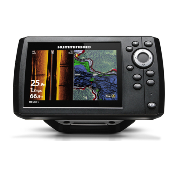
What’s on the Control Head Your HELIX Series user interface is easy to use. A combination of keys, different views, and situation-specific, customizable menus allows you to control what you see on the color display. Refer to the following illustration and see Key Functions, Views, and The Menu System for more information. -
Page 21: Key Functions
Key Functions Your Fishfinder user interface consists of a set of easy-to-use keys that work with various on- screen views and menus to give you flexibility and control over your fishing experience. POWER/LIGHT Key The POWER/LIGHT key is used to power the Fishfinder on and off. You can also use the POWER/LIGHT key to adjust the backlight and contrast of the display. -
Page 22: Menu Key
MENU Key The MENU key is used to access the menu system. See The Menu System for more information. • Start-Up Options Menu: Press the MENU key during the power up sequence to view the Start-Up Options menu. • X-Press Menu: Press the MENU key once in any view to access the X-Press Menu, which provides frequently-used menu settings that correspond with the current view or navigation mode. -
Page 23: Mark Key
MARK Key Press the MARK key while in any view to mark the position of a waypoint. The MARK key function works if you have the GPS receiver connected. • Active Cursor: The waypoint will be marked at the cursor location. •... -
Page 24: Zoom (+/-) Key
ZOOM (+/–) Key The Zoom (+/–) key has multiple functions, depending on the situation: • In any of the Navigation Views or the Sonar Zoom View, press the +/– Zoom key to change the scale of the view to appear closer or farther away. See Views and Introduction to Navigation for more information. -
Page 25: Micro Sd Card Slot
(see Snapshot and Recording View for details). NOTE: The Micro SD Card requires a separate purchase. For more information, visit our Web site at humminbird.com or contact Humminbird Customer Service at 1-800-633-1468. To insert a Micro SD Card: 1. Remove the Micro SD Card slot cover. -
Page 26: Add Maps To Your Fishfinder
Add Maps to Your Fishfinder Your Fishfinder includes a built-in UniMap with a more detailed map of North America (Domestic models) or a detailed map of Europe and Southeast Asia, including Australia and New Zealand (International models). You can also purchase Micro SD Cards with additional chart information for a particular location. NOTE: The Micro SD Cards require a separate purchase. -
Page 27: Import Navigation Data
Review the following information before importing navigation data (waypoints, routes, tracks, or groups) into your Humminbird unit. • Import Humminbird Navigation Data: Insert a loaded Micro SD Card into the control head card slot, and follow the on-screen prompts to import the waypoints, routes, tracks, and groups. - Page 28 NOTE: If a Micro SD Card is not installed, an error message will be displayed. Insert the card and try again. NOTE: The Micro SD Card and adapter require separate purchases. Visit our Web site at humminbird.com or contact Humminbird Customer Service at 1-800-633-1468. Micro SD Card Slot...
-
Page 29: Update Software
Update Software Set up an online account at humminbird.com so that you will receive the latest Humminbird news and software updates for your Fishfinder. You can also download HumminbirdPC from your account, which allows you to manage your waypoints, routes, and tracks on your personal computer. -
Page 30: What's On The Sonar Display
What’s on the Sonar Display The Fishfinder can display a variety of useful information about the area under and adjacent to Depth - Water depth can be set to alarm when the water becomes too shallow. Timer - Elapsed time with Speed accessory or GPS receiver Distance - Distance traveled with Speed accessory or GPS receiver Average Speed - Average speed reading with Speed accessory or GPS receiver What’s on the Sonar Display... - Page 31 your boat, including the following items: Thermoclines - Layers of water with different temperatures that appear at different depths and different times of the year. A thermocline typically appears as a continuous band of many colors moving across the display at the same depth. Sonar Color Bar - Color spectrum indicating low to high sonar intensity returns, where red indicates high intensity and white indicates low intensity.
-
Page 32: Understanding The Sonar Display
Understanding the Sonar Display It is important to understand the significance of the display. The display does NOT show a literal 3-dimensional representation of what is under the water. Each vertical band of data received by the control head and plotted on the display represents something that was detected by a sonar return at a particular time. -
Page 33: Sonar Colors And Bottom View
Sonar Colors and Bottom View Sonar Colors: Original Palette As the boat moves, the unit charts the changes in depth on HIGH the display to create a profile of the Bottom Contour. The intensity return Sonar View displays the sonar return intensity with different colors. - Page 34 Use Bottom View to select the method used to represent bottom and structure on the display. See Sonar Menu to set the Bottom View. Structure ID represents weak returns in blue and strong returns in red when Sonar Colors is set to Original.
-
Page 35: Switchfire
SwitchFire SwitchFire controls how the sonar returns are displayed in the Sonar Views. SwitchFire settings are available in the Sonar Menu Tab. To see the maximum sonar information available within the transducer beam so more fish arches and better jig tracking are shown, choose Max Mode. To see less clutter and more fish size accuracy interpreted from the transducer beam, choose Clear Mode. -
Page 36: What's On The Side Imaging Display
What’s on the Side Imaging Display Side Imaging displays a number of easily recognizable features that allow for accurate interpretation of sonar return. For example, rock and gravel provide a clearer sonar return than mud and sand because of face away from the transducer. You can find a number of easily recognizable features on the Side Imaging Depth - Water depth can be set to alarm when the water becomes too shallow. - Page 37 bottom contour and structure. For Side Imaging, the bottom composition determines the intensity of the their relative density. Upward slopes that face the transducer reflect sonar better than downward slopes that display that allow for accurate interpretation of bottom contour and structure, including the following items: Shadows - result from a lack of reflected sonar from a particular area and can be more valuable for interpretation than the sonar reflected by the object...
-
Page 38: Understanding The Side Imaging Display
Understanding the Side Imaging Display It is important to understand how Side Imaging technology produces the display. The images you see on the display are produced using sonar technology. The special transducer projects three distinct beams – one beam facing down and two beams pointing out to the side. Down Beam is aimed directly below the boat and provides conical coverage. -
Page 39: Side Imaging Frequencies And Coverage
Side Imaging sonar echoes are first displayed at the top of the screen, and historical data scrolls down the display as new information is received. The main benefit of Side Imaging sonar to anglers is that it provides an overall survey of a large area of water. -
Page 40: For Best Performance
See Submerged Bridge: Creek Channel and New Bridge Pilings and the Submerged Bridge: Alternative Perspective illustrations for examples of this. See humminbird.com for a side imaging sonar tutorial and additional information. What’s on the Side Imaging Display... -
Page 41: On The Water Interpretation
On the Water Interpretation Submerged Bridge, Creek Channel and New Bridge Pilings new bridge pilings submerged bridge creek channel Submerged Ravine with Timber submerged timber submerged ravine submerged tree possible drop off What’s on the Side Imaging Display... - Page 42 Submerged Bridge, Alternative Perspective submerged bridge Submerged Standing and Fallen Timber, plus Bait Fish bait fish standing and fallen timber What’s on the Side Imaging Display...
- Page 43 Submerged Swimming Pool swimming pool Submerged Barge with Dumped Logs dumped logs submerged barge What’s on the Side Imaging Display...
-
Page 44: What's On The Down Imaging Display
What’s on the Down Imaging Display Down Imaging uses unique sonar technology to provide information about the area directly that you see on the display. Down Imaging reveals a variety of recognizable features so that you Depth - Water depth can be set to alarm when the water becomes too shallow. Timer - Elapsed time with Speed accessory or GPS receiver Distance - Distance traveled with Speed accessory or GPS receiver Average Speed - Average speed reading with Speed accessory or GPS receiver... - Page 45 below your boat. The razor-thin, high- definition profiling beams produce the detailed sonar data can interpret the structure and bottom contour, including the following items: Shadows - result from a lack of reflected sonar from a particular area and can be as valuable for interpretation than the sonar reflected by the object itself.
-
Page 46: Understanding The Down Imaging Display
Understanding the Down Imaging Display The images you see on the Down Imaging display are produced using sonar technology. Each time the unit pings, a strip of data representing all the echoes received by the transducer are put together on the display to form the image that you see. -
Page 47: Views
Combo View, which shows two views on the screen at the same time. • Available Views: The available Views on your Humminbird unit will vary with the model and the transducer attached to your control head. See Views Menu Tab and the following pages for more information. -
Page 48: Sonar View
Sonar View Sonar View presents a historical log of sonar returns. The most recent sonar returns are charted on the right side of the display. As new information is received, the historical information scrolls left across the display. • Upper and Lower Depth Range numbers indicate the distance from the surface of the water to a depth range sufficient to show the bottom. -
Page 49: Sonar Zoom View
Sonar Zoom View Sonar Zoom View provides a magnified view of the bottom and structure. The Sonar Zoom View makes it easier to see separate sonar returns that would usually be displayed close together, such as those caused by fish suspended close to the bottom or within structure. •... -
Page 50: Split Sonar View
Split Sonar View Split Sonar View displays sonar returns from each down beam frequency on separate sides of the screen. You can use the Split Sonar View to make side by side comparisons between the sonar returns from both beams. •... -
Page 51: Big Digits View
Big Digits View Big Digits View provides digital data in a large, easy-to-see format. • Digital Readouts: Readouts for depth, temperature, and speed information are displayed automatically if the transducer with built-in temperature and GPS receiver are connected to the Fishfinder. •... -
Page 52: Circular Flasher View
Circular Flasher View Circular Flasher View provides two ways to view sonar data in traditional flasher format. The view is controlled by the Ice Fishing Mode menu option in the Sonar Menu Tab. • When Ice Fishing Mode is off, the Circular Flasher View displays Real Time Sonar (RTS) data in a traditional flasher format. - Page 53 Ice Fishing Mode: Off When Ice Fishing Mode is off, the Circular Flasher View displays Real Time Sonar (RTS) data in a traditional flasher format. • Flasher X-Press Menu: Press the MENU key once in the Circular Flasher View. Use the X-Press Menu to set the Sensitivity, Upper Range, and Lower Range.
- Page 54 Ice Fishing Mode: On When Ice Fishing Mode is on, the Circular Flasher View displays the sonar data in traditional flasher format with additional features including Zoom and Depth Cursor. • Sensitivity: When you turn on Ice Fishing Mode, the Fishfinder’s sensitivity settings are adjusted automatically to accommodate ice fishing conditions.
- Page 55 To activate the Depth Cursor: Use the Depth Cursor to identify depth on the flasher display. 1. Set up: Press the VIEW key repeatedly until the Circular Flasher View is displayed on the screen. Turn on the Ice Fishing Mode (see Sonar Menu Tab). 2.
- Page 56 To activate Flasher Zoom: The Zoom feature displays a 2x magnified view of the area you choose on the flasher display. 1. Set up: Press the VIEW key repeatedly until the Circular Flasher View is displayed on the screen. Turn on the Ice Fishing Mode (see Sonar Menu Tab). 2.
-
Page 57: Side Imaging View
Side Imaging View Side Imaging View shows a shadowed right- and left-looking view from the boat as the boat passes over the bottom. See What’s on the Side Imaging Display and Understanding the Side Imaging Display for more information about interpreting the Side Imaging View. •... - Page 58 Side Imaging View (while navigating) depth topography changes course bottom return speed orange boat icon waypoint the boat is navigating towards water column shadows Views...
- Page 59 Side Imaging View, with Active Cursor and Zoom depth shadows triplog topography changes water surface temperature bottom return zoom box speed water column Views...
-
Page 60: Down Imaging View
Down Imaging View Down Imaging View displays the down beam portion of the data from the Side Imaging beams. The Down Imaging results are displayed in 2D format. Sonar returns are charted on the right side of the display. As new information is received, the historical information scrolls left across the display. - Page 61 Down Imaging View with Active Cursor and Zoom depth shadows triplog topography changes voltage bottom return zoom box speed structure NOTE: To change the colors used to display the Down Imaging data on the screen, see Down Imaging X-Press Menu: Imaging Colors. Views...
-
Page 62: Snapshot And Recording View (Optional-Purchase Micro Sd Card Required)
Snapshot and Recording View (optional-purchase Micro SD Card required) Snapshot and Recording View displays the screen snapshots and recordings that are saved on the optional-purchase Micro SD Card installed in the control head. Use this view to review the snapshot and recording file details, start recording, and adjust the recording settings. •... -
Page 63: Screen Snapshots
Screen Snapshots Screen Snapshots are saved pictures of the view on the screen. The screen snapshot will include the menus, dialog boxes, warnings, and messages that were active when the screen snapshot was taken. Saved Screen Snapshots can be viewed from the Snapshot and Recording View or Chart View. - Page 64 Micro SD Card (see humminbird.com for details). You will notice that a .DAT (or a .TXT) file is created for every .PNG screen snapshot. This data file is required for viewing the screen snapshots from your control head, so don’t delete these files.
- Page 65 Recording and Playback The Recording feature records active sonar information. When the recording is played back, the views that were active during the recording are available in Playback. The Recording and Playback feature is available when an optional-purchase Micro SD Card is installed and Screen Snapshot is On (see Setup Menu Tab: Screen Snapshot).
- Page 66 Playback a Recording: 1. From the Snapshot and Recording View, press the UP or DOWN Cursor keys to scroll through the saved files and highlight a saved Recording. 2. Press the RIGHT Cursor key. recording file information highlighted recording file Change Playback Settings: 1.
- Page 67 Notes about Playback: • “Playback” will flash periodically on the screen to indicate that the control head is playing a saved recording and not a “live” view. • Navigation is not affected by the Sonar Recording feature, but any active navigation is cancelled and thumbnails and icons disappear when Playback begins or ends.
-
Page 68: Bird's Eye View
Bird’s Eye View Bird’s Eye View shows a 3D perspective view of the track and the chart’s land contour from a point above and behind the boat (the eye point). As the boat turns, the eye point moves to follow the boat. - Page 69 Bird's Eye View (Navigating) next waypoint latitude and longitude position off course limits speed of the boat route XTE (Cross Track Error): distance of boat from route track course over ground (COG) depth Bearing: direction to destination waypoint measured in degrees from North time to go (TTG) to the next waypoint in the route DTG: distance to go to waypoint Views...
-
Page 70: Chart View
Chart View Chart View shows cartography from the built-in UniMap or an optional Micro SD Card map for the area surrounding your current position. The cartography is applied to any standard Chart View or Combo view that displays a chart. The current track (also known as the position history or breadcrumb trail) showing where the boat has been, along with saved tracks, waypoints, and the current route (when navigating), are overlaid on the chart. -
Page 71: Combo Views
Combo Views Combo Views display two views (or more) on the screen at the same time. You can perform functions for either side of the view, access the X-Press Menu, and change the left view display size. The available combo views are shown on the following pages. Combo Views: Functions The Combo Views allow you to observe and control two views at once. -
Page 72: Chart/Bird's Eye Combo View
Chart/Bird’s Eye Combo View Chart/Bird’s Eye Combo View shows the Chart and Bird’s Eye views in a combination split screen, where the Bird’s Eye View is displayed on the left and the Chart View is displayed on the right. For more information about each side of this combo view, see Chart View and Bird’s Eye View. -
Page 73: Chart/Chart Combo View
Chart/Chart Combo View Chart/Chart Combo View shows two versions of the Chart view in a combination split screen so that you can see the position of the boat on one side while you zoom in or perform other functions on the other. See Chart View for more information. Chart/Chart Combo View with Active Cursor latitude and longitude position of cursor depth... -
Page 74: Chart/Sonar Combo View
Chart/Sonar Combo View Chart/Sonar Combo View shows both the Chart and Sonar views in a combination split screen, where the Sonar View is displayed on the left and the Chart View is displayed on the right. For more information about each side of this combo view, see Chart View and Sonar View. Chart/Sonar Combo View depth boat icon... -
Page 75: Chart/Side Imaging Combo View
Chart/Side Imaging Combo View Chart/Side Imaging Combo View shows chart information and Side Imaging sonar information in a combination split screen, where the Side Imaging View is displayed on the left and the Chart View is displayed on the right. For more information about each side of this combo view, see Chart View and Side Imaging View. -
Page 76: Chart/Down Imaging Combo View
Chart/Down Imaging Combo View Chart/Down Imaging Combo View shows Chart and Down Imaging information in a combination split screen, where the Down Imaging View is displayed on the left and the Chart View is displayed on the right. For more information about each side of this combo view, see Down Imaging View and Chart View. -
Page 77: Side Imaging/Sonar Combo View
Side Imaging/Sonar Combo View Side Imaging/Sonar Combo View shows sonar information and Side Imaging sonar information in a combination split screen, where the Sonar View is displayed on the left and the Side Imaging View is displayed on the right. Select an Active Side, and you can adjust the sensitivity, the side beam range, the chart scrolling speed, and the color scheme of the display. -
Page 78: Side Imaging/Down Imaging Combo View
Side Imaging/Down Imaging Combo View Side Imaging/Down Imaging Combo View shows Side Imaging and Down Imaging sonar information in a combination split screen, where the Down Imaging View is displayed on the left and the Side Imaging View is displayed on the right. For more information about each side of this combo view, see Down Imaging View and Side Imaging View. -
Page 79: Down Imaging/Sonar Combo View
Down Imaging/Sonar Combo View Down Imaging/Sonar Combo View shows traditional Sonar information on the left and Down Imaging sonar information on the right. For more information about each side of this combo view, see Down Imaging View and Sonar View. Down Imaging/Sonar Combo View digital readouts depth lines... -
Page 80: Side Imaging/Down Imaging/Sonar Combo View
Side Imaging/Down Imaging/Sonar Combo View Side Imaging/Down Imaging/Sonar Combo View shows Down Imaging and traditional Sonar information on the left side of the screen, and Side Imaging on the right side of the screen. If you use the active cursor on the left side of the screen, a cursor will appear in both the Sonar and Down Imaging views. -
Page 81: Chart View Orientation
Chart View Orientation Both Chart and Chart Combo Views allow you to choose the orientation of the view (see Navigation Menu Tab: Chart Orientation). In each orientation, the view pans automatically so that the boat is always centered on the display. To see more of the view when the boat is traveling at the speed you set, see Chart Menu Tab: Vessel Offset and Offset Speed. -
Page 82: Viewing Cartography
Viewing Cartography In the Chart and Chart Combo Views, there are several cartography-related functions that you can access using various keys. Panning: Use the 4-WAY Cursor Control key to move the chart around on the display in the direction of the key being pressed. When you do this, a bull’s eye cursor is drawn at the center of the screen and is linked to the boat by a yellow line, even if the boat is off the screen. - Page 83 Screen Snapshots and Recording Icons: When a waypoint is created while Screen Snapshot and Recording is active, the waypoint will appear as a snapshot icon or recording icon in chart views. See Views: Snapshot and Recording View for more information. Chart Info: Press the CHECK/INFO key to get detailed information about the chart.
-
Page 84: Introduction To Navigation
You can also use the Waypoint Management dialog box to create new waypoints and routes from scratch. You can edit your navigation data and organize it too. This section will get you started. See your Humminbird Waypoint Management Guide for complete details. Waypoints, Routes, and Tracks... -
Page 85: Open The Waypoint Management Dialog Box
Dialog Box The Waypoint Management dialog box allows you to organize your waypoints, routes, and tracks on your Humminbird control head. Open the Waypoint Management Dialog Box 1. Press the MENU key twice to open the Main Menu. 2. Press the RIGHT Cursor key until the Navigation Menu Tab is selected. -
Page 86: What's On The Waypoint Management Dialog Box
What’s on the Waypoint Management Dialog Box Use the Waypoint Management dialog box to manage your waypoints, routes, and tracks. Use the 4-WAY Cursor Control key to select a waypoint, route, track, group, or menu option. To scroll through the list, press the UP or DOWN Cursor keys. To open a submenu, press the RIGHT Cursor key. - Page 87 Information: Displays the default group where all new waypoints, routes, and tracks will be saved. In this illustration, Home is the default group. This field also changes to display instructions. Directory: Shows the directory structure and the currently selected group. The illustration shows group GP070 as the selected group.
-
Page 88: Save, Edit, Or Delete A Waypoint
Save, Edit, or Delete a Waypoint Save your Current Position as a Waypoint: On any view, press the MARK key to save the current position of the boat as a waypoint. Save the Cursor Position as a Waypoint: On the Chart or Chart Combo Views, use the 4-WAY Cursor Control key to move the cursor to the position you want to save as a waypoint. -
Page 89: Add A Waypoint Target Or Trolling Grid
Add a Waypoint Target or Trolling Grid The Waypoint Target shows a target consisting of concentric circles in various distance ranges centered on the waypoint you choose. The Trolling Grid shows various distance ranges in grid format from the waypoint you choose. The trolling grid can be used as a guide when trolling around a waypoint. -
Page 90: Routes
Routes Save the Current Route: While you are navigating, the current route can be saved. From the Navigation X-Press Menu, select Save Current Route, and press the RIGHT Cursor key. Navigation will continue. Create a New Route: Open the Waypoint Management dialog box. Select Options > New > New Route. - Page 91 • Choose a Waypoint in a Route, and press the RIGHT Cursor key. Select Reorder, and press the RIGHT Cursor key. To move the waypoint up or down in the route order, press the UP or DOWN Cursor keys. Press the EXIT key to select Save. Press the RIGHT Cursor key to confirm your changes. Changing the Waypoint Order in a Route (two options) Select Reverse OR Select a Waypoint >...
-
Page 92: Tracks
NOTE: The Edit Waypoint dialog box is also available when you select a waypoint from the Navigation X-Press Menu. NOTE: See your Humminbird Waypoint Management Guide for more information about groups and the other great features of the Waypoint Management dialog box. - Page 93 Edit a Waypoint, Route, Track, or Group 1. Open the Waypoint Management dialog box. 2. Open the Submenu: Use the 4-WAY Cursor Control key to select a waypoint, route, track, or group. Press the RIGHT Cursor key to open the submenu. 3.
-
Page 94: Man Overboard (Mob) Navigation
Man Overboard (MOB) Navigation As soon as you know that you have a man overboard (MOB), you should activate MOB navigation to maximize the chances for a successful rescue. MOB navigation allows you to create an MOB waypoint to locate the point at which your man went overboard and the relation of the boat to that point. - Page 95 MOB Navigation position where man fell overboard target surrounding MOB waypoint MOB waypoint elapsed time since MOB was activated boat icon It is not possible to re-activate MOB or modify the current route without first canceling MOB navigation. The Off Course trigger is also disabled and the Off Course Alarm circle is not drawn. Any press of the GOTO key, or selection of a GOTO menu option, will cause an error beep and a short message will be displayed that will disappear after 2 seconds.
-
Page 96: The Menu System
The Menu System The Menu System is divided into easy-to-use menu modules as follows: • Start-Up Options Menu: Press the MENU key during the power on sequence to view the Start-Up Options Menu. From the Start-Up Options Menu, you can choose the following Fishfinder Modes: Normal, Simulator, and System Status. -
Page 97: Start-Up Options Menu
Start-Up Options Menu Press the MENU key during the power on sequence to view the Start-Up Options Menu, and select one of the modes described on the following pages. Also, see Power On for more information. Start-Up Options Menu Normal Use Normal for on-the-water operation with a transducer connected. -
Page 98: Simulator
Simulator Use Simulator to learn how to use your Fishfinder before taking your boat on the water. The Simulator is a very powerful tool that provides a randomly-updated display which simulates on the water operation. Simulator We recommend going through this manual while using the Simulator, since all of the menus function and affect the display in the same way as they would in Normal operation. -
Page 99: System Status
System Status Use System Status to view system connections and to conduct a unit self-test. After you select System Status from the Start-Up Options Menu, press the VIEW key to display the following options: • Self Test • Accessory Test •... -
Page 100: Gps Diagnostic View
NOTE: The speed accessory will be detected only if the paddlewheel has moved since your Fishfinder was powered up. GPS Diagnostic View shows a sky chart and numerical data from the GPS receiver. The sky chart shows the location of each visible GPS satellite with its satellite number and a signal strength bar. A dark gray bar indicates that the satellite is being used to determine your current position. -
Page 101: X-Press Menu
X-Press Menu The X-Press Menu provides a shortcut to your most frequently-used settings. The options provided on the X-Press Menu correspond with the current view. For example, if you are in a Sonar View and press the MENU key once, the Sonar X-Press Menu will display. X-Press Menu To use an X-Press Menu: 1. -
Page 102: Main Menu
Main Menu The Main Menu provides the standard set of menu options, including the settings that are changed less frequently. The Main Menu is organized under the following tabs to help you find a specific menu item quickly: Alarms, Sonar, Navigation, Chart, Setup, and Views. -
Page 103: Quick Tips For The Main Menu
Quick Tips for the Main Menu • From any menu option on a menu tab, press the EXIT key to jump directly to the top of the tab. • From the bottom of a menu tab, press the DOWN Cursor key to jump directly to the top of the tab. -
Page 104: User Mode (Normal Or Advanced)
User Mode (Normal or Advanced) Menu options can be simplified or expanded by setting your Fishfinder User Mode to Normal or Advanced. Normal Mode is provided for users who want greater simplicity and fewer menu choices. Advanced Mode is provided for users who want the highest level of control over the Fishfinder. Several menu settings are added to the Main Menu when the User Mode is changed to Advanced. - Page 105 Sonar Tab, Normal Mode Sonar Tab, Advanced Mode Main Menu...
-
Page 106: Sonar X-Press Menu
Sonar X-Press Menu The Sonar X-Press Menu provides a shortcut to your most frequently-used settings. Press the MENU key once while in any of the Sonar Views to access the Sonar X-Press Menu. NOTE: Menu options can be expanded or simplified by setting the User Mode to Advanced or Normal. -
Page 107: Cancel Navigation (Only When Navigating)
Cancel Navigation (only when Navigating) Settings: Press the RIGHT Cursor key and follow screen instructions. Cancel Navigation discards the current route and exits Navigation Mode. This menu option will only appear when you are currently navigating a route. This will not delete a previously-saved route. -
Page 108: Sensitivity
Sensitivity Settings: Low = 1, High = 20; Default = 10 Sensitivity controls how much detail is shown on the display and will adjust the sensitivity of all sonar frequencies. Decrease the sensitivity to eliminate the clutter from the display that is sometimes present in murky or muddy water. -
Page 109: Lower Range
Lower Range Settings: Auto to 1500 feet, Auto to 500 meters (International Models only); Default = Auto Lower Range sets the deepest depth range that will be displayed by the unit. Auto: The Lower Range will be adjusted by the unit to follow the bottom automatically. Auto is the default setting. -
Page 110: Bottom Range (Sonar Zoom View Only, When Bottom Lock Is On)
Bottom Range (Sonar Zoom View only, when Bottom Lock is On) Settings: 10 to 60 feet, 2 to 10 fathoms, or 3 to 20 meters [International Models only]; Default = 15 feet Bottom Range allows you to control how much of the water column, measured up from the bottom, is shown in the Sonar Zoom View. -
Page 111: Flasher X-Press Menu (Circular Flasher View Only)
Flasher X-Press Menu (Circular Flasher View only) The Flasher X-Press Menu provides a shortcut to your most frequently-used settings. Press the MENU key once while in the Circular Flasher View to access the Flasher X-Press Menu. NOTE: Menu options will vary depending on system settings, such as whether you are currently navigating. -
Page 112: Cancel Navigation (Only When Navigating)
Cancel Navigation (only when Navigating) Settings: Press the RIGHT Cursor key and follow screen instructions. Cancel Navigation discards the current route and exits Navigation Mode. This menu option will only appear when you are currently navigating a route. This will not delete a previously-saved route. -
Page 113: Color Palette (Circular Flasher View, Ice Fishing Mode Only)
Color Palette (Circular Flasher View, Ice Fishing Mode only) Settings: Palette 1, Palette 2, Palette 3; Default = Palette 3 Color Palette sets the colors used to display sonar returns in the Circular Flasher View when Ice Fishing Mode is turned on. The active color palette is shown in the center of the circular flasher display. -
Page 114: Snapshot And Recording X-Press Menu (Snapshot And Recording View Only)
Snapshot and Recording X-Press Menu (Snapshot and Recording View only) The Snapshot and Recording X-Press Menu provides access to the snapshot management and sonar recording functions. Press the MENU key once while in the Snapshot and Recording View to access the Snapshot and Recording X-Press Menu. -
Page 115: Cancel Navigation (Only When Navigating)
Cancel Navigation (only when Navigating) Settings: Press the RIGHT Cursor key and follow screen instructions. Cancel Navigation discards the current route and exits Navigation Mode. This menu option will only appear when you are currently navigating a route. This will not delete a previously-saved route. -
Page 116: Delete All Recordings (Optional-Purchase Micro Sd Card, Snapshot And Recording View Only)
Delete All Recordings (optional-purchase Micro SD Card, Snapshot and Recording View only) Settings: Press the RIGHT Cursor key and follow screen instructions. Delete All Recordings allows you to delete all the recordings at once. This menu option is only available when an optional-purchase Micro SD Card is installed and Snapshot and Recording View is on the screen. -
Page 117: Stop Playback (Optional-Purchase Micro Sd Card Only)
NOTE: Sonar chart speed is increased during Fast Forward and reversed during Rewind. This may result in a reduced quality sonar image, since at higher speeds, not every sonar return can be processed. Stop Playback (optional-purchase Micro SD Card only) Settings: Press the RIGHT Cursor key to activate. -
Page 118: Side Imaging X-Press Menu (Side Imaging Views Only)
Side Imaging X-Press Menu (Side Imaging Views only) The Side Imaging X-Press Menu provides a shortcut to your most frequently-used settings. Press the MENU key once while in any of the Side Imaging Views to access the Side Imaging X-Press Menu. NOTE: Menu options can be expanded or simplified by setting the User Mode to Advanced or Normal. -
Page 119: Cancel Navigation (Only When Navigating)
Cancel Navigation (only when Navigating) Settings: Press the RIGHT Cursor key and follow screen instructions. Cancel Navigation discards the current route and exits Navigation Mode. This menu option will only appear when you are currently navigating a route. This will not delete a previously-saved route. Active Side (Combo Views only) Settings: Left, Right;... -
Page 120: Si Enhance
SI Enhance Settings: Press the RIGHT Cursor key. SI Enhance allows you to adjust your Side Imaging View in four categories: Sensitivity, Contrast, Sharpness, and Contour Mode. Whether you’re searching the Side Imaging data for fish or certain bottom contour, the most effective settings will vary with the situation. -
Page 121: Si Range
SI Range Settings: Auto, 7 to 360 feet, or 3 to 120 meters [International Models only]; Default = 150 feet, 50 meters SI Range sets the deepest range that will be displayed in the Side Imaging views. The range must be set manually. Choose a low range number to focus on a shorter distance of the water column and see greater detail on the screen. -
Page 122: Down Imaging X-Press Menu (Down Imaging Views Only)
Down Imaging X-Press Menu (Down Imaging Views only) The Down Imaging X-Press Menu provides a shortcut to your most frequently-used settings. Press the MENU key once while in any of the Down Imaging Views to access the Down Imaging X-Press Menu. NOTE: Menu options can be expanded or simplified by setting the User Mode to Advanced or Normal. -
Page 123: Cancel Navigation (Only When Navigating)
Cancel Navigation (only when Navigating) Settings: Press the RIGHT Cursor key and follow screen instructions. Cancel Navigation discards the current route and exits Navigation Mode. This menu option will only appear when you are currently navigating a route. This will not delete a previously-saved route. -
Page 124: Di Enhance
DI Enhance Settings: Press the RIGHT Cursor key. DI Enhance allows you to adjust your Down Imaging View in the following categories: Sensitivity, Contrast, and Sharpness. Whether you’re searching the Down Imaging data for fish or certain bottom contour, the most effective settings will vary with the situation. -
Page 125: Lower Range
Lower Range Settings: Auto to 1500 feet, Auto to 500 meters [International Models only]; Default = Auto Lower Range sets the deepest depth range that will be displayed by the unit. Auto: The Lower Range will be adjusted by the unit to follow the bottom automatically. Auto is the default setting. -
Page 126: Navigation X-Press Menu
NOTE: To see the Navigation X-Press Menu in a Combo View, change the Active Side setting to the side you want to adjust. Navigation X-Press Menu See Introduction to Navigation and the Humminbird Waypoint Management Guide for more information. Navigation X-Press Menu... -
Page 127: Cancel Navigation (Only When Navigating)
Cancel Navigation (only when Navigating) Settings: Press the RIGHT Cursor key and follow screen instructions. Cancel Navigation discards the current route and exits Navigation Mode. This menu option will only appear when you are currently navigating a route. This will not delete a previously-saved route. -
Page 128: Waypoint [Name] (Only With An Active Cursor On A Waypoint)
You can move the cursor onto an existing waypoint and press the MENU key once, or use Cursor to Waypoint to select a waypoint from the saved waypoints list. NOTE: See Introduction to Navigation and the Humminbird Waypoint Management Guide for more information. -
Page 129: Clear Current Track
Clear Current Track Settings: Press the RIGHT Cursor key and follow screen instructions. Clear Current Track allows you to clear the current track on the display and start a new track at the present position. Save Current Route (only when Navigating) Settings: Press the RIGHT Cursor key and follow screen instructions. -
Page 130: Waypoint [Name] (Most Recently-Created Waypoint)
You must have pressed the MARK key at least once since you last powered up the Fishfinder for this menu option to appear. NOTE: See Introduction to Navigation and the Humminbird Waypoint Management Guide for more information. The Waypoint Submenu includes the following menu options: Edit opens the Edit Waypoint dialog box so that you can edit the selected waypoint. -
Page 131: Alarms Menu Tab
Alarms Menu Tab From any view, press the MENU key twice to access the Main Menu System. The Alarms tab will be the default selection. NOTE: When an alarm is triggered, you can silence it by pressing any key. The alarm will be silenced, and will not be triggered again until a new instance of the alarm condition is detected. -
Page 132: Depth Alarm
Depth Alarm Settings: Off, 1 to 100 feet, or 0.5 to 30 meters [International Models only]; Default = Off Depth Alarm sounds when the depth becomes equal to or less than the menu setting. Fish ID Alarm Settings: Off, All, Large/Medium, Large; Default = Off Fish ID Alarm sounds when the Fishfinder detects fish that correspond to the alarm setting. -
Page 133: Off Course Alarm
Off Course Alarm Settings: Off, 25 to 3000 feet, 10 to 1000 meters [International Models only]; Default = 300 feet, 100 meters Off Course Alarm allows you to set how far the boat is allowed to move off course before the Off Course Alarm will sound during navigation. -
Page 134: Alarm Tone
Alarm Tone Settings: High, Medium, Low; Default = Medium Alarm Tone selects the pitch of the alarm sound. A brief tone will be produced as you adjust the Alarm Tone so that you can select the tone that you can hear best. Timer Setup Settings: Press the RIGHT Cursor key to open the dialog box. -
Page 135: Sonar Menu Tab
Sonar Menu Tab Press the MENU key twice to access the Main Menu and then press the RIGHT Cursor key until the Sonar tab is selected. NOTE: Menu options can be expanded or simplified by setting the User Mode to Advanced or Normal. See Main Menu: User Mode for details. -
Page 136: Beam Select
Beam Select Settings: 200/83 kHz, 200 kHz, 83 kHz; Default = 200 kHz Beam Select sets which sonar returns from the transducer will be displayed on the screen. • When set to 200/83 kHz, the returns from both beams are blended by starting with the 83 kHz wide beam return, dimming it, and then overlaying it with the 200 kHz narrow beam return. -
Page 137: Switchfire
SwitchFire Settings: Max Mode, Clear Mode; Default = Clear Mode SwitchFire controls how the sonar returns are displayed in the Sonar Views. Choose Max Mode to see only raw sonar returns on the display. When Max Mode is selected, you will see the maximum sonar information available within the transducer beam, so more fish arches and better jig tracking are shown. -
Page 138: Fish Id Sensitivity
Fish ID Sensitivity Settings: Low = 1, High = 10; Default = 5 Fish ID Sensitivity adjusts the threshold of the Fish ID+ detection algorithms. Selecting a higher setting allows weaker returns to be displayed as fish. This is useful for identifying smaller fish species or baitfish. -
Page 139: Bottom View
Bottom View Settings: Structure ID, WhiteLine; Default = Structure ID Bottom View selects the method used to represent bottom and structure on the display. • Structure ID represents weak returns in blue and strong returns in red. If the Sonar Colors palette is changed, the Structure ID will display the strongest return as specified by the palette. -
Page 140: Si Range Lines (Advanced, Side Imaging View Only)
SI range lines SI range lines NOTE: The illustrations in this manual may not look exactly like the display on your Humminbird model, but the view will work in a similar way. SI Readouts (Side Imaging View only) Settings: Off, On;... -
Page 141: Noise Filter (Advanced)
Noise Filter (Advanced) Settings: Off, Low, Medium, High 1, High 2, High 3; Default = Low Noise Filter adjusts the sonar Noise Filter to limit interference on the display from sources such as your boat engine, turbulence, or other sonar devices. The Off setting removes all filtering. -
Page 142: Color Bar
Color Bar Settings: Off, On; Default = On Color Bar allows you to display or suppress the display of the color bar shown in the full screen Sonar View. Down Imaging Beam Width (Advanced, Down Imaging Views only) Settings: Narrow, Medium, Wide; Default = Wide Down Imaging Beam Width controls the width of the beam (side to side) for the Down Imaging View and sets the amount of information shown on the display. -
Page 143: Navigation Menu Tab
Navigation Menu Tab Press the MENU key twice to access the Main Menu, then press the RIGHT Cursor key until the Navigation tab is selected. NOTE: Menu options will vary depending on system settings, such as whether you are currently navigating. NOTE: Menu options can be expanded or simplified by setting the User Mode to Advanced or Normal. -
Page 144: Current Track
You can also edit waypoint, route, and track information. Your navigation data can be saved into groups, sorted, copied, and exported to HumminbirdPC. See Introduction to Navigation and the Humminbird Waypoint Management Guide for more information. Navigation Menu Tab... -
Page 145: Waypoint Settings
Settings dialog box to set the waypoint icon category and the waypoint icon for all new waypoints. See Introduction to Navigation: Edit your Waypoints, Routes, Tracks, and Groups and the Humminbird Waypoint Management Guide for details. The Waypoint Settings dialog box includes the following options: Icon Category allows you to select a waypoint icon category (All, Geometry, Alerts, Supplies, Navigation, Recreation, Fish, Environment). -
Page 146: Casting Rings
Casting Rings Settings: Off to 150 feet, 0 to 50 meters; Default = Off Casting Rings allows you to display a circle around each waypoint on the Chart View. This menu option sets the distance that the Casting Ring will be displayed from the waypoint. Select Off to hide the Casting Rings. -
Page 147: Waypoint Decluttering (Advanced)
Waypoint Decluttering (Advanced) Settings: Off, On; Default = On Waypoint Decluttering allows you to set the declutter feature On or Off. When two or more waypoints overlap, or are displayed close together on a chart view, the screen will automatically declutter—waypoint names will shorten and the waypoint icons will change into small blue icons. -
Page 148: Track Color Range
Track Color Range Settings: 50 to 3000* feet or 20 to 1000 meters [International Units only], Default = 50 feet, 20 meters Track Color Range allows you to set the depth range that will be displayed as black, the deepest depth, when Color By Depth is selected as the style for the current track (see Navigation Menu Tab: Current Track). -
Page 149: Continuous Navigation Mode
Continuous Navigation Mode Settings: Off, On; Default = Off Continuous Navigation Mode allows you to continue to navigate and fish around a particular waypoint, even if you pass over it multiple times. GPS Receiver Override (Advanced) Settings: Internal, External, Auto; Default = Auto GPS Receiver Override allows you to set which GPS receiver to use if you have multiple GPS receivers plugged into the system. -
Page 150: Chart Menu Tab
Chart Menu Tab Press the MENU key twice to access the Main Menu and then press the RIGHT Cursor key until the Chart tab is selected. NOTE: Menu options can be expanded or simplified by setting the User Mode to Advanced or Normal. See Main Menu: User Mode for details. -
Page 151: Lat/Lon Grid
If you select Auto, your unit will select a chart automatically (see Micro SD Card Slot: Add Maps to Your Fishfinder). NOTE: The Micro SD Card requires a separate purchase. For more information, visit our Web site at humminbird.com or contact Humminbird Customer Service at 1-800-633-1468. Set Simulation Position (Advanced) Settings: Press the RIGHT Cursor key and follow screen instructions to activate. -
Page 152: Clear Map Offset (Advanced)
Clear Map Offset (Advanced) Settings: Follow screen instructions to activate. Clear Map Offset allows you to clear the Map Offset. The Clear Map Offset menu option is available when Map Offset is active. Shaded Depth Settings: Off, 1 to 180 feet, or 1 to 60 meters [International Units only]; Default = 15 feet, 5 meters Shaded Depth allows you to change the depth used for shading on the Chart Views. -
Page 153: Map Borders
Map Borders, shown with optional-purchase Navionics Cartography with Custom Chart Layers map borders restricted area (dotted red lines) other points of interest (POI) coastline navaids bridge (wavy red lines) navigable canals (thin, dark blue lines) drying lines isolated danger: boat ramp roads Map Borders Settings: Hidden, MMC/SD Only, All Visible;... -
Page 154: Auto Range (Advanced)
Auto Range (Advanced) Settings: On, Off; Default = Off Auto Range, when turned on, sets the chart scale to the lowest range so that only the boat icon and the next waypoint in the route are displayed. See Views: Viewing Cartography for more information. -
Page 155: Depth Colors (Optional-Purchase Lakemaster Charts Only)
Depth Colors (optional-purchase LakeMaster charts only) Settings: Off, 1 to 10; Default = Off Depth Color sets the depth shading in the Chart views to Off or Shaded. Depth Highlight (optional-purchase LakeMaster charts only) Settings: Off, 1 to 800 feet, 1 to 130 fathoms, .25 to 260 meters (International Models only);... -
Page 156: Shallow Water Highlight (Optional-Purchase Lakemaster Charts Only)
Shallow Water Highlight (optional-purchase LakeMaster charts only) Settings: 0 to 30 feet, 0 to 5 fathoms, 0 to 10 meters (International Models only); Default = 0 Shallow Water Highlight allows you to select a minimum shallow depth setting so that the depth is highlighted in red in the Chart Views. -
Page 157: Setup Menu Tab
Setup Menu Tab From any view, press the MENU key twice to access the tabbed Main Menu, then press the RIGHT Cursor key until the Setup tab is selected. NOTE: Menu options will vary depending on which accessories are attached to the unit. NOTE: Menu options can be expanded or simplified by setting the User Mode to Advanced or Normal. -
Page 158: Units - Depth
Units - Depth Settings: Domestic Models: Feet, Fathoms; International Models: Meters, Feet, Fathoms; Default = Feet/Meters Units - Depth selects the units of measure for all depth-related readouts. Units - Temp (International Models only) Settings: Celsius, Fahrenheit; Default = Celsius Units - Temp selects the units of measure for all temperature-related readouts. -
Page 159: Triplog Reset (With Speed Input Only)
NOTE: It is important to back up your control head’s data files periodically. Data files should also be saved to your PC before restoring the unit’s defaults or updating the software. See your Humminbird online account at humminbird.com and the Waypoint Management guide. -
Page 160: Select Readouts (Advanced)
Select Readouts (Advanced) Settings: Various, Default = Off Select Readouts sets the information to display in each of the 5 fixed-position data windows arranged around the left and bottom edges of the Sonar View screen. To leave the data window blank, select Off. -
Page 161: Depth Offset (Advanced)
Sonar View readout 1 readout 3 readout 5 readout 4 readout 2 NOTE: The availability of the digital readout information corresponds with the view selected, the accessory attached, and whether or not you are navigating. Depth Offset (Advanced) Settings: -10.0 to +10.0 feet or -3.0 to +3.0 meters [International models only];... -
Page 162: Daylight Saving Time (Advanced)
Daylight Saving Time (Advanced) Settings: Off, On; Default = Off Daylight Saving Time adjusts the time display to account for local Daylight Saving Time when Time+Date is selected as a Digital Readout (see Setup Menu Tab: Select Readouts). Selecting On adds one hour to the time display adjusted for your local time zone. Selecting Off leaves the time display as adjusted for your local time zone. -
Page 163: Nmea 0183 Output (Advanced)
NMEA 0183 Output (Advanced) Settings: Off, On; Default = Off NMEA Output turns the NMEA* output on or off. NMEA Output should be turned On if you connect the NMEA Output wires of an accessory GPS Receiver or heading sensor cable to another NMEA compatible device, such as an autopilot. -
Page 164: Screen Snapshot (Optional-Purchase Micro Sd Card Only)
Screen Snapshot (optional-purchase Micro SD Card only) Settings: Off, On; Default = Off Screen Snapshot activates the screen snapshot function. When Screen Snapshot is enabled, pressing the MARK key creates a saved screen snapshot on the optional-purchase Micro SD Card installed in your unit’s card slot. -
Page 165: Views Menu Tab
Views Menu Tab From any view, press the MENU key twice to access the tabbed Main Menu, then press the RIGHT Cursor key until the Views tab is selected. This menu tab allows you to set the available views to hidden or visible in the view rotation. -
Page 166: Maintenance
Maintenance Your Humminbird fishfinder is designed to provide years of trouble free operation with very little maintenance. Use the following procedures to ensure your Humminbird continues to deliver top performance. Control Head Maintenance It is important to consider the following precautions when using your Humminbird control head: •... -
Page 167: Troubleshooting
Troubleshooting Before contacting Humminbird Customer Service, please read the following section. Taking the time to review these troubleshooting guidelines may allow you to solve a performance problem yourself, and therefore avoid sending your unit back for repair. Fishfinder Doesn’t Power Up If your Fishfinder doesn’t power up, use the Installation Guide that also comes with it for specific... -
Page 168: Display Problems
Display Problems There are several main conditions or sources of possible interference that may cause problems with the quality of the information displayed on the control head. Look in the following table for some symptoms of display problems and possible solutions: Problem Possible Cause The control head loses... -
Page 169: Finding The Cause Of Noise
Finding the Cause of Noise Electrical noise usually affects the display with many black dots at high speeds, and high sensitivity readings. One or more of the following sources can cause noise or interference: Possible Source of Noise Isolation Other electronic devices Turn off any nearby electronic devices to see if the problem goes away, then turn them on one at a time to see if the noise re-appears. -
Page 170: Helix Control Head Measurements
HELIX Control Head Measurements Gimbal Mount 7.55 in (191.77 mm) VIEW 4.28 in MENU (108.71 mm) 4.64 in MARK (117.86 mm) EXIT GOTO 2.90 in (73.66 mm) 3.30 in (83.82 mm) HELIX Control Head Measurements... - Page 171 HELIX Control Head Measurements In-Dash Mount 7.55 in (191.77 mm) VIEW 4.28 in MENU (108.71 mm) MARK EXIT GOTO 2.90 in (73.66 mm) 2.17 in (55.12 mm) HELIX Control Head Measurements...
-
Page 172: Specifications
IPX Rating ....IP67 Waterproof/Submersible @ 1m for 30 minutes and dust tight NOTE: Product specifications and features are subject to change without notice. NOTE: Humminbird verifies maximum stated depth in saltwater conditions, however actual depth performance may vary due to transducer installation, water type, thermal layers, bottom composition and slope. - Page 173 ENVIRONMENTAL COMPLIANCE STATEMENT: It is the intention of Johnson Outdoors Marine Electronics, Inc. to be a responsible corporate citizen, operating in compliance with known and applicable environmental regulations, and a good neighbor in the communities where we make or sell our products. WEEE DIRECTIVE: EU Directive 2002/96/EC “Waste of Electrical and Electronic Equipment Directive (WEEE)”...
-
Page 174: Glossary
Precision sonar beams, such as the Humminbird 20° beam, have a smaller dead zone than wider sonar beams. Decibel dB Down Point The measurement for sound pressure level, or “intensity”of the sonar return. - Page 175 A very fast sonar update rate collects more information and provides a more detailed image of the bottom, fish, and structure. Many Humminbird units operate at up to 40 times per second when in single frequency operation. Due to the limitation of the speed of sound in water, the update rate begins to slow as depth increases to deeper than 50 feet.
- Page 176 (i.e. two fish hanging very close, or a fish hanging very close to structure). Humminbird fishfinders provide a very good 2 1/2 inches of target separation in shallower than 100 feet of depth. Target separation decreases as depth increases due to the need for longer Pulse Width to Pulse Width achieve greater depth.
- Page 177 Acquisition Time The length of time that a GPS receiver typically takes to determine a position from at least three satellites. Humminbird GPS receivers provide very fast acquisition times (under one minute), permitting users to get out on the water faster.
- Page 178 Speed Over Ground is optimal for navigation because accurate destination times can be derived from this measurement. Humminbird products allow for input and display of both speed measurements. Time To Go (TTG) The estimated time required to reach the destination waypoint.
- Page 179 This can include a marker buoy, dock, fishing hole, or anywhere else the user may want to return to. Humminbird products offer the ability to name and assign a symbol to the saved location. Depth, Date, and Time of Day when the waypoint was created is also saved.
-
Page 180: Contact Humminbird
Contact Humminbird Contact Humminbird Customer Service in any of the following ways: Web site: humminbird.com E-mail: service@humminbird.com Telephone: 1-800-633-1468 Direct Shipping: Humminbird Service Department 678 Humminbird Lane Eufaula, AL 36027 USA Hours of Operation: Monday - Friday 8:00 a.m. to 4:30 p.m. (Central Standard Time) Social Media Resources: Facebook.com/HumminbirdElectronics...
Need help?
Do you have a question about the HELIX 5 SI GPS and is the answer not in the manual?
Questions and answers