
Subscribe to Our Youtube Channel
Related Manuals for Wacker Neuson PST2-400


Summary of Contents for Wacker Neuson PST2-400
- Page 1 Operator’s Manual Pump PST2-400, PSTF2-400 Type PST2-400, PSTF2-400 Document 5000188001 1215 Date Version Language 5 0 0 0 1 8 8 0 0 1...
- Page 2 Copyright notice © Copyright 2015 by Wacker Neuson Production Americas LLC All rights, including copying and distribution rights, are reserved. This publication may be photocopied by the original purchaser of the machine. Any other type of reproduction is prohibited without express written permission from Wacker Neuson Production Americas LLC.
-
Page 3: Foreword
PSTF2 400 0620435 This manual provides information and procedures to safely operate and maintain this Wacker Neuson model. For your own safety and protection from injury, carefully read, understand and observe the safety instructions described in this manual. Keep this manual or a copy of it with the machine. If you lose this manual or need an additional copy, please contact Wacker Neuson Corporation. - Page 4 Foreword wc_tx001173gb.fm...
-
Page 5: Table Of Contents
PST2/PSTF2 400 Table of Contents Foreword Safety Information Operating and Electrical Safety ............8 Informational Labels ................8 Operation Names of Parts ..................9 Prior to Operation ................10 Installation ..................10 Installing the Float (if equipped) ............13 Electrical Wiring .................. 15 Electrical Circuit Diagrams .............. - Page 6 Table of Contents PST2/PSTF2 400 wc_bo0154618en_005TOC.fm...
-
Page 7: Safety Information
PST2/PSTF2 400 Safety Information Safety Information This manual contains DANGER, WARNING, CAUTION, NOTICE and NOTE callouts which must be followed to reduce the possibility of personal injury, damage to the equipment, or improper service. This is the safety alert symbol. It is used to alert you to potential personal injury hazards. -
Page 8: Operating And Electrical Safety
CAUTION: Risk of shock—do not remove cord and strain relief. Informational Labels Label Meaning A nameplate listing the model number, item num- Wacker Neuson Corporation ber, revision number, and serial number is Menomonee Falls, WI 53051 USA Model Item No. -
Page 9: Operation
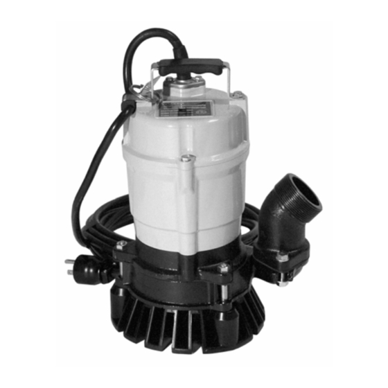
PST2/PSTF2 400 Operation Operation Names of Parts See Graphic: wc_gr001699 wc_gr001699 Description Description Lifting handle Oil plug Mechanical seal Dust seal Lubricant Sleeve Oil housing Impeller Coupling Stirrer nut Volute Strainer Gasket Oil lifter Cable assembly wc_tx000111gb.fm... -
Page 10: Prior To Operation
(32–104°F) which can lead to failure, current leakage or shock. Do not use in the vicinity of explosive or flammable materials. Use only in fully assembled state. Note: Consult your local dealer or Wacker Neuson representative before using with any liquids other than those indicated in this document. - Page 11 PST2/PSTF2 400 Operation Preparing for installation Before installing the pump at a work site, you will need to have the following tools and instruments ready: • Insulation resistance tester (megohmmeter) • AC voltmeter • AC ammeter (clamp-on type) • Bolt and nut tighteners •...
- Page 12 2.3.4 If used in a permanent installation where the pump is not readily accessible after installation, please contact Wacker Neuson for a duplicate nameplate to be installed at the wellhead or on the control box so that it will be readily visible.
-
Page 13: Installing The Float (If Equipped)
PST2/PSTF2 400 Operation Installing the Float (if equipped) See graphic: wc_gr005664 wc_gr005664 2.4.1 Set the length of the float lead wire to the dimension indicated below. Failure to set the correct lead wire length will lead to improper operation of the pump. Pump model Length “L”... - Page 14 Operation PST2/PSTF2 400 Notes: wc_tx000111gb.fm...
-
Page 15: Electrical Wiring
PST2/PSTF2 400 Operation Electrical Wiring Performing electrical wiring Electrical wiring should be performed by a qualified person in accord with all applicable regulations. Failure to observe this precaution not only risks breaking the law but is extremely dangerous. WARNING Incorrect wiring can lead to current leakage, electrical shock or fire. Always make sure the pump is equipped with the specified overload protectors and fuses or breakers, so as to prevent electrical shock from a current leak or pump malfunction. - Page 16 Operation PST2/PSTF2 400 See Graphic: wc_gr000242 Cable Assembly If it is necessary to extend the cable assembly, use a core size equal to or larger than the original. This is necessary not only to avoid a performance drop, but to prevent cable overheating which can result in CAUTION fire, electrical leakage or electrical shock.
-
Page 17: Electrical Circuit Diagrams
PST2/PSTF2 400 Operation Electrical Circuit Diagrams See Graphic: wc_gr006190 PST2 400 PSTF2 400 R(Br) W (L) wc_gr006190 If connected to a circuit protected by a fuse, use a time-delay fuse with this pump. CAUTION Ref. Description Ref. Description Capacitor Frame grounding Main coil Ground Auxiliary coil... - Page 18 Operation PST2/PSTF2 400 Wire Colors Black Violet Orange Green White Purple Blue Yellow Shield Pink Brown Light Blue Clear Green/Yellow Gray wc_tx000111gb.fm...
-
Page 19: Operation
PST2/PSTF2 400 Operation Operation Before starting 2.7.1 Make sure once again that the product is of the correct voltage and frequency rating. NOTICE: Using the product at other than rated voltage and frequency will not only lower its performance but may damage the product. Note: Confirm the rated voltage and frequency on the model nameplate. - Page 20 Operation PST2/PSTF2 400 COUNTERMEASURE: If the supply voltage is outside the tolerance, possible causes are the power supply capacity or an inadequate extension cable. Look again at the wiring diagram and make sure the conditions are proper. In case of very excessive vibration, unusual noise or odor, turn off the power immediately and consult your nearest dealer or Wacker representative.
- Page 21 PST2/PSTF2 400 Operation Operating water level Do not operate the pump below the C.W.L. (Continuous running Water Level) indicated below. Failure to observe this condition may result in damage to the pump, current leakage or electrical shock. CAUTION See Graphic: wc_gr001222 C.W.L wc_gr001222 NPT 45-degree hose coupling is standard for the US market.
-
Page 22: Automatic Operation (Pstf2 400 Only)
If the pump operates abnormally (i.e. exhibits an unusually large amount of vibration, noise, or odor), disconnect the power supply immediately and contact your Wacker Neuson dealer. Do not operate CAUTION the pump in this condition, otherwise there is a risk of current leakage, electrical shock, or fire. -
Page 23: Residue Plate
PST2/PSTF2 400 Operation Residue Plate See graphic: wc_gr001144 The residue plate kit contains the residue plate, washers, and bolts. Reuse nuts from pump assembly. 2.9.1 Remove the strainer (3) by loosening the three nuts (1) and removing the three bolts (2). Keep nuts for reuse. 2.9.2 Position washers (4) and attach the residue plate (5) with new bolts (6) included with kit. -
Page 24: Maintenance
(2) See Lubricant Inspection and Lubricant Change in this section. (3) Specialized know-how is required for inspecting and replacing the mechanical seal. Consult with your nearest dealer or Wacker Neuson representative. (4) Consult with your nearest dealer or Wacker Neuson representative regarding overhauls. wc_tx000112_orig_gb.fm... -
Page 25: Maintenance And Inspection
Note: Touch-up paint is not supplied. Note that some kinds of damage or looseness may require that the unit be disassembled for repairs. Please consult your nearest dealer or Wacker Neuson representative. Storage When the pump is out of use for an extended period, wash it and dry it thoroughly, then store it indoors. - Page 26 Maintenance PST2/PSTF2 400 See Graphic: wc_gr000245 Ref. Description Ref. Description Oil inlet Oil plug Gasket Allen wrench Pump Model Lubricant Capacity PST2 400 160 ml (5.4 fl. oz.) PSTF2 400 Replacement Parts The table lists the parts that need to be replaced periodically. Replace these using the recommended frequency as a guideline.
-
Page 27: Disassembly And Reassembly
The procedure for disassembly and reassembly is shown here to the extent necessary for impeller replacement. A specialized environment and facilities are necessary for work on the mechanical seal and the motor parts. Contact your nearest dealer or Wacker Neuson representative in the event such repairs are necessary. wc_tx000112_orig_gb.fm... -
Page 28: Disassembly
Maintenance PST2/PSTF2 400 Disassembly See Graphic: wc_gr000411 Note: For assembly or disassembly, place the pump on its side. Note: It is not necessary to drain the oil for disassembly and inspect ion of the impeller (w) or volute (aa). However, drain oil if further disassembly and testing is required. -
Page 29: Impeller Inspection
PST2/PSTF2 400 Maintenance Impeller Inspection See Graphic: wc_gr000411 3.5.1 Visually inspect impeller (w) for corrosion, wear or damage. Worn impellers compromise peak performance. 3.5.2 Visually inspect impeller key and rotor shaft keyway for signs of uneven wear. 3.5.3 Visually inspect volute (aa) casting for cracks, wear and damage. Look for signs of wear on volute cutwaters and surfaces facing impeller. -
Page 30: Impeller Reassembly
Maintenance PST2/PSTF2 400 Impeller Reassembly See Graphic: wc_gr000411 Note: If, upon inspection and testing, a pump component requires replacement, use only original manufacturer’s replacement parts. 3.6.1 Turn pump on its side. 3.6.2 Pre-assemble the dust seal (u) and sleeve (v). Slide the two pieces (u &... -
Page 31: Troubleshooting
Before ordering repairs, carefully read through this manual, then repeat the inspection. If the problem remains, contact your nearest dealer or Wacker Neuson representative. Always turn off the power before inspecting the pump. Failure to observe this precaution can result in serious accident. -
Page 32: Technical Data
Technical Data PST2/PSTF2 400 Technical Data Standard Specifications Applicable Liquids, Rain Water, Ground Water, Sand-Carrying Water Consistency and Temperature 0–40°C (32–104°F) Pump Impeller Semi-Vortex Type Shaft Seal Double Mechanical Seal Bearing Shielded Ball Bearing Motor Specification Dry Submersible Induction Motor (2-Pole) Insulation Class E... -
Page 33: Operating Specifications
PST2/PSTF2 400 Technical Data Operating Specifications Part No. PST2 400 / PSTF2 400 Pump Electric Power V/Ph/Hz 110/1/60 Rated Current Starting Method Capacitor-Run Bore mm (in.) 50 (2) Output kW (Hp) 0.40 (0.50) Maximum Head m (ft.) 12 (39) Maximum Capacity L/min 200 (53) (GPM) -
Page 34: Dimensions
Technical Data PST2/PSTF2 400 Dimensions 4.3.1 340*** (13.5) (7.3) (9.8) (7.3) (8.1) (10.1) (3.5) 385**** 2" (12.9) (15.2) 40** 45° (1.6) (13.0) (6.4) 120*** (4.8) PSTF2 400 PST2 400 wc_gr006191 *Start range ** Stop range *** Minimum **** Maximum wc_td000034gb.fm... - Page 48 Wacker Neuson Production Americas LLC, N92W15000 Anthony Ave., Menomonee Falls, WI. 53051 Tel.: (262) 255-0500 Fax: (262) 255-0550 Tel.: (800) 770-0957 Wacker Neuson Limited - Room 1701–03 & 1717–20, 17/F. Tower 1, Grand Century Place, 193 Prince Edward Road West, Mongkok, Kowloon, Hongkong. Tel: (852) 3605 5360, Fax: (852) 2758 0032...
Need help?
Do you have a question about the PST2-400 and is the answer not in the manual?
Questions and answers