Sign In
Upload
Manuals
Brands
Thermal Dynamics Manuals
Welding System
ULTRA-CUT 100
Thermal Dynamics ULTRA-CUT 100 Cutting Manuals
Manuals and User Guides for Thermal Dynamics ULTRA-CUT 100 Cutting. We have
1
Thermal Dynamics ULTRA-CUT 100 Cutting manual available for free PDF download: Operating Manual
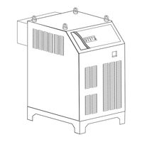
Thermal Dynamics ULTRA-CUT 100 Operating Manual (144 pages)
Plasma cutting system
Brand:
Thermal Dynamics
| Category:
Welding System
| Size: 15 MB
Table of Contents
Table of Contents
5
General Information
9
1.01 Notes, Cautions and Warnings
9
1.02 Important Safety Precautions
9
1.03 Publications
11
1.04 Declaration of Conformity
13
1.05 Statement of Warranty
14
Section 2: Specifications
15
General Description of the System
15
Plasma Power Supply
15
Remote Arc Starter
15
Gas Control Module
15
Precision Plasma Cutting Torch
15
Specifications & Electrical Requirements
16
System Component Layout
16
Power Supply Dimensions
17
Power Supply Rear Panel Features
18
Gas Requirements
19
Gas Applications
19
XTTM-300 Torch Specifications
20
Section 3: Installation
23
Installation Requirements
23
Cooling System Requirements
23
System Layout
24
Cables & Leads Identification
25
Lift the Power Supply
26
E -1. Set Switches on the Command - Control Module (Type 1 Module)
27
E -2. Set Switches on the Command - Control Module (Type 2 Module)
29
Remove the Connections Cover
31
Connect Work Cable and Pilot and Negative Leads
32
Check / Adjust Input Voltage Configuration
33
Connect Input Power and System Ground Cables
34
Ground Connections
35
Connect Coolant Leads
37
Connect Control Cables for CNC, Remote Arc Starter, and GCM
38
Gas Control Module Installation
41
Fiber Optic Cable Installation
42
Gas Control Module: Control, Input, and Output Connections
45
Install Remote Arc Starter
46
Original & XTL Torch Valve Installation
55
Connecting Torch
56
Install Consumable Torch Parts
58
Complete the Installation
62
Section 4: Operation
65
Power Supply Control Panel
65
Start-Up Sequence
66
Gas Control Module Operation
67
Gas Control Module: Controls & Indicators
68
Sequence of Operation
71
Nitride Build-Up
72
Gas Selection
74
Power Supply Status Codes
75
Remote Arc Starter: Service Chart
78
Remote Arc Starter: Spark Gap Adjustment
79
Section 5: Maintenance
81
External Coolant Filter Cleaning Procedure
81
Internal Coolant Filter Cleaning Procedure
82
Coolant Replacement Procedure
82
Section 6: Replacement Assemblies & Parts
83
System Layout
84
Leads and Cables
85
Optional Gas Supply Leads
90
Power Supply External Replacement Parts
91
Power Supply Replacement Parts - Right Side
92
Power Supply Replacement Parts - Right Side
94
Power Supply Replacement Parts - Front Panel
95
Power Supply Replacement Parts - Right Side
97
Power Supply Replacement Parts - Rear Panel
98
Power Supply Replacement Parts - Right Side
99
Power Supply Replacement Parts
100
Power Supply Replacement Parts - Right Side
101
Power Supply Replacement Parts
102
Power Supply Replacement Parts - Right Side
103
Power Supply Replacement Parts - Right Side
104
Gas Control Module (GCM-2010) Replacement Parts
105
Remote Arc Starter (RAS-1000) Replacement Parts
107
Command & Control Module Type 1- Replacement Parts
109
Command & Control Module Type 2 - Replacement Parts
110
Torch Valve Assembly Replacement Parts
111
XTL Torch Valve Assembly External Replacement Parts
112
XTL Torch Valve Assembly Internal Replacement Parts
113
Section 7: Torch Maintenance
115
Consumable Removal
115
O-Ring Lubrication
116
Parts Wear
116
Torch Consumables Installation
117
Coolant Leak Trouble-Shooting
119
APPENDIX 1: Remote Arc Starter Schematic
121
APPENDIX 2: Gas Control and Torch Valve Schematic
122
APPENDIX 3: Gas Control Module
124
APPENDIX 4: Gas Control Module PCB Layout
125
APPENDIX 5: Gas Control Display Module PCB Layout
126
APPENDIX 6: CCM CPU PCB Layout
127
APPENDIX 7: CCM Input-Output PCB Layout
128
APPENDIX 8: CNC - Control Module PCB Connections
129
CNC Functions
130
CNC Input / Output Descriptions
131
Simplified CNC Circuit
132
APPENDIX 9: Schematic, 230-460V Power Supply
134
APPENDIX 10: Schematic, CCC 400V Power Supply
136
APPENDIX 11: Schematic, CE 400V Power Supply
138
APPENDIX 12: Schematic, CSA 600V Power Supply
140
APPENDIX 13: Publication History
142
Global Customer Service Contact Information
143
Advertisement
Advertisement
Related Products
Thermal Dynamics 1-4200-6
Thermal Dynamics 1-4730-6
Thermal Dynamics 101 CUTMASTER
Thermal Dynamics 152 CUTMASTER
Thermal Dynamics 200 ULTRA-CUT
Thermal Dynamics 35C
Thermal Dynamics 35C DRAG-GUN PLUS
Thermal Dynamics 38 Cutmaster
Thermal Dynamics 42 CUTMASTER
Thermal Dynamics 51 CUTMASTER
Thermal Dynamics Categories
Welding System
Power Supply
Cutter
Controller
Welding Accessories
More Thermal Dynamics Manuals
Login
Sign In
OR
Sign in with Facebook
Sign in with Google
Upload manual
Upload from disk
Upload from URL