Table of Contents
Advertisement
Manual Assembly Instructions
- Separate this sheet from the rest of the manual.
- Locate and remove 'Page 1' of this manual. Follow the directions on 'Page 1'.
- Locate the set of tabs for this manual.
- Locate the torch information section, which will become section 8 of this manual.
- Find the sheets saying 'Insert Section ___ tab here. Discard this sheet'. Insert the appropriate
tabs and discard the 'Insert Section ___ tab here. ' sheet.
- At Section 8, insert the torch information section.
-Insert the assembled manual sections and tabs into the 3-ring binder.
- Keep this manual with the power supply for installation, operation, maintenance, and replacement
parts information.
OPTIONAL:
Copy Section 8 (torch operational data) for operator convenience. This section includes data that
will be needed repeatedly for system operation, depending on the metal to be cut and the gases in
use.
- Discard this sheet.
NOTE:
Power supply schematics are provided separately. The system operator may want to keep them
with this book or in a separate location.
Manual No. 0-4805-AR
Advertisement
Table of Contents

Related Manuals for Thermal Dynamics VICTOR 200 AUTO-CUT


Summary of Contents for Thermal Dynamics VICTOR 200 AUTO-CUT
- Page 1 Manual Assembly Instructions - Separate this sheet from the rest of the manual. - Locate and remove 'Page 1' of this manual. Follow the directions on 'Page 1'. - Locate the set of tabs for this manual. - Locate the torch information section, which will become section 8 of this manual. - Find the sheets saying 'Insert Section ___ tab here.
- Page 2 This page intentionally blank...
- Page 3 Cut out one strip and use as spine label in binder. Discard extras. Use next page as front cover insert in binder. Pg 1 Manual No. 0-4805...
- Page 4 This page intentionally blank...
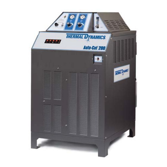
- Page 5 ® AUTO-CUT PLASMA CUTTING SYSTEM Operating Manual Rev. AR Date: January 8, 2013 Manual # 0-4805 Operating Features:...
- Page 6 This page intentionally blank...
- Page 7 ® AUTO-CUT PLASMA CUTTING SYSTEM Operating Manual Rev. AR Date: January 8, 2013 Manual # 0-4805 Operating Features:...
- Page 8 YOU ARE IN GOOD COMPANY! The Brand of Choice for Contractors and Fabricators Worldwide. Thermal Dynamics is a Global Brand of manual and automation Plasma Cutting Products for Thermadyne Industries Inc. We distinguish ourselves from our competition through market- leading, dependable products that have stood the test of time.
- Page 9 WARNINGS Read and understand this entire Manual and your employer's safety practices before installing, operating, or servicing the equipment. While the information contained in this Manual represents the Manufacturer's best judge- ment, the Manufacturer assumes no liability for its use. Plasma Cutting Power Supply, Auto-Cut ®...
- Page 10 This page intentionally blank...
- Page 11 INSERT TABLE OF CONTENTS TAB HERE. DISCARD THIS SHEET.
- Page 12 This page intentionally blank...
-
Page 13: Table Of Contents
TABLE OF CONTENTS SECTION 1: GENERAL INFORMATION ....................1-1 1.01 Notes, Cautions and Warnings ..............1-1 1.02 Important Safety Precautions ............... 1-1 1.03 Publications ....................1-2 1.04 Note, Attention et Avertissement ..............1-3 1.05 Precautions De Securite Importantes ............1-3 1.06 Documents De Reference ................ - Page 14 TABLE OF CONTENTS SECTION 5: MAINTENANCE ....................5-1 5.01 General Maintenance ..................5-1 5.02 Coolant Filter Cleaning Procedure ..............5-1 5.03 Water Filter Cleaning Procedure ..............5-2 5.04 Coolant Replacement Procedure ..............5-3 5.05 Arc Starter Service ..................5-4 5.06 Arc Starter Spark Gap Adjustment ............... 5-5 SECTION 6: REPLACEMENT ASSEMBLIES &...
- Page 15 TABLE OF CONTENTS Appendix 1: Control Cable Pinouts .................... A-1 Appendix 2: Control Cable Pinouts .................... A-2 Appendix 3: Command-Control PC Board Layout (A) ..............A-3 Appendix 4: Command-Control PC Board Layout (B) ..............A-4 Appendix 5: CNC - Control Module Board PCB Connections ............. A-6 CNC functions.
- Page 16 TABLE OF CONTENTS...
- Page 17 Insert Section 1 tab here. Discard this sheet...
-
Page 19: General Information
AUTO-CUT 200 SECTION 1: • Use an air-supplied respirator if ventilation is not adequate to remove all fumes and gases. GENERAL INFORMATION • The kinds of fumes and gases from the plasma arc depend on the kind of metal being used, coatings on the metal, and the different processes. -
Page 20: Publications
AUTO-CUT 200 • Provide a fire watch when working in an area where fire hazards 1.03 Publications may exist. Refer to the following standards or their latest revisions for more infor- • Hydrogen gas may be formed and trapped under aluminum mation: workpieces when they are cut underwater or while using a water table. -
Page 21: Note, Attention Et Avertissement
AUTO-CUT 200 THAT HAVE HELD HAZARDOUS SUBSTANCES, obtainable from the American Welding Society, 550 N.W. LeJeune Rd, FUMÉE et GAZ Miami, FL 33126 15. ANSI Standard Z88.2, PRACTICE FOR RESPIRATORY PRO- La fumée et les gaz produits par le procédé de jet de plasma peuvent TECTION, obtainable from American National Standards présenter des risques et des dangers de santé. - Page 22 AUTO-CUT 200 • Utilisez la nuance de lentille qui est suggèrée dans le recommenda- • Montez et maintenez le matériel conformément au Code électrique tion qui suivent ANSI/ASC Z49.1: national des Etats-Unis. (Voir la page 5, article 9.) Nuance Minimum Nuance Suggerée •...
-
Page 23: Documents De Reference
AUTO-CUT 200 1.06 Documents De Reference 14. Norme AWSF4.1 de l’Association Américaine de Soudage, RECOMMANDATIONS DE PRATIQUES SURES POUR LA Consultez les normes suivantes ou les révisions les plus récentes ayant PRÉPARATION À LA COUPE ET AU SOUDAGE DE CONTENEURS été... -
Page 24: Declaration Of Conformity
Rigorous testing is incorporated into the manufacturing process to ensure the manufac- tured product meets or exceeds all design specifications. Thermal Dynamics has been manufacturing products for more than 30 years, and will continue to achieve excellence in our area of manufacture. -
Page 25: Statement Of Warranty
90 Days Warranty repairs or replacement claims under this limited warranty must be submitted by an authorized Thermal Dynamics® repair facility within thirty (30) days of the repair. No transportation costs of any kind will be paid under this warranty. Transportation charges to send products to an authorized warranty repair facility shall be the responsibility of the customer. - Page 26 Australia Terms of Warranty – 2012 Effective 1st January 2012, all warranties against defects (also known as a manufacturer’s warranty) supplied with goods or services must comply with the new Australian consumer law regulations (2010). This Warranty Statement should be read in conjunction with the Warranty Schedule contained in the operating instructions of the product.
- Page 27 Insert Section 2 tab here. Discard this sheet.
-
Page 29: Section 2: Specifications
SECTION 2: SPECIFICATIONS 2.01 General Description Of The System A typical Auto-Cut ® 200 plasma cutting system includes: • One Power Supply • Arc Starter / Gas Control Module (Mounted on Power Supply) • General Purpose Plasma Cutting Torch with Connecting Leads •... -
Page 30: Power Supply Specifications & Electrical Requirements
2.06 Power Supply Specifications & Electrical Requirements Auto-Cut 200 Power Supply Specifications Max OCV (U 380 vdc Max Output Current 200 Amps Output Voltage 160 vdc Duty Cycle Rating 100% @ 200A @ 160V (32 kW) Operating range 14°F to 122°F (-10°C to + 50°C) Power Factor 0.70 @ 100 ADC Output Cooling... -
Page 31: Power Supply Dimensions
2.07 Power Supply Dimensions 27 inch 680 mm 41.25 inch 1050 mm 48.75 inch 1238 mm 33 inch 840 mm 27.5 inch 700 mm 37.75 inch 397 lb / 180 kg 960 mm Art # A-04822 Manual No. 0-4805 Auto-Cut 200 SPECIFICATIONS... -
Page 32: Power Supply Rear Panel Features
2.08 Power Supply Rear Panel Features Gas Control Connector Torch Leads Port Arc Starter Input Power Connector Pilot (Pos) Terminals Terminal Torch (Neg) AC Power Lamp Terminal Gas Entry Ports Circuit Breaker Panel Ground Terminals Gas Control Connector Terminal Cover CNC Connection Work Cable Terminal Arc Starter Connector... -
Page 33: Gas Requirements
2.09 Gas Requirements The customer will provide all gases and pressure regulators. Gases must be of high quality. Pressure regulators shall be equipped with stainless-steel diaphragms and installed as close as possible to the Gas Console. Auto-Cut 200 BASIC Power Supply: Gas Pressures, Flows, and Quality Requirements Quality Minimum Pressure Flow... - Page 34 2.11 XT -301 Torch Specifications A. Torch Dimensions Art # A-05856 End Cap 19.00" 2.25" 482.68 mm 57.15 mm Mounting Tube 2.0" 15.50" 50.8 mm 393.78 mm Torch Body 6.30" 160.10 mm 2.39" 60.81 mm 3.54" 89.87 mm 2.74" 69.55 mm 1.57"...
- Page 35 B. Torch Leads Lengths Gas Lead Assemblies Length Feet Meters 3.05 15.2 22.8 30.4 C. Torch Parts (Generic Parts Shown) Art # A-04741 Plasma Gas Shield Gas Distributor Distributor Shield Cap Electrode Shield Cup Cartridge D. Parts - In - Place (PIP) The torch is designed for use with a power supply which senses coolant return flow to confirm that torch parts are in place.
-
Page 36: Xttm-301 Torch Specifications
E. Type Cooling Combination of gas stream through torch and liquid cooling. F. XT -301 Torch Data (with Auto-Cut 200 Power Supply) -301 Torch Ratings (when used with Auto-Cut 200 Power Supply) Ambient 104° F Temperature 40° C Duty Cycle 100% @ 100 Amps Maximum Current 200 Amps... - Page 37 Insert Sec. 3 tab here. Discard this sheet. Manual No. 0-4805 Auto-Cut 200 SPECIFICATIONS...
-
Page 39: Section 3: Installation
Cooling System Requirements Coolant must be added to the system on installation. The amount required varies with torch leads length. Thermal Dynamics recommends the use of its coolants 7-3580 and 7-3581 (for low temperatures). Coolant Capabilities Cat. Number and Mixture... -
Page 40: Cables And Leads Identification
3.02 Cables and Leads Identification Refer to section 3.05 for ground connections and ground cables. Arc Starter / Maximum Length 100’ / 30.5 m Gas Control Module (GCM-1000) Ground Pilot Return Cable Torch Lead Set, Shielded Control - Coolant Supply w/ Negative Negative Cable - Coolant Return... -
Page 41: Cables & Leads Identification
3.03 Cables & Leads Identification #8 AWG Cable Pilot Return, Power Supply to Arc Starter #1 AWG Cable Negative Lead, Power Supply to Arc Starter Green Green Coolant Leads, Power Supply to Arc Starter Control Cable, Power Supply to Arc Starter Ground Cable Green / Yellow #10 AWG Ground Cable,... -
Page 42: Position The Power Supply
3.04 Position the Power Supply WARNINGS Do not touch live electrical parts. Disconnect input power conductors from de-energized supply line before moving unit. FALLING EQUIPMENT can cause serious personal injury and equipment damage. Use all four lifting eyes when using lifting straps to lift the power supply. Use a forklift, crane, or hoist to lift the unit off the shipping pallet as shown. -
Page 43: Primary Power Connections
3.05 Primary Power Connections The primary power cable must be supplied by the end user and connected to the power supply. Refer to local and national electrical codes for suggested cable and fuse sizes. Remove the connections cover on the rear of the Power Supply. Use caution when removing the panel; there is a ground wire connected to the inside of the panel. - Page 44 Check / Adjust Input Voltage Configuration (208-230 / 460 V Only) 1. The power supply includes a voltage configuration board which must be positioned to match the primary input voltage. Remove the power supply left side panel and locate the voltage configuration board. The input voltage configuration is shown at the top of the board.
- Page 45 Connect Input Power and System Ground Cables 1. Carefully cut back the outer sheath on the primary input power cable to expose the individual wires. Cut back the insulation on the individual wires. Route the cable upward through the connections cover support panel on the rear panel of the power supply.
- Page 46 Ultra-Cut Star Ground on Cutting Table Auto-Cut O2 Remote Arc Power Supply Starter (RAS-1000) Gas Control Module Gas Control Module Primary location Torch Alternate location Device Cutting Machine / Gantry #4 AWG #4 AWG Ground Ground Cutting Table Ground Cable Note: The gas control module can be mounted on top of the power supply.
- Page 47 Auto-Cut Basic System Without RAS Cutting Machine / Gantry Torch Auto-Cut GCM-1000 Device Power Supply Gas Control Module Cutting Table #4 AWG Ground (Factory Installed) Ground Cable 1/0 Work Cable Earth Ground 1/0 Ground Cable (F1) ‘Star’ Art # A-08254 0 - 10 ft (0 - 3 m) Ideal Ground 20 ft (6 m) Maximum...
-
Page 48: Ground Connections
For Thermal Dynamics components (except Arc Starter and Gas Control Module) it is recommended to use a minimum of 10 AWG (European 6 mm ) wire or flat copper braid with cross section equal to or greater than 10 AWG connected to the cutting table frame. - Page 49 C. Creating An Earth Ground 1. To create a solid, low resistance, earth ground, drive a 1/2 in (12 mm) or greater diameter copper clad ground rod at least 6 - 8 ft (1.8 - 2.4 m) into the earth so that the rod contacts moist soil over most of its length. Depending on location, a greater depth may be required to obtain a low resistance ground (see NOTE).
-
Page 50: Connect Work Cable
D. Routing Of Torch Leads 1. To minimize RF interference, position torch leads as far as possible from any CNC components, drive motors, control cables, or primary power lines. If cables have to pass over torch leads, do so at an angle. Do not run the plasma control or other control cables in parallel with the torch leads in power tracts. -
Page 51: Connect Gas Supply Lines
3.08 Connect Gas Supply Lines 1. Connect the gas supply lines to the appropriate input ports as shown. Plasma Gas - In Water - In Shield Gas - In RETURN SUPPLY RETURN SUPPLY Art # A-04844 Manual No. 0-4805 Auto-Cut 200 3-13 INSTALLATION... -
Page 52: Connect Cnc Cable
3.09 Connect CNC Cable 1. Connect one end of the CNC cable to the power supply receptacle marked ‘CNC’. 2. Connect the other end of the cable to the CNC device. 3. The CNC cable shield must be attached to ground. To CNC RETURN SUPPLY... -
Page 53: Set Switches For Type 2 Command-Control Module
3.10 Set Switches for Type 2 Command-Control Module Remove the power supply right side. Set switches on the CCM (Command-Control Module) per the illustrations. Switch settings and connection details are provided in the Appendix. CAUTION Printed circuit boards in the Command - Control Module are static - sensitive. Discharge any built-up static charges in your body or surroundings before touching the printed circuit boards. - Page 54 CAUTION Printed circuit boards in the Command - Control Module are static - sensitive. Discharge any built-up static charges in your body or surroundings before touching the printed circuit boards. SW11 No external connection cover SW12 SW13 SW-6: OK-to-Move: Contact closure, 120VAC @ 1A (Factory default setting) or DC Volts (16-18vdc@ up to 100 ma.) SW-11: Analog Current Control.
-
Page 55: Height Control Connections
3.11 Height Control Connections The terminal strip has Arc Volts (-) connection to power supply negative output TORCH terminal, Arc Volts (+) connection to power supply positive output WORK terminal. These are for a height control that requires connection to the full non-divided arc voltage. Also available on the terminal strip are 120VAC (120,0) and 24 VAC (24, 0). -
Page 56: Connect Torch Leads To The Gas Control Module / Arc Starter
3.12 Connect Torch Leads to the Gas Control Module / Arc Starter 1. Remove the top cover from the Gas Control Module / Arc Starter. 2. Pass the torch leads and coolant leads through the torch leads port on the back of the module. Ensure that the leads outer jacket slides into the port. - Page 57 Coolant Return Coolant Supply Connection (Tagged Red) Connection (Tagged Green) Plasma Gas Connection Shield Gas Connection Torch Leads Art # A-04832 5. Fold the end of the leads outer jacket back over the connection ring inside the module. Slide the leads clamp over the jacket and fasten the clamp and jacket to the connection ring.
- Page 58 Clamp Inner Shield Connection for OLDER LEADS ONLY Art # A-04935_AB Manual No. 0-4805 Auto-Cut 200 3-20 INSTALLATION...
-
Page 59: Torch Head Installation And Connection
3.13 Torch Head Installation and Connection Install the Torch as follows: 1. Install the torch mounting block on the cutting table (gantry). Fasten the block in place. 2. Leave the end cap in place on the torch leads. Remove and discard the protective end caps from the Mounting Tube. -
Page 60: Install Consumable Torch Parts
5. Slide the positioning tube down to the torch head. Hold the torch head stationary. Rotate the positioning tube onto the torch head. Pull the leads back as needed to ensure a proper fit through the Mounting Tube. Do not let the torch leads twist. CAUTION Ensure that the leads do not twist within the mounting tube. - Page 61 1: Stack Parts 2: Press Cartridge onto Stacked Parts Electrode Plasma Gas Distributor O-Ring on Tip No Gaps Between Parts Shield Gas Cartridge Covers Distributor O-Ring on Torch Tip Shield Cap 4: Check Shield Cap Protrusion 3: Thread Shield Cup onto Cartridge Shield Cup Shield Cap Shield Cap Protrudes...
- Page 62 5. Use the removal tool to hold the cartridge assembly, while turning the shield cup onto the cartridge assembly. When this group is fully assembled, the shield should protrude from the front of the shield cup 0.063" to 0.083" (1.6 - 2.1 mm). Without this protrusion the shield cup is not properly tightened onto the cartridge assembly.
- Page 63 7. Confirm proper parts assembly as shown. Torch Head Torch Head O-Ring 0.063 - 0.083" (1.6 - 2.1 mm) Protrusion Art # A-07202 8. Slide the ohmic clip over the shield cup if using ohmic torch height sensing. NOTE Ohmic height sensing is not recommended with water shield. Water on the plate interferes electrically with the ohmic sensing circuit.
- Page 64 Complete the Installation 1. Fill the coolant tank to the level shown, with Thermal Dynamics coolant. The coolant level is visible through the translucent coolant tank. The amount of coolant required varies with torch leads length. 2. Replace the cap on the tank.
- Page 65 NOTE Depending on the length of the torch leads, the system may require more coolant after turning the system ON for the first time. a. Place the ON/OFF Switch to ON. The power supply will start to circulate coolant throughout the system. b.
- Page 66 This Page Intentionally Blank...
- Page 67 Insert Sec. 4 tab here. Discard this sheet.
-
Page 69: Section 4: Operation
SECTION 4: OPERATION 4.01 Power Supply Indicators Status Indicator AC Indicator Gas Indicator Temp Indicator DC Indicator Art # A-04813 AC Power Lamp Indicates AC power is being supplied to the system when the ON/OFF switch is in ON position. When switch is first set to ON, the lamp will blink, indicating gas purge at power on. -
Page 70: Control Console Features
4.02 Control Console Features Art # A-06802 CU T OU T Shield Gas Plasma Gas Pressure Gauge Pressure Gauge Run / Set Selector PLASMA SHIELD Amperage Selector 1000 SHIELD H 2 O MIST O MIST Shield Shield Gas Pressure Plasma Gas Pressure Water Mist (Shield) Flow Meter Selector Control Knob... -
Page 71: Operating Set-Up
4.03 Operating Set-up Follow this set-up procedure each time the system is operated: WARNING Disconnect primary power at the source before assembling or disassembling power supply, torch parts, torch and leads assemblies or adding coolant. A. Coolant Level Inspection Check the coolant level in the coolant tank at the rear of the unit. If the tank is below 3/4 full, add coolant. B. - Page 72 H. Plasma Gas Purge Move the Power Supply ON/OFF switch to the ON position. An automatic gas purge will remove any condensation that may have accumulated in the torch and leads while the system was shut down. After the purge is complete, if the RUN/SET switch is in SET position, gases will flow.
-
Page 73: Cut Quality
4.04 Cut Quality Cut quality requirements differ depending on application. For instance, nitride build-up and bevel angle may be major factors when the surface will be welded after cutting. Dross-free cutting is important when finish cut quality is desired to avoid a secondary cleaning operation. Cut quality will vary on different materials and thicknesses. Kerf Width Cut Surface Bevel Angle... - Page 74 Direction of Cut The plasma gas stream swirls as it leaves the torch to maintain a smooth column of gas. This swirl effect results in one side of a cut being more square than the other. Viewed along the direction of travel, the right side of the cut is more square than the left.
-
Page 75: System Operation
4.05 System Operation This section contains operating information which is specific to the power supply. WARNINGS Frequently review the safety precautions in Section 1. Disconnect primary power at the source before assembling or disassembling power supply, torch parts, or torch and leads assemblies, or adding coolant. It is not enough to simply move the ON/OFF switch on the unit to OFF position when cutting operations have been completed. - Page 76 4. Place RUN/SET switch to SET mode. a. Gases flow to set pressures. 5. Place RUN/SET switch to RUN mode. a. Gas flow stops. 6. Protect eyes and start torch. a. Gas pre-flows starts. 7. After gas pre-flow: a. Power supply enabled. DC lamp turns ON. 8.
- Page 77 Operational Suggestions 1. Wait five minutes before setting the ON/OFF switch to OFF after operation. This allows the cooling fan to run to dissipate operating heat from the power supply. 2. For maximum parts life, do not operate the pilot arc any longer than necessary. 3.
- Page 78 Note These codes are for systems with Firmware versions 2.4 or later. If your system’s Firmware is a prior version, contact your distributor for updates. Fault Code Key Error Code Error Remedy / Comments External E-Stop Activated Check and correct. Plasma Enable Switch OFF Pilot Ignition Failure Pilot does not start >...
- Page 79 Warning does not stop cut. Stop cut, shut off input (during cut) power, add coolant to tank. Contact Thermal Dynamics. CCM Analog Voltage Error CCM Analog to Digital Coverter Contact Thermal Dynamics. Contact Thermal Dynamics. Coolant Flow Circuit Error Contact Thermal Dynamics. CCM Data Memory Error Manual No.
- Page 81 Insert sec 5 tab here. discard this sheet.
-
Page 83: Section 5: Maintenance
SECTION 5: MAINTENANCE 5.01 General Maintenance Perform the following checks periodically to ensure proper system performance. Power Supply Maintenance Schedule Daily Check coolant level; add coolant as needed. Check gas hose connections and pressures. Check cooling fan; clean as needed. Monthly Check cooling fan and radiator;... -
Page 84: Water Filter Cleaning Procedure
5.03 Water Filter Cleaning Procedure NOTE This procedure is only required in installations using water as a shield. Clean the filter as follows: 1. Disconnect system from main input power. 2. Unscrew and remove the filter bowl by hand. Be sure to keep the gasket. 3. -
Page 85: Coolant Replacement Procedure
5.04 Coolant Replacement Procedure Replace coolant as follows: 1. Disconnect the system from main input power. At the bottom of the coolant tank, disconnect the coolant line fitting and collect coolant in a disposable container. 2. Connect the system to main input power and turn it on to allow the pump to empty the tank,. The pump will run approximately for 20 seconds before the flow switch causes an interlock. -
Page 86: Arc Starter Service
5.05 Arc Starter Service Arc Starter Service Chart Symptom Cause Check Remedy Flush system, Coolant has become conductive Use conductivity meter replace coolant. Pilot return wire not connected Visual inspection Connect Wire. Spark gap set too close Check with feeler gauge Set to 0.063"... -
Page 87: Arc Starter Spark Gap Adjustment
5.06 Arc Starter Spark Gap Adjustment 1. Shut off input power. Remove the top console cover. 2. Adjust the spark gap as shown. Re-install the top cover. 0.063" ± 0.002" 1.6 ± 0.05 mm Art # A-04835 Manual No. 0-4805 Auto-Cut 200 MAINTENANCE... - Page 88 This page is blank intentionally. Manual No. 0-4805 Auto-Cut 200 MAINTENANCE...
- Page 89 Insert Sec 6 tab here. discard this sheet Manual No. 0-4805 Auto-Cut 200 MAINTENANCE...
-
Page 91: Section 6: Replacement Assemblies & Parts
SECTION 6: REPLACEMENT ASSEMBLIES & PARTS 6.01 Replacement Power Supply Complete Unit / Component Catalog Numbers Catalog Number Auto-Cut 200 Power Supply, 208/230V 3-9112-1 Auto-Cut 200 Power Supply, 460V 3-9112-2 Auto-Cut 200 Power Supply, 400V 3-9112-3 Auto-Cut 200 Power Supply, 400V (CE) 3-9112-4 OPTIONAL EQUIPMENT:... -
Page 92: Leads And Cables
6.02 Leads and Cables Refer to section 3.05 for ground connections and ground cables. Arc Starter / Gas Control Module (GCM-1000) G: Torch Lead Set, Shielded Ground Pilot Return Cable - Coolant Supply w/ Negative Control - Coolant Return Negative Cable - Pilot Return Auto-Cut... -
Page 93: Recommended Gas Supply Hose
#8 AWG Cable Pilot Return, Power Supply to Arc Starter #1 AWG Cable Negative Lead, Power Supply to Arc Starter Green Green Coolant Leads, Power Supply to Arc Starter Control Cable, Power Supply to Arc Starter Ground Cable Green / Yellow #10 AWG Ground Cable, Green / Yellow 1/0 (50 mm ) Arc Starter... -
Page 94: Power Supply External Replacement Parts
6.04 Power Supply External Replacement Parts Item # Description Catalog # Power Supply Front Panel Power Supply Rear Panel Power Supply Top Panel 9-0445G/9-0445B Power Supply Right Side 9-0442G/9-0442B Power Supply Left Side 9-0443G/9-0443B Louver Panel Power Supply Connections Cover Lifting Eye 9-9373 Art # A-06888_AB... -
Page 95: Power Supply Replacement Parts - Right Side
6.05 Power Supply Replacement Parts - Right Side Item # Description Ref. Des. Catalog # Heat Exchanger Fan FAN1 9-9338 Radiator 9-9339 Art # A-08308 Manual No. 0-4805 Auto-Cut 200 Parts List... -
Page 96: Power Supply Replacement Parts - Right Side
6.06 Power Supply Replacement Parts - Right Side Item # Description Ref. Des. Catalog # Output Filter PC PCB8 9-9341 Sensor HCT2 9-9368 Magnetic Contactor, pilot 9-9343 Resistor 9-9340 Resistor Capacitor Art # A-08309 Manual No. 0-4805 Auto-Cut 200 Parts List... -
Page 97: Power Supply Replacement Parts - Right Side
6.07 Power Supply Replacement Parts - Right Side Item # Description Ref. Des. Catalog # Chopper Module 9-9389 Sensor HCT1 9-9342 Chopper Module HCT1 Art # A-08311 Manual No. 0-4805 Auto-Cut 200 Parts List... -
Page 98: Power Supply Replacement Parts - Front Panel
6.08 Power Supply Replacement Parts - Front Panel Item # Description Ref. Des. Catalog # Main Power Switch (‘Circuit Protector’) 9-9344 for 230-400-460 VAC units Art # A-08312 Manual No. 0-4805 Auto-Cut 200 Parts List... - Page 99 6.09 Power Supply Replacement Parts - Front Panel Item # Description Ref. Des. Catalog # PC Board PCB3 9-9365 PC Board 230/460VAC PCB4 9-9370 PC Board 600VAC PCB4 9-9492 Display PC Board PCB6 9-9347 PCB3 PCB4 PCB6 Art # A-08313 Manual No.
-
Page 100: Power Supply Replacement Parts - Right Side
6.10 Power Supply Replacement Parts - Right Side Item # Description Ref. Des. Catalog # PCBoard 230-400-460VAC PCB1 9-9362 PCBoard 600VAC PCB1 9-9491 Magnetic Contactor MC1,MC3 9-9364 Art # A-08314 Manual No. 0-4805 Auto-Cut 200 6-10 Parts List... -
Page 101: Power Supply Replacement Parts - Rear Panel
6.11 Power Supply Replacement Parts - Rear Panel Item # Description Breaker Rating Cicuit Rating Ref. Des. Catalog # Circuit Breaker (RAS) 125V, 2.5 A 120VAC @ 1A 9-9348 Circuit Breaker (’TDC’) 125V, 3.15A 24VAC @ 1A 9-9349 Circuit Breaker (AGC) 125V, 10A 24VAC @ 5A 9-9350... -
Page 102: Power Supply Replacement Parts - Right Side
6.12 Power Supply Replacement Parts - Right Side Item # Description Ref. Des. Catalog # Resistor 9-9363 Rectifier (Diode) 9-9345 Transformer 9-9355 for 230/460 VAC units Diode 9-9486 Terminal Strip Art # A-08310 Manual No. 0-4805 Auto-Cut 200 6-12 Parts List... -
Page 103: Power Supply Replacement Parts
6.13 Power Supply Replacement Parts Item # Description Catalog # Inverter Module 208/230V 9-9360D Inverter Module 400V CE and 400V Non CE 9-9482D Inverter Module 600V 9-9485D Art # A-04786_AB Manual No. 0-4805 Auto-Cut 200 6-13 Parts List... -
Page 104: Power Supply Replacement Parts - Right Side
6.14 Power Supply Replacement Parts - Right Side Item # Description Ref. Des. Catalog # Sensor (Thermistor) TH1 9-9361 Art # A-04787 Manual No. 0-4805 Auto-Cut 200 6-14 Parts List... -
Page 105: Power Supply Replacement Parts
6.15 Power Supply Replacement Parts Item # Description Ref. Des. Catalog # Relay PC Board PCB7 9-9366 24 VDC Power Supply Internal Control PC Board PCB5 9-9346 Art # A-08315 Manual No. 0-4805 Auto-Cut 200 6-15 Parts List... -
Page 106: Power Supply Replacement Parts - Right Side
6.16 Power Supply Replacement Parts - Right Side Item # Description Ref. Des. Catalog # Sensor (Level Switch) LSW1 9-9354 Motor 9-9381 Pump/Check Valve/Bypass Valve Assembly 9-9380 Bypass Valve (part of assembly) Pump (part of assembly) Sensor (Flow Indicator) 9-9359 Illustration is for Reference ONLY Art # A-08236 Manual No. -
Page 107: Command & Control Module Type 2 - Replacement Parts
6.17 Command & Control Module Type 2 - Replacement Parts Item # Description Catalog # Assembly, CCM (Auto-Cut) 9-9418 Plate, CCM Face 9-9419 Panel, CCM Mount Not Available Harness, CCM I/O Board 9-9421 NOTE This page covers parts for Command & Control module without an external connections cover. See previous page for Command &... -
Page 108: Arc Starter & Gas Control Module (Gcm-1000) Replacement Parts
6.18 Arc Starter & Gas Control Module (GCM-1000) Replacement Parts Item # Description Catalog # GCM-1000, Gas Box/Arc Starter 9-4997 Base 9-4979 Front Panel 9-4980 Lid (not shown) 9-4981 Gas Bulkhead 9-4982 Bulkhead 9-4983 Solenoid Mount 9-4984 Lid Bracket 9-4985 Bracket, Flotometer H 9-4987 Bulkhead... - Page 109 Art # A-04852_AC Right Side Left Side Manual No. 0-4805 Auto-Cut 200 6-19 Parts List...
- Page 110 This Page Intentionally Blank Manual No. 0-4805 Auto-Cut 200 6-20 Parts List...
- Page 111 Insert Sec. 7 tab here. discard this sheet. Manual No. 0-4805 Auto-Cut 200 6-21 Parts List...
-
Page 113: Section 7: Torch Maintenance
SECTION 7: TORCH MAINTENANCE 7.01 Consumable Removal 1. Use the removal tool to hold the Shield Cup & Cartridge Assembly stationary. Turn the Shield Cup to re- move it from the Cartridge Assembly Cartridge Tool Assembled Cartridge Art # A-04344_AB Shield Cup 2. -
Page 114: O-Ring Lubrication
Cat. No. 9-3025 Art # A-04066_AC CAUTION Use only Thermal Dynamics No. 9-4893 O-Ring Lubricant (Christo Lube MCG-129) with this torch part. Use of other lubricants may cause irreparable damage to the torch. 7.03 Parts Wear Replace the Gas Distributor if it is charred or cracked. -
Page 115: Torch Consumables Installation
7.04 Torch Consumables Installation 1. Install the consumables as follows: WARNINGS Do not install consumables into the Cartridge while the Cartridge is attached to the Torch Head. Keep foreign materials out of the consumables and Cartridge. Handle all parts carefully to avoid damage, which may affect torch performance. - Page 116 1: Stack Parts 2: Press Cartridge onto Stacked Parts Electrode Plasma Gas Distributor O-Ring on Tip No Gaps Between Parts Shield Gas Cartridge Covers Distributor O-Ring on Torch Tip Shield Cap 4: Check Shield Cap Protrusion 3: Thread Shield Cup onto Cartridge Shield Cup Shield Cap Shield Cap Protrudes...
- Page 117 2, Remove the Removal Tool from the Cartridge and install the assembled Cartridge onto the Torch Head. CAUTION The cartridge assembly must cover the O-Ring on the torch head. Do not force the cartridge if it will not tighten fully. Remove the cartridge assembly and gently clean the threads on the torch head with a wire brush.
-
Page 118: Coolant Leak Troubleshooting
E. Coolant Leak Trouble-Shooting Never operate the system if coolant leaks from torch. A steady drip indicates that torch parts are damaged or installed improperly. Operating the system in this condition can damage the torch head. Refer to the following chart for guidance on coolant leakage from the torch head. - Page 119 Insert sec. 8 tab here. discard this sheet. Manual 0-4805 Auto-Cut 200 TORCH MAINTENANCE...
-
Page 121: Appendix 1: Control Cable Pinouts
APPENDIX 1: CONTROL CABLE PINOUTS Power Supply J55 to Gas Control Console J56 4 Ground 7 Ground 8 Ground 6 Pot Wiper 5 + 10 vdc 14 E-Stop 15 E-Stop 11 Gas On 10 Gas On 17 24 VAC Ret 16 24VAC 24 VAC Ret 33 Ground... -
Page 122: Appendix 2: Control Cable Pinouts
APPENDIX 2: CONTROL CABLE PINOUTS Power Supply J59 to Arc Starter / Gas Control Console J58 Art # A-04849 2: Ground 1 - Jumpered to 4 7 - 120 VAC 4 - Jumpered to 1 9: 120 VAC RET POWER SUPPLY J59 ARC STARTER / GAS CONTROL MODULE J58 2: Ground 7 - 120 VAC... -
Page 123: Appendix 3: Command-Control Pc Board Layout (A
APPENDIX 3: COMMAND-CONTROL PC BOARD LAYOUT (A) Note: Switch Settings May Vary. POST OK TO AUTO PILOT FLOW FLOW FUNC CONT MOVE/D CPU/COMMUNICATIONS Switches POST OK TO AUTO PILOT FLOW FLOW FUNC CONT MOVE/D C 2004 TDC 19X2169 REV +5.0V TEMP SENSE TPAD1... -
Page 124: Appendix 4: Command-Control Pc Board Layout (B
APPENDIX 4: COMMAND-CONTROL PC BOARD LAYOUT (B) TP11 TP12 SW11 J5 J5 J8 J8 J6 J6 J7 J7 J4 J4 PILOT V PILOT V R224 R224 L2 L2 R2 R2 TP12 TP12 J1 J1 R225 R225 CC POT CC POT U1 U1 R4 R4 H6 H6... - Page 125 This page is blank intentionally. Manual 0-4805 Auto-Cut 200 APPENDIX...
-
Page 126: Appendix 5: Cnc - Control Module Board Pcb Connections
APPENDIX 5: CNC - CONTROL MODULE BOARD PCB CONNECTIONS These points are jumpered together at the factory. TB1-1 E-Stop (Com) Remove the jumper to use existing E-Stop circuits. TB1-2 E-Stop TB1-3 TB1-4 Stop Latched TB1-5 Start / Stop Ret TB1-6 Start / Stop or Start Latched (NO) TB1-7 Divided Arc Voltage (-) -
Page 127: Cnc Functions
CNC functions. CNC I/O circuits provide at least 1000V galvanic isolation from the plasma power supply. While the CNC circuits are isolated from the power supply, many of the signal returns on J15 and TB1 & 2 are common to each other. J15 pins 1, 4, 5 & 10 and TB1-1, 5, 7, 9, and TB2-1 & 3 are all common. J15 pin 12 and TB2-10 are also connected to the others when SW6 (OK to Move select) is set for voltage. -
Page 128: Cnc Input / Output Descriptions
CNC Input / Output Descriptions E-Stop input— Requires closed connection rated for 35ma. @ 20VDC for unit to operate. Factory installed jumper between TB1-1&2 must be removing when connecting user supplied E-Stop circuit. Start/Stop input—Switch (momentary or sustained) rating 35ma. @ 20 VDC Start / Stop circuit configurations. -
Page 129: Simplified Cnc Circuit
Simplified CNC Circuit. CCM Module SUSTAINED START / STOP ALL SW OFF for 50:1 (default) TB1-5 Active LOW Logic Input START / STOP E-STOP Ret (-) SW12-1 ON = 16.7:1 (SC-11) E-STOP input (+) SW12-2 ON = 30:1 Active LOW Logic Input TB1-6 STOP (NC) SW12-3 ON = 40:1... -
Page 130: Cnc Connections
CNC Connections Cutting Machine CNC Cable Power Supply ..Source, 16 VDC, 10 ma. START/STOP ... Divided Arc V (-) ..Divided Arc V (+) ..Arc V (-) through 100K *** ..Arc V (+) through 100K *** Remote Analog Current Control (-) .. - Page 131 This Page Intentionally Blank Manual 0-4805 Auto-Cut 200 A-11 APPENDIX...
-
Page 132: Appendix 6: Arc Starter / Gas Control Module Schematic
APPENDIX 6: ARC STARTER / GAS CONTROL MODULE SCHEMATIC POWER SUPPLY POWER SUPPLY (4) (4) (5) (5) +10VDC +10VDC (6) (6) (8) (8) (8) (8) (9) (9) POT WIPER POT WIPER (10) (10) (11) (11) (9) (9) GAS ON GAS ON GAS ON GAS ON (12) - Page 133 Date: Date: Date: Date: Date: Information Proprietary to THERMAL DYNAMICS CORPORATION. Information Proprietary to THERMAL DYNAMICS CORPORATION. Information Proprietary to THERMAL DYNAMICS CORPORATION. Information Proprietary to THERMAL DYNAMICS CORPORATION. Information Proprietary to THERMAL DYNAMICS CORPORATION. Information Proprietary to THERMAL DYNAMICS CORPORATION.
- Page 134 APPENDIX 7: POWER SUPPLY SCHEMATIC, 230- 460V, CHOPPER PILOT 100A INVERTER MODULE # 1 (top) N (-) N (-) CN1-230V CN1-230V INRUSH INRUSH MC1-A MC1-A MC1-B MC1-B MC1-C MC1-C P (+) P (+) CN4 - PCB12 CN4 - PCB12 CN2-460V CN2-460V MC3-A MC3-A...
- Page 135 603-298-5711 ECO-B646 GAC 10/31/07 Date: Date: Date: Information Proprietary to THERMAL DYNAMICS CORPORATION. Information Proprietary to THERMAL DYNAMICS CORPORATION. Information Proprietary to THERMAL DYNAMICS CORPORATION. Tuesday, October 03, 2006 Tuesday, October 03, 2006 Tuesday, October 03, 2006 Not For Release, Reproduction, or Distribution without Written Consent.
-
Page 136: Appendix 7: Power Supply Schematic, 230-460V, Chopper Pilot Cont
APPENDIX 7: POWER SUPPLY SCHEMATIC, 230-460V, CHOPPER PILOT CONT. PCB 5 WK-5602 (partial) INTERFACE PCB LED1 LED1 INPUT CONTACTORs LEVEL LEVEL CN12 CN12 CN13 CN13 CN14 CN14 PILOT CONTACTOR MC1 AUX MC1 AUX MC3 AUX MC3 AUX LSW1-1 LSW1-1 COOLANT TEMP (ON COOLANT RETURN) SW_LIQUID_LEVEL_NC... - Page 137 603-298-5711 ECO-B646 GAC 10/31/07 Date: Date: Date: Information Proprietary to THERMAL DYNAMICS CORPORATION. Information Proprietary to THERMAL DYNAMICS CORPORATION. Information Proprietary to THERMAL DYNAMICS CORPORATION. Tuesday, October 03, 2006 Tuesday, October 03, 2006 Tuesday, October 03, 2006 Not For Release, Reproduction, or Distribution without Written Consent.
- Page 138 APPENDIX 8: POWER SUPPLY SCHEMATIC, 230- 460V, RESISTOR PILOT 100A INVERTER MODULE # 1 (top) N (-) N (-) CN1-230V CN1-230V INRUSH INRUSH MC1-A MC1-A MC1-B MC1-B MC1-C MC1-C P (+) P (+) CN4 - PCB12 CN4 - PCB12 CN2-460V CN2-460V MC3-A MC3-A...
- Page 139 603-298-5711 ECO-B646 GAC 10/31/07 Date: Date: Date: Information Proprietary to THERMAL DYNAMICS CORPORATION. Information Proprietary to THERMAL DYNAMICS CORPORATION. Information Proprietary to THERMAL DYNAMICS CORPORATION. Tuesday, October 03, 2006 Tuesday, October 03, 2006 Tuesday, October 03, 2006 Not For Release, Reproduction, or Distribution without Written Consent.
-
Page 140: Appendix 8: Power Supply Schematic, 230-460V, Resistor Pilot Cont
APPENDIX 8: POWER SUPPLY SCHEMATIC, 230-460V, RESISTOR PILOT CONT. PCB 5 WK-5602 (partial) INTERFACE PCB LED1 LED1 INPUT CONTACTORs LEVEL LEVEL CN12 CN12 CN13 CN13 CN14 CN14 PILOT CONTACTOR MC1 AUX MC1 AUX MC3 AUX MC3 AUX LSW1-1 LSW1-1 COOLANT TEMP (ON COOLANT RETURN) SW_LIQUID_LEVEL_NC... - Page 141 603-298-5711 ECO-B646 GAC 10/31/07 Date: Date: Date: Information Proprietary to THERMAL DYNAMICS CORPORATION. Information Proprietary to THERMAL DYNAMICS CORPORATION. Information Proprietary to THERMAL DYNAMICS CORPORATION. Tuesday, October 03, 2006 Tuesday, October 03, 2006 Tuesday, October 03, 2006 Not For Release, Reproduction, or Distribution without Written Consent.
-
Page 142: Appendix 9: Power Supply Schematic, Ccc 400V, Chopper Pilot
APPENDIX 9: POWER SUPPLY SCHEMATIC, CCC 400V, CHOPPER PILOT 100A INVERTER MODULE # 1 (top) N (-) N (-) CN1- not used CN1- not used INRUSH INRUSH MC1-A MC1-A MC1-B MC1-B MC1-C MC1-C P (+) P (+) CN4 - PCB12 CN4 - PCB12 CN2 400V CN2 400V... - Page 143 603-298-5711 ECO-B646 GAC 10/31/07 Date: Date: Date: Information Proprietary to THERMAL DYNAMICS CORPORATION. Information Proprietary to THERMAL DYNAMICS CORPORATION. Information Proprietary to THERMAL DYNAMICS CORPORATION. Tuesday, October 03, 2006 Tuesday, October 03, 2006 Tuesday, October 03, 2006 Not For Release, Reproduction, or Distribution without Written Consent.
-
Page 144: Appendix 9: Power Supply Schematic, Ccc 400V, Chopper Pilot Cont
APPENDIX 9: POWER SUPPLY SCHEMATIC, CCC 400V, CHOPPER PILOT CONT. PCB 5 WK-5602 (partial) INTERFACE PCB LED1 LED1 INPUT CONTACTORs LEVEL LEVEL CN12 CN12 CN13 CN13 CN14 CN14 PILOT CONTACTOR MC1 AUX MC1 AUX MC3 AUX MC3 AUX LSW1-1 LSW1-1 COOLANT TEMP (ON COOLANT RETURN) - Page 145 603-298-5711 ECO-B646 GAC 10/31/07 Date: Date: Date: Information Proprietary to THERMAL DYNAMICS CORPORATION. Information Proprietary to THERMAL DYNAMICS CORPORATION. Information Proprietary to THERMAL DYNAMICS CORPORATION. Tuesday, October 03, 2006 Tuesday, October 03, 2006 Tuesday, October 03, 2006 Not For Release, Reproduction, or Distribution without Written Consent.
- Page 146 APPENDIX 10: POWER SUPPLY SCHEMATIC, CE 400V, CHOPPER PILOT 100A INVERTER MODULE # 1 (top) CN1- not used CN1- not used INRUSH INRUSH N (-) N (-) NFC1 NFC1 MC1-A MC1-A MC1-B MC1-B FILTER FILTER MC1-C MC1-C P (+) P (+) CN4 - PCB12 CN4 - PCB12 CN2 400V...
- Page 147 603-298-5711 ECO-B646 GAC 10/31/07 Date: Date: Date: Information Proprietary to THERMAL DYNAMICS CORPORATION. Information Proprietary to THERMAL DYNAMICS CORPORATION. Information Proprietary to THERMAL DYNAMICS CORPORATION. Tuesday, October 03, 2006 Tuesday, October 03, 2006 Tuesday, October 03, 2006 Not For Release, Reproduction, or Distribution without Written Consent.
-
Page 148: Appendix 10: Power Supply Schematic, Ce 400V, Chopper Pilot Cont
APPENDIX 10: POWER SUPPLY SCHEMATIC, CE 400V, CHOPPER PILOT CONT. PCB 5 WK-5602 (partial) INTERFACE PCB LED1 LED1 INPUT CONTACTORs LEVEL LEVEL CN12 CN12 CN13 CN13 CN14 CN14 PILOT CONTACTOR MC1 AUX MC1 AUX MC3 AUX MC3 AUX LSW1-1 LSW1-1 COOLANT TEMP (ON COOLANT RETURN) - Page 149 603-298-5711 ECO-B646 GAC 10/31/07 Date: Date: Date: Information Proprietary to THERMAL DYNAMICS CORPORATION. Information Proprietary to THERMAL DYNAMICS CORPORATION. Information Proprietary to THERMAL DYNAMICS CORPORATION. Tuesday, October 03, 2006 Tuesday, October 03, 2006 Tuesday, October 03, 2006 Not For Release, Reproduction, or Distribution without Written Consent.
- Page 150 APPENDIX 11: POWER SUPPLY SCHEMATIC, CE 400V, RESISTOR PILOT 100A INVERTER MODULE # 1 (top) CN1- not used CN1- not used INRUSH INRUSH N (-) N (-) NFC1 NFC1 MC1-A MC1-A MC1-B MC1-B FILTER FILTER MC1-C MC1-C P (+) P (+) CN4 - PCB12 CN4 - PCB12 CN2 400V...
- Page 151 603-298-5711 ECO-B646 GAC 10/31/07 Date: Date: Date: Information Proprietary to THERMAL DYNAMICS CORPORATION. Information Proprietary to THERMAL DYNAMICS CORPORATION. Information Proprietary to THERMAL DYNAMICS CORPORATION. Tuesday, October 03, 2006 Tuesday, October 03, 2006 Tuesday, October 03, 2006 Not For Release, Reproduction, or Distribution without Written Consent.
-
Page 152: Appendix 11: Power Supply Schematic, Ce 400V, Resistor Pilot Cont
APPENDIX 11: POWER SUPPLY SCHEMATIC, CE 400V, RESISTOR PILOT CONT. PCB 5 WK-5602 (partial) INTERFACE PCB LED1 LED1 INPUT CONTACTORs LEVEL LEVEL CN12 CN12 CN13 CN13 CN14 CN14 PILOT CONTACTOR MC1 AUX MC1 AUX MC3 AUX MC3 AUX LSW1-1 LSW1-1 COOLANT TEMP (ON COOLANT RETURN) - Page 153 603-298-5711 ECO-B646 GAC 10/31/07 Date: Date: Date: Information Proprietary to THERMAL DYNAMICS CORPORATION. Information Proprietary to THERMAL DYNAMICS CORPORATION. Information Proprietary to THERMAL DYNAMICS CORPORATION. Tuesday, October 03, 2006 Tuesday, October 03, 2006 Tuesday, October 03, 2006 Not For Release, Reproduction, or Distribution without Written Consent.
- Page 154 APPENDIX 12: POWER SUPPLY SCHEMATIC, CSA 600V, CHOPPER PILOT 100A INVERTER MODULE # 1 (top) N (-) N (-) CN1- not used CN1- not used INRUSH INRUSH MC1-A MC1-A MC1-B MC1-B MC1-C MC1-C P (+) P (+) CN4 - PCB12 CN4 - PCB12 CN2 600V CN2 600V...
- Page 155 603-298-5711 ECO-B646 GAC 10/31/07 Date: Date: Date: Information Proprietary to THERMAL DYNAMICS CORPORATION. Information Proprietary to THERMAL DYNAMICS CORPORATION. Information Proprietary to THERMAL DYNAMICS CORPORATION. Tuesday, October 03, 2006 Tuesday, October 03, 2006 Tuesday, October 03, 2006 Not For Release, Reproduction, or Distribution without Written Consent.
-
Page 156: Appendix 12: Power Supply Schematic, Csa 600V, Chopper Pilot Cont
APPENDIX 12: POWER SUPPLY SCHEMATIC, CSA 600V, CHOPPER PILOT CONT. PCB 5 WK-5602 (partial) INTERFACE PCB LED1 LED1 INPUT CONTACTORs LEVEL LEVEL CN12 CN12 CN13 CN13 CN14 CN14 PILOT CONTACTOR MC1 AUX MC1 AUX MC3 AUX MC3 AUX LSW1-1 LSW1-1 COOLANT TEMP (ON COOLANT RETURN) - Page 157 603-298-5711 ECO-B646 GAC 10/31/07 Date: Date: Date: Information Proprietary to THERMAL DYNAMICS CORPORATION. Information Proprietary to THERMAL DYNAMICS CORPORATION. Information Proprietary to THERMAL DYNAMICS CORPORATION. Tuesday, October 03, 2006 Tuesday, October 03, 2006 Tuesday, October 03, 2006 Not For Release, Reproduction, or Distribution without Written Consent.
-
Page 158: Appendix 13: Publication History
APPENDIX 13: PUBLICATION HISTORY Manual No. 0-4805 Cover Date Change(s) Oct 7, 2005 First issue. Oct. 14, 2005 Updated torch data section. Oct. 21, 2005 Added 30-Amp Stainless Steel N2-H20 application. Expanded CCM info. Updated fault code chart on Pg. 4-11. Added 400V units. Added caution against ohmic sensing w/ water shield in torch data section. - Page 159 This Page Intentionally Blank...
- Page 160 THE AMERICAS Denton, TX USA U.S. Customer Care Ph: 1-800-426-1888 (tollfree) Fax: 1-800-535-0557 (tollfree) International Customer Care Ph: 1-940-381-1212 Fax: 1-940-483-8178 Miami, FL USA Sales Office, Latin America Ph: 1-954-727-8371 Fax: 1-954-727-8376 Oakville, Ontario, Canada Canada Customer Care Ph: 1-905-827-4515 Fax: 1-800-588-1714 (tollfree) EUROPE Chorley, United Kingdom...
Need help?
Do you have a question about the VICTOR 200 AUTO-CUT and is the answer not in the manual?
Questions and answers