Sign In
Upload
Manuals
Brands
Omron Manuals
Security Sensors
F3SG-R Series
Omron F3SG-R Series Manuals
Manuals and User Guides for Omron F3SG-R Series. We have
3
Omron F3SG-R Series manuals available for free PDF download: User Manual, Quick Installation Manual
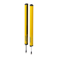
Omron F3SG-R Series User Manual (270 pages)
Safety Light Curtain
Brand:
Omron
| Category:
Safety Equipment
| Size: 9.66 MB
Table of Contents
Terms and Conditions Agreement
5
Safety Precautions
7
Precautions for Safe Use
13
Precautions for Correct Use
14
Visual Aids
15
Table of Contents
17
Chapter1 Overview And Specifications
25
What Is Included
26
System Components
27
Basic Components
28
Model Overview
29
List of Features
30
Model Overview
30
Versions
30
List of Features
31
LED Indicators
33
LED Indicator Status
34
Ratings/Specifications
36
List of Models
40
List of Models/Response Time/Current Consumption/Weight
40
Calculation of Response Time of Cascaded Segments
43
Chapter2 System Operation and Functions
45
Combination of Functions
47
Operating States
49
Machine Run State
49
Machine Stop State
49
Interlock State
49
Lockout State
49
Teach-In Mode
49
Setting State
50
Optical Synchronization
51
Overview
51
Scan Code Selection
52
Overview
52
Factory Default Setting
52
Setting with DIP Switch
52
Setting with Configuration Tool
52
PNP/NPN Selection
53
Overview
53
Factory Default Setting
53
Setting with DIP Switch
53
Setting with Configuration Tool
53
Self-Test
54
Overview
54
Self-Test Details
54
Waveform of Safety Outputs
55
External Test
56
Overview
56
Factory Default Setting
57
Setting with DIP Switch
57
Setting with Configuration Tool
57
Lockout Reset
58
Overview
58
Interlock
59
Over View
59
Factory Default Setting
62
Setting with DIP Switch
62
Setting with Configuration Tool
63
External Device Monitoring (EDM)
64
2-10-1.Overview
64
2-10-2.Factory Default Setting
65
2-10-3.Setting with DIP Switch
65
2-10-4.Setting with Configuration Tool
65
Muting
65
Auxiliary Output
67
2-11-1.Overview
67
2-11-2.Factory Default Setting
68
2-11-3.Setting with DIP Switch
68
2-11-4.Setting with Configuration Tool
69
Muting
71
2-12-1.Standard Muting Mode
73
2-12-2.Exit-Only Muting Mode
83
2-12-3.Position Detection Muting Mode
89
2-12-4.Dynamic Muting
93
2-12-5.Factory Default Setting
94
2-12-6.Setting with DIP Switch
94
2-12-7.Setting with Configuration Tool
94
Override
96
2-13-1.Override at Normal Operation
97
2-13-2.Override Upon Startup
101
2-13-3.Setting with DIP Switch
102
2-13-4.Setting with Configuration Tool
102
Fixed Blanking
103
2-14-1.Overview
103
2-14-2.Factory Default Setting
106
2-14-3.Setting with DIP Switch
106
2-14-4.Setting with Configuration Tool
106
Floating Blanking
107
2-15-1.Overview
107
2-15-2.Factory Default Setting
110
2-15-3.Setting with DIP Switch
110
2-15-4.Setting with Configuration Tool
111
Reduced Resolution
112
2-16-1.Overview
112
2-16-2.Factory Default Setting
113
2-16-3.Setting with DIP Switch
113
2-16-4.Setting with Configuration Tool
113
Warning Zone
115
2-17-1.Overview
115
2-17-2.Factory Default Setting
118
2-17-3.Setting with DIP Switch
118
2-17-4.Setting with Configuration Tool
118
Setting Zone Adjacency Conditions
119
Operating Range Selection
121
2-19-1.Overview
121
2-19-2.Factory Default Setting
121
2-19-3.Setting with DIP Switch
121
2-19-4.Setting by Wiring
122
2-19-5.Setting with Configuration Tool
122
Response Time Adjustment
123
2-20-1.Overview
123
2-20-2.Factory Default Setting
123
2-20-3.Setting with DIP Switch
123
2-20-4.Setting with Configuration Tool
123
Lamp
124
2-21-1.Overview
124
2-21-2.Factory Default Setting
124
2-21-3.Setting with DIP Switch
124
2-21-4.Setting with Configuration Tool
124
Designated Beam Output
127
2-22-1.Overview
127
2-22-2.Factory Default Setting
127
2-22-3.Setting with DIP Switch
128
2-22-4.Setting with Configuration Tool
128
Light Level Monitoring
129
2-23-1.Incident Light Level Information
129
Overview
129
Setting with Configuration Tool
129
2-23-2.Ambient Light Level Information
129
Maintenance Information
130
2-24-1.Overview
130
2-24-2.Error Log
130
2-24-3.Warning Log
130
2-24-4.Power-ON Time
130
2-24-5.Load Switching Frequency
131
2-24-6.Muting Statistics Information
131
Operating Status Monitoring
132
2-25-1.Overview
132
2-25-2.Readout Information
132
Setting Recovery
133
2-26-1.Overview
133
Chapter3 Setting With DIP Switch
135
List of Features Configurable by DIP Switch
136
DIP Switch
137
DIP Switch on Receiver
138
DIP Switch on Emitter
139
Push Switch
139
Setting by Teach-In
140
Setting Fixed Blanking by Teach-In
140
Setting Floating Blanking by Teach-In
143
Chapter4 Wiring/Installation
147
Installation Considerations
149
Detection Zone and Approach
149
Safety Distance
150
Safety Distance Formulas According to ISO 13855/EN ISO 13855
150
Safety Distance Formulas According to ANSI B11.19
153
Distance from Reflective Surfaces
154
F3SG-4R (Type 4 ESPE)
154
F3SG-2R (Type 2 ESPE)
154
Mutual Interference Prevention
155
Cascade Connection
157
Overview
157
Connection Procedure
159
Dimensions
160
Mounted with Standard Fixed Brackets (F39-LGF)
160
F3SG-RA Series
160
Mounting
160
F3SG-RE Series
162
Standard Fixed Bracket
164
Mounted with Standard Adjustable Brackets (F39-LGA)
165
F3SG-RA Series
165
F3SG-RE Series
167
Standard Adjustable Bracket
169
(F39-Lga)
170
F3SG-RA Series
170
F3SG-RE Series
176
Top/Bottom Adjustable Bracket (F39-LGTB)
180
Top/Bottom Adjustable Bracket (F39-LGTB-1)
180
Mounting
181
Mounting Method
181
Number of Brackets Required
181
Mounting Procedure
182
Mounting with Standard Fixed Brackets (F39-LGF)
182
Mounting with Standard Adjustable Brackets (F39-LGA)
183
Mounting with Top/Bottom Adjustable Brackets (F39-LGTB)
187
Beam Alignment Procedure
190
Wiring
191
Wiring Precautions
191
Power Supply Unit
192
Cable Connections(F3SG-RA Series)
193
Single-Ended Cable
193
Double-Ended Cable
194
Cascading Cable
196
Extending Cable Length with Commercially Available Cable
197
Adapter Cable (A)
197
Adapter Cable (B)
199
Reduced Wiring Connector System with Y-Joint Plug/Socket Connector
201
Reduced Wiring Connector System with 4-Joint Plug/Socket Connector
202
Cable Connections(F3SG-RE Series)
205
Recommended Cable
205
Extending Cable Length with Commercially Available Cable
206
Adapter Cable (C)
206
Reduced Wiring Connector System
208
Functional Earth Connection
209
Chapter5 Input/Output Circuit and Applications
211
Input/Output Circuit
213
Entire Circuit Diagram
213
F3SG-RA Series
213
F3SG-RE Series
215
Input Circuit Diagram by Function
217
F3SG-RA Series
217
F3SG-RE Series
217
Wiring Examples(F3SG-RA Series)
218
Standalone F3SG-RA Using PNP Outputs
218
Auto Reset Mode, EDM Disabled and PNP Outputs
218
Manual Reset Mode, EDM Enabled and PNP Outputs
219
Y-Joint Plug/Socket Connector Using PNP Outputs
220
Pre-Reset Mode Using PNP Output
221
Muting Using PNP Outputs
222
Standard Muting Mode/Exit-Only Muting Mode Using PNP Outputs
222
Mode Using PNP Outputs
223
Puts
224
Standard Muting Mode with Four Muting Sensors Using PNP Outputs
225
Standard Muting Mode with F3W-MA
226
Connector)
226
Exit-Only Muting Mode with F3W-MA
227
Connector)
227
Standalone F3SG-RA Using NPN Outputs
228
Auto Reset Mode, EDM Disabled and NPN Outputs
228
Manual Reset Mode, EDM Enabled and NPN Outputs
229
Y-Joint Plug/Socket Connector Using NPN Outputs
230
Pre-Reset Mode Using NPN Output
231
Muting Using NPN Outputs
232
Standard Muting Mode/Exit-Only Muting Mode Using NPN Outputs
232
Puts
233
Standard Muting Mode with Four Muting Sensors Using NPN Outputs
234
Wiring Examples (F3SG-RE Series)
235
Short Mode
235
Long Mode
236
Standalone F3SG-RE with Y-Joint Plug/Socket Connector
237
Connectable Safety Control Units
238
Chapter6 Checklists
239
Pre-Operation Checklists
240
Checklists
240
Installation Condition Check
240
Wiring Check before Power Is Turned on
240
Operation Check While the Machine Is Stopped
241
Checking that Hazardous Parts Stop While the Machine Operates
242
Maintenance Checklists
243
Checklists
243
Inspection at Startup and When Changing Operators
243
Checking that Hazardous Parts Stop While the Machine Operates
244
Items to Inspect Every 6 Months or When Machine Settings Are Changed
244
Chapter7 Appendix
247
Troubleshooting
248
Lockout State
249
Description
249
Troubleshooting
250
Warning
254
Description
254
Troubleshooting
254
Muting Sequence Error Indication
255
Interlock Sequence Error Indication
256
Optional Accessories(Sold Separately)
257
Glossary
265
Revision History
269
Advertisement
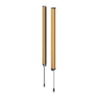
omron F3SG-R Series User Manual (128 pages)
F3SG-4RA-25-02TS Series
Brand:
omron
| Category:
Security Sensors
| Size: 4.1 MB
Table of Contents
Terms and Conditions Agreement
5
Safety Precautions
7
Precautions for Safe Use
11
Precautions for Correct Use
12
Visual Aids
14
Table of Contents
15
Chapter1 Overview And Specifications
21
What Is Included
22
System Components
23
Basic Components
24
List of Features
25
Model Overview
25
LED Indicators
26
LED Indicator Status
27
Ratings/Specifications
28
List of Models
31
List of Models/Response Time/Current Consumption/Weight
31
Calculation of Response Time of Cascaded Segments
32
Chapter2 System Operation and Functions
33
Operating States
34
Machine Run State
34
Machine Stop State
34
Lockout State
34
Optical Synchronization
35
Overview
35
Scan Code Selection
36
Overview
36
Factory Default Setting
36
Setting
36
Self-Test
37
Overview
37
Self-Test Details
37
Waveform of Safety Outputs
38
External Test
39
Overview
39
Factory Default Setting
39
Setting
39
Lockout Reset
40
Overview
40
External Device Monitoring (EDM)
41
Overview
41
Auxiliary Output
42
Overview
42
Factory Default Setting
42
Lamp
43
Overview
43
Light Level Monitoring
44
2-10-1.Incident Light Level Information
44
Overview
44
Setting with Configuration Tool
44
2-10-2.Ambient Light Level Information
44
Maintenance Information
45
2-11-1.Overview
45
2-11-2.Error Log
45
2-11-3.Warning Log
45
2-11-4.Power-ON Time
45
2-11-5.Load Switching Frequency
45
Operating Status Monitoring
46
2-12-1.Overview
46
2-12-2.Readout Information
46
Chapter3 Setting With Rotary Switch and End Cap
47
List of Features Configurable by Rotary Switch
48
Rotary Switch
49
List of Features Configurable by End Cap
50
End Cap
51
Chapter4 Wiring/Installation
53
Installation Considerations
55
Detection Zone and Approach
55
Safety Distance
56
Safety Distance Formulas According to ISO 13855/EN ISO 13855
56
Safety Distance Formulas According to ANSI B11.19
59
Distance from Reflective Surfaces
60
Type 4 ESPE
60
Mutual Interference Prevention
61
Cascade Connection
62
Overview
62
Connection Procedure
64
Dimensions
65
Mounted with Free-Location Brackets (F39-LGRA)
65
Backside Mounting
65
Side Mounting
66
Free-Location Bracket / Intermediate Bracket (F39-LGRA)
67
Free-Location Bracket / Intermediate Bracket
67
Mounted with Top/Bottom Brackets (F39-LGRTB) and Intermediate Bracket (F39-LGRA)
68
Backside Mounting
68
Lgra)
68
Side Mounting
69
Top/Bottom Bracket (F39-LGRTB)
70
Backside Mounting
71
Mounted with Top/Bottom Brackets (F39-LGRTB-2) and Intermediate Bracket (F39-LGRA)
71
Side Mounting
72
Top/Bottom Bracket (F39-LGRTB-2)
73
Mounted with Top/Bottom Brackets (F39-LGRTB-3) and Intermediate Bracket (F39-LGRA)
74
Backside Mounting
74
Side Mounting
75
Top/Bottom Bracket (F39-LGRTB-3)
76
Mounted with Top/Bottom Brackets (F39-LGRTB-□) and Accessories
77
Connected with Cascading Cable (F39-JGR2WTS)
77
Connected with Bluetooth ® Communication Unit (F39-BT)
78
Connected with Bluetooth® Communication Unit
78
Bluetooth® Communication Unit (F39-BTLP)
79
Mounting
80
Mounting Method
80
Number of Brackets Required
80
Mounting Procedure
81
Mounting with Free-Location Brackets (F39-LGRA)
81
Lgra)
84
Intermediate Bracket (F39-LGRA)
84
Beam Alignment Procedure
88
Wiring
89
Wiring Precautions
89
Power Supply Unit
90
Cable Connections
91
Single-Ended Cable (Oil-Resistant Cable)
91
Single-Ended Cable
92
Double-Ended Cable
93
Cascading Cable
95
Reduced Wiring Connector System
96
Extending Cable Length with Commercially Available Cable
97
Functional Earth Connection
98
Chapter5 Input/Output Circuit and Applications
99
Input/Output Circuit
100
Entire Circuit Diagram
100
Input Circuit Diagram by Function
101
Wiring Examples
102
EDM Used and External Test in 24V Active Not Used
102
EDM Not Used and External Test in 0V Active Used
103
F3SG-R with Reduced Wiring Connector
104
Connectable Safety Control Units
105
Chapter6 Checklists
107
Pre-Operation Checklists
108
Checklists
108
Installation Condition Check
108
Wiring Check before Power Is Turned on
108
Operation Check While the Machine Is Stopped
109
Checking that Hazardous Parts Stop While the Machine Operates
109
Maintenance Checklists
110
Checklists
110
Inspection at Startup and When Changing Operators
110
Checking that Hazardous Parts Stop While the Machine Operates
111
Items to Inspect Every 6 Months or When Machine Settings Are Changed
111
Chapter7 Appendix
113
Troubleshooting
114
Lockout State
114
Description
114
Troubleshooting
115
Warning
118
Description
118
Troubleshooting
118
Troubles Other than in Lockout State
119
Optional Accessories(Sold Separately)
120
Glossary
126
Revision History
127
Omron F3SG-R Series Quick Installation Manual (10 pages)
Safety Light Curtain
Brand:
Omron
| Category:
Security Sensors
| Size: 1.23 MB
Table of Contents
1 What Is Included
2
Table of Contents
2
2 System Components
3
3 F3SG-RE Setup Procedure Example
3
4 Wiring Examples
4
Long Mode
4
Short Mode
4
5 Mounting and Beam Alignment
5
Mounting with Standard Fixed Brackets (F39-LGF)
5
Mounting with Standard Adjustable Brackets (F39-LGA)
7
6 Operation Check
10
Suitability for Use/Contact Information
10
Advertisement
Advertisement
Related Products
Omron F3SG-*RR Series
Omron F3SG-4RA****-25-02TS series
Omron F3SG-4SRA0880-14-F
Omron F3SG-4SRA0280-25-F
Omron F3SG-4SRB0640-25
Omron F3SG-4SRB0960-25
Omron F3SG-4SRA1520-25
Omron F3SG-4SRB1840-25
Omron F3SG-4SRA1920-25
Omron F3SG-4SRB0720-45
Omron Categories
Blood Pressure Monitor
Controller
Accessories
Switch
Inverter
More Omron Manuals
Login
Sign In
OR
Sign in with Facebook
Sign in with Google
Upload manual
Upload from disk
Upload from URL