Greenheck ERCH-20 Installation, Operation And Maintenance Manual
Energy recovery ventilator
with heating and cooling
Hide thumbs
Also See for ERCH-20:
- Installation, operation and maintenance manual (56 pages) ,
- Installation, operation and maintenance manual (44 pages)
Table of Contents
Advertisement
Installation, Operation and
Job Title:
Engineer:
Contractor:
Elevation: (ft)
Date:
P.O. Box 410
CAPS 4.18.1634
Maintenance Manuals
TEEN CENTER - LOS ALAMOS
ARSED ENGINEERING
COMFORT SYSTEMS
7,320
09/10/15
MECHANICAL REPRESENTATIVES INC
8322 WASHINGTON PLACE NE
ALBUQUERQUE , NM 87113-1669
US
Phone: (505)821-2563
Fax:
Email Address:
Schofield, WI 54476
G:\JOBS\TEEN CENTER - LOS ALAMOS.gfcj
(505)821-7546
adania@mechrep.com
(715) 359-6171
FAX (715) 355-2399
www.greenheck.com
Page 1 of 2
Advertisement
Chapters
Table of Contents
Troubleshooting

Related Manuals for Greenheck ERCH-20


Summary of Contents for Greenheck ERCH-20
- Page 1 MECHANICAL REPRESENTATIVES INC 8322 WASHINGTON PLACE NE ALBUQUERQUE , NM 87113-1669 Phone: (505)821-2563 Fax: (505)821-7546 Email Address: adania@mechrep.com P.O. Box 410 Schofield, WI 54476 (715) 359-6171 FAX (715) 355-2399 www.greenheck.com CAPS 4.18.1634 G:\JOBS\TEEN CENTER - LOS ALAMOS.gfcj Page 1 of 2...
- Page 2 TEEN CENTER - LOS ALAMOS Product IOMs Mark Name Model Name ERV-1 ERCH EF-1 ALT. 1 EF-4, EF-2, EF-3 CAPS 4.18.1634 G:\JOBS\TEEN CENTER - LOS ALAMOS.gfcj Page 2 of 2...
-
Page 3: General Safety Information
ERV-1 Document 476054 Model ERCH Energy Recovery Ventilator ® with Heating and Cooling Installation, Operation and Maintenance Manual Please read and save these instructions for future reference. Read carefully before attempting to assemble, install, operate or maintain the product described. Protect yourself and others by observing all safety information. Failure to comply with instructions could result in personal injury and/or property damage! General Safety Information Only qualified personnel should install this system. -
Page 4: Table Of Contents
Table of Contents Start-Up General Safety Information ....1 Warnings ....... . .29 Receiving, Handling and Storage . -
Page 5: Receiving, Handling And Storage
Receiving The unit should be stored at least 3½ in. (89 mm) off the floor on wooden blocks covered with moisture proof Upon receiving the product check to make sure all items paper or polyethylene sheathing. Aisles between parts are accounted for by referencing the bill of lading to and along all walls should be provided to permit air ensure all items were received. -
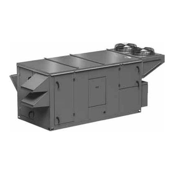
Page 6: Product Overview
353°F. They are pressure Heat Pump Expansion tested with 600 PSIG of dry nitrogen. The most frequent ERCH-20 4, 5, 6, single stage 4, 5, 6, 7 single stage use of steam coils is for retrofitting or modifying existing steam heat systems. - Page 7 Split DX Electric Post-Heaters The unit is equipped with an evaporator coil that The optional post-heater is used as a heat source for will be connected to a separate condensing unit the building and is integrated into the supply airstream. (provided by others).
-
Page 8: Installation Unit Dimensions And Weights
Model Weight Exhaust Outdoor Air Configuration Length Width Height (lbs) Hood Hood Heating Only 76.2 1550 Cooling Coil* 96.2 1825 ERCH-20 54.3 54.2 20.8 17.7 2350 WSHP 108.2 2375 Evap Cooling 1800 Heating Only 84.3 2325 Cooling Coil* 104.3 2725 ERCH-45 64.4... -
Page 9: Curb Outside Dimensions, Recommended Roof Openings And Curb Weights
Length Width Adder per inch Vestibule Heating Only 71.8 49.9 12.3 +6.9 +8.3 28.3 Cooling Coil* 91.8 49.9 +7.7 +9.5 32.8 ERCH-20 43.5 +10.1 42.5 WSHP 103.8 49.9 +8.3 Evap Cooling 28.3 Heating Only 79.9 12.3 +8.0 +9.4 31.8 Cooling Coil* 99.9... -
Page 10: Service Clearances And Access Locations
filter sections are always provided with a service door or panel for proper component access. *Cassette removal only available Model A (in.) B (in.) on housing sizes 20 and 45. ERCH-20 ERCH-45 ERCH-55 ERCH-90 EXHAUST AIR WEATHERHOOD ELECTRICAL BOX... -
Page 11: Belt And Bearing Maintenance
filter sections are always provided with a service door or panel for proper component access. *Cassette removal only available Model A (in.) B (in.) on housing sizes 20 and 45. ERCH-20 ERCH-45 ERCH-55 ERCH-90 EXHAUST AIR WEATHERHOOD ELECTRICAL BOX... - Page 12 filter sections are always provided with a service door or panel for proper component access. *Cassette removal only available Model A (in.) B (in.) on housing sizes 20 and 45. ERCH-20 ERCH-45 ERCH-55 ERCH-90 EXHAUST AIR WEATHERHOOD ACCESS PANEL...
- Page 13 filter sections are always provided with a service door or panel for proper component access. *Cassette removal only available Model A (in.) B (in.) on housing sizes 20 and 45. ERCH-20 ERCH-45 ERCH-55 ERCH-90 EXHAUST AIR WEATHERHOOD ACCESS PANEL...
- Page 14 filter sections are always provided with a service door or panel for proper component access. *Cassette removal only available Model A (in.) B (in.) on housing sizes 20 and 45. ERCH-20 ERCH-45 ERCH-55 ERCH-90 EXHAUST AIR WEATHERHOOD ELECTRICAL BOX...
-
Page 15: Handling
Handling Lifting While this unit was constructed with quality and WARNING dependability in mind, damage still may occur during All factory-provided lifting lugs must be used when handling of the unit for installation. Exercise extreme caution to prevent any damage from occurring to the lifting the units. -
Page 16: Roof Curb Mounting
3. Install Ductwork: Installation of all ducts should Unit Size Heating Only Cooling Coil be done in accordance with SMACNA and AMCA ERCH-20 guidelines. Duct adapter provided to support ducts ERCH-45 prior to setting the unit. ERCH-55 4. Set the Unit: Lift unit to a point directly above the ERCH-90 curb and duct openings. -
Page 17: Rail Mounting/Layout
Rail Mounting / Layout ERCH-20 Recommended Duct Size 1. Rails designed to handle the weight of the unit Intake Duct Size Discharge 9-9 Blower 10-6 Blower should be positioned as shown on the diagram (rails 22 x 26 16 x 16 16 x 16 by others). -
Page 18: Electrical Installation
Electrical Installation 1. Determine the Size of the Main Power Lines The unit’s nameplate states the voltage and the unit’s MCA. The main power lines to the unit should be WARNING sized accordingly. The nameplate is located on the The roof lining contains high voltage wiring. To prevent outside of the unit on the control panel side. -
Page 19: Field-Provided Disconnect
Field-Provided Disconnect Typical Control Center Components with Microprocessor Control If field-installing an additional disconnect switch, it is recommended that there is at least four feet of service room between the switch and system access panels. When providing or replacing fuses in a fusible disconnect, use dual element time delay fuses and size according to the rating plate. -
Page 20: Optional Accessory Wiring Schematics
Optional Accessory Wiring Schematics Unit Interfacing Terminals Remote Panel Heating/Cooling Switches and Night Setback Switch/ The remote panel is available with a number of different Timer alarm lights and switches to control the unit. The remote panel ships loose and requires mounting and wiring in TERMINAL BLOCKS IN UNIT CONTROL CENTER the field. -
Page 21: Piping Installation Optional Gas Piping
Piping Installation 2. Connect the water supply to the bottom connection on the air leaving side and the water return to the Optional Gas Piping top connection on the air entering side. Connecting the supply and/or return in any other manner will Units with indirect gas-fired furnaces require field- result in very poor performance. -
Page 22: Condensate Drain Trap
Tonnage pan with a 1-inch MPT stainless steel drain connection. (in. FPT) Connections It is important that the drain connection be fitted with a ERCH-20 P trap to ensure proper drainage of condensate while ERCH-45 maintaining internal static pressures. ERCH-20 A P trap assembly (kit) is 1.25... -
Page 23: Evaporative Cooler
Optional Evaporative Cooler 3. Check/Adjust Water Level. Check the water level in the sump tank. The water level should be above the CAUTION pump intake and below the overflow. Adjust the float as needed to achieve the proper water level. All solenoids valves and traps must be installed below the roof to protect the supply water line from freezing. -
Page 24: Water Supply Locations
461264 8210G35 Open (19.05 mm) Drain Part numbers subject to change. Water Supply Connection Locations for Evaporative Cooler Water Supply Connection Locations Model ERCH-20 37.5 ERCH-45 45.25 51.5 ERCH-55 ERCH-90 Dimensions from outside of unit (in inches) Ø0.875 Run 1/4 in. line up through 7/8 in. hole here and bring around end of sump to supply connection. -
Page 25: Unit Overview Basic Unit
Unit Overview Optional Component Overview Basic Unit Economizer The unit is pre-wired such that when a call for outside The energy wheel operation can be altered to take air is made (via field-supplied 24 VAC control signal advantage of economizer operation (free cooling). wired to unit control center), the supply fan, exhaust fan, Two modes are available: and energy wheel are energized and optional motorized... -
Page 26: Frost Control
Frost Control Variable Frequency Drives (VFD) Extremely cold outdoor air temperatures can cause Variable frequency drives are used to control the speed moisture condensation and frosting on the energy of the fan as either multi-speed or modulating control. recovery wheel. Frost control is an optional feature that Multi-speed VFDs reference a contact which can be will prevent/control wheel frosting. -
Page 27: Microprocessor Control
Microprocessor Control Hot Gas Reheat Valve The microprocessor controller is specifically designed Units equipped with a reheat coil and programmed to optimize the performance of the use a three-way valve with actuator unit with supplemental to control the supply air discharge heating and cooling. -
Page 28: Outdoor Airflow Monitor
Outdoor Airflow Monitor Smoke Detector A factory-wired, mounted and powered airflow The Hochiki America DH-98 duct monitoring system is provided. The airflow control smoke detector provides early system offers the following functionality: detection of smoke and products of combustion present in air moving •... -
Page 29: Cooling System Overview Packaged Dx
Cooling System Overview Packaged DX Cooling with Digital Scroll Compressor Condenser Airflow Supply Airflow 1. Compressor 9. Sight Glass 2. High Limit Pressure Switch 10. Liquid Line Filter Drier The switch opens when refrigerant pressure 11. Thermostatic Expansion Valve (TXV) increases above the set point in the liquid line and Each unit is equipped with a TXV on each it then requires a manual reset. -
Page 30: Water-Source Heat Pump (Hp)
Water-Source Heat Pump with Standard Scroll Compressor Water Out Water In Supply Airflow 1. Compressor 12. Coaxial Refrigerant-to-Water Heat Exchanger The unit uses one coaxial heat exchanger per 2. High Limit Pressure Switch compressor, essentially a tube inside a tube. 3. -
Page 31: Start-Up
Start-Up Unit SPECIAL TOOLS REQUIRED • Voltage Meter (with wire probes) DANGER • Amperage Meter Electric shock hazard. Can cause injury or death. • Pressure Gauges – (refrigerant) Before attempting to perform any service or • Tachometer maintenance, turn the electrical power to unit to OFF •... -
Page 32: Pre-Start-Up Checklist
Pre Start-Up Every installation requires a comprehensive start-up Rotate the fan wheels and energy recovery wheels to ensure proper operation of the unit. As part of that by hand and ensure no parts are rubbing. process, the following checklist must be completed and Check the fan belt drives for proper alignment and information recorded. - Page 33 Heating System / Electric Heat Pre-Heater L1-L2 Volts L2-L3 Volts L1-L3 Volts Amps Amps Amps Temp. Rise Post-Heater L1-L2 Volts L2-L3 Volts L1-L3 Volts Amps Amps Amps Temp. Rise Cooling System Outdoor Air Temperature Deg F Outdoor Air Relative Humidity % RH Return Air Temperature Deg F...
-
Page 34: Optional Accessories Checklist
Optional Accessories Checklist Refer to the respective sections in this Installation, Operation and Maintenance Manual for detailed information. Refer to wiring diagram in unit control center to determine what electrical accessories were provided. Frost Control Application / Operation Section: Setting Factory Default Frost Control set point 5°F... -
Page 35: Start-Up Components Energy Wheel
Start-Up Components Push the wheel cassette back into the unit and plug in the power connector. Turn the main power supply Energy Wheel back on and then observe the operation of the wheel by opening the wheel access door slightly. Remove filters if The energy wheel is installed in the unit’s airstream with necessary to observe the wheel. -
Page 36: Vibration
Max RPM Max RPM 5. Place belts over sheaves. Do not pry or force belts, as this could result in 10 x 6 1700 ERCH-20 damage to the cords in the belts. 9 x 9 1750 2800 2 in. 6. With the fan off, adjust the belt tension... -
Page 37: Optional Start-Up Components Dirty Filter Switch
Optional Start-Up Components Using the Keypad with Settings and Parameters To use the keypad when working with Set Points, Dirty Filter Switch System and Advanced Settings, Checkout Tests, and To adjust the switch, the unit must be running with Alarms: all of the access doors in place, except for the 1. -
Page 38: Frost Control
Stop Wheel Frost Control 1. Navigate to the Checkout menu and press (enter). Timed Exhaust 2. The energy wheel and cooling should stop. 1. Remove power from unit. 3. Navigate to Connect ERV and press (enter) twice 2. Jumper the frost indicating wheel pressure switch in to run the test. -
Page 39: Outdoor Airflow Monitor
Outdoor Airflow Monitor 8. Measure the supply airflow rate of the unit using an approved test and balance method. For additional information on how to navigate through the airflow controller menus, refer to technical manuals 9. Without making any changes to the system, GF-2200A from GreenTrol®... -
Page 40: Evaporative Cooler
Evaporative Cooler Set the Timer Scale and Settings dials: • t timer setting set to 10 and timer scale set to 1. Check the Installation. The media may have been 1d for 1 day of operation removed during installation, so its orientation should be double •... -
Page 41: Variable Frequency Drives
Most of the set points in the VFDs are Yaskawa factory defaults. However, a 0-10 VDC CONTROL SIGNAL (BY OTHERS) few set points are changed at Greenheck and are shown A1 AC WIRED TO A1 (+) AND AC (COMMON) in the tables. -
Page 42: Variable Frequency Drives
Modulating Control for Fan Speed Proportional Control (0-10 VDC) Setting Setting Parameter Parameter V1000 J1000 V1000 J1000 A1-01 Access Level B1-17 VFD Start-Up Setting B1-17 VFD Start-Up Setting C6-02 Carrier Frequency C6-02 Carrier Frequency D2-02 Ref Lower Limit D2-02 Ref Lower Limit E2-01 Motor Rated FLA Motor... -
Page 43: Routine Maintenance
Annually Routine Maintenance It is recommended that the annual inspection and maintenance occur at the start of the cooling season. DANGER After completing the checklist, follow the unit start- Electric shock hazard. Can cause injury or death. up checklist provided in the manual to ensure the Before attempting to perform any service or refrigeration system operates in the intended matter. -
Page 44: Maintenance Procedures
Maintenance Procedures the belt deflection should be one inch (using moderate thumb pressure at mid-point of the drive). Check belt WARNING tension two times during the first 24 hours of operation and periodically thereafter. REFER TO GENERAL SAFETY INFORMATION Do not operate this unit without the filters and Fan Motors birdscreen installed. -
Page 45: Internal Filter
(inches) Supply Exhaust will grow due to airborne spores and bacteria. Periodic ERCH-20 20 x 20 cleaning is necessary to prevent this buildup from ERCH-45 20 x 25 plugging the drain and causing the drain pan to... -
Page 46: Energy Wheel
Energy Wheel Maintenance Cleaning Maintenance or cleaning of the wheel segments WARNING should be done with the segments removed from the wheel cassette to avoid splashing liquids or Whenever performing maintenance or inspections, cleaning agents inside the cabinet. If the energy wheel always disconnect the power source. -
Page 47: Evaporative Cooling
Evaporative Cooling Maintenance h. Clean all remaining components (i.e. sump, pump, etc.) of any mineral deposits or foreign Regularly scheduled maintenance is the key to peak materials. performance, minimized cost, and extended life of the i. Replace all worn or non-functioning parts. evaporative cooler. -
Page 48: Troubleshooting Unit
Troubleshooting – Unit Symptom Possible Cause Corrective Action Blown fuse or open circuit breaker. Replace fuse or reset circuit breaker and check amps. Defective motor or capacitor. Replace. Blower fails to Motor overloaded. Reset VFD and check amps. operate Check for On/Off switches. Check for correct supply voltage. Electrical. -
Page 49: Refrigeration Circuit
Troubleshooting – Refrigeration Circuit TROUBLESHOOTING NOTE IMPORTANT Do not release refrigerant to the atmosphere! If Before any components are changed on the required service procedures include the adding or refrigeration system, the cause of the failure must be removing of refrigerant, the service technician must identified. - Page 50 Troubleshooting – Refrigeration Circuit Symptom Possible Cause Corrective Action Refrigerant overcharge. Check pressures, charge by subcooling. Condenser fan motor defective. Check fan motor. Compressor starts but Condenser coil inlet obstructed or dirty. Check coil and clearances. Clean coil if necessary. cuts out on Check high side equalized pressures, check thermal expansion high pressure...
- Page 51 Troubleshooting – Refrigeration Circuit Symptom Possible Cause Corrective Action Check for high entering wet bulb temperature, check for Excessive load on evaporator coil. excessive air flow. Compressor is unloaded. Check digital scroll controller signal and solenoid valve. (digital scroll) Check the thermal expansion valve, ensure bulb is insulated. Check superheat.
-
Page 52: Energy Wheel
Troubleshooting – Refrigeration Circuit Symptom Possible Cause Corrective Action Thermostat location or controls malfunction. Check thermostat, check heat anticipator setting. Improper refrigerant charge. Check subcooling, verify superheat. Defective low pressure control. Check high or low pressure switch. Compressor Poor air distribution. Check ductwork for recirculating. -
Page 53: Evaporative Cooling
Troubleshooting – Evaporative Cooling Symptom Possible Cause Corrective Action Check water level in sump pan. Water level should be Water level in sump pan too low. maintained at greater than one inch. Check the pump filter at the inlet. Clean the filter if Pump filter clogged. - Page 54 Troubleshooting – Evaporative Cooling Pad installed backwards. To get the performance from the cooling pads, they must be installed properly. The pads are manufactured with 15/45 degree flute angles. The pads must always be installed with the steeper flute angle sloping down toward the entering air side. Poor performance °...
-
Page 55: Controller Alarms
Troubleshooting - Controller Alarms Troubleshooting - Rotation Sensor The first step in troubleshooting the unit is to check When the unit is first turned on, the LED on the back of the on-board alarm indicators. Several of the electronic the sensor should turn on and stay on with the wheel controls in the unit monitor the system for faults and will running. -
Page 56: Unit Protection Module
High pressure lockout Refer to the following Installation, Operation and Compressor 1 Maintenance Manuals for additional details. All are available at www.greenheck.com Low pressure lockout Compressor 1 • DDC Controller for Energy Recovery High pressure lockout • ERCH Curbs Compressor 2 •... -
Page 57: Venting Connection Locations
Flue Connection Size (diameter in inches) Furnace Size Housing Standard Non-Concentric Concentric (MBH) Size Exhaust Exhaust Intake Exhaust Intake 12.42 24.20 20.05 23.21 ERCH-20 12.42 24.20 20.05 23.21 12.63 24.42 20.25 23.52 12.63 24.42 20.25 23.52 ERCH-45 24.94 24.32 33.87 21.21... -
Page 58: Maintenance Log
_________________________________________________ _________________________________________________ Our Commitment As a result of our commitment to continuous improvement, Greenheck reserves the right to change specifications without notice. Specific Greenheck product warranties are located on greenheck.com within the product area tabs and in the Library under Warranties. - Page 59 EF-1 Document 471558 Model G Direct Drive Model GB Belt Drive ® Downblast Centrifugal Roof Exhaust Installation, Operation and Maintenance Manual Please read and save these instructions for future reference. Read carefully before attempting to assemble, install, operate or maintain the product described. Protect yourself and others by observing all safety information.
- Page 60 If damaged, immediately contact your Greenheck Representative. Any physical damage to the unit after acceptance is not the responsibility of Greenheck Fan (4) Drive Frame Corporation. Lifting Points...
- Page 61 Storage Inspection and Maintenance during Storage Fans are protected against damage during shipment. If the unit cannot be installed and operated While in storage, inspect fans once per month. Keep a immediately, precautions need to be taken to prevent record of inspection and maintenance performed. deterioration of the unit during storage.
-
Page 62: Installation
Installation 10. Check all fasteners for tightness. 11. Mount and wire safety disconnect switch under Typical Roof Mounting Installation motor cover. Wire control switches at ground 1. On the roof surface, cut an appropriate sized hole level, refer to Figure 4. and follow manufacturer’s instructions on curb 12. - Page 63 G Direct Drive GB Belt Drive Figure 5 - Typical Roof Mounting Installation Figure 6 - Typical Roof Mounting Installation Disconnect Disconnect Screws ¾ in. ¾ in. 8 or 12 in. 8 or 12 in. (19) (19) (203 or 305) (203 or 305) Wiring by Others Wiring by Others...
-
Page 64: Mounting For Severe Duty Installation
Mounting for Severe Duty Installations Fan to Curb Mounting Fasteners Fan Size Per Side 5/16-inch self-drilling fasteners are to be installed on each side of fan with one fastener 4 inches from each ≤ 163 edge and one fastener in the center. Fasteners are to 180 to 240 be equally spaced. -
Page 65: Prestarting Checks
Pre-Starting Checks WARNING 1. Check all fasteners and setscrews for tightness. Correct direction of wheel rotation is critical. The wheel should rotate freely and be aligned as Reversed rotation will result in poor air performance, shown in Figure 7. motor overloading and possible motor burnout. AVERTISSEMENT La turbine doit impérativement tourner dans le bon sens. -
Page 66: Operation
Operation 10. Belt tension can be adjusted by loosening four fasteners on the drive frame, see Figure 11. The 1. Before starting up or operating fan, check all motor plate slides on the slotted adjusting arms fasteners for tightness. In particular, check the and drive frame angles in the same manner. -
Page 67: Routine Maintenance
Routine Maintenance Belt and Bearing Maintenance for GB Model DANGER 1. Belts tend to stretch after a period of time. They should be checked periodically for wear and Disconnect and secure to the “off” position all tightness. When replacing belts, use the same electrical power to the fan prior to inspection type as supplied with the unit. -
Page 68: Fan Inlet Connections
Fan Inlet Connections Recommended Bearings Lubrication Frequency in Months In order to assure proper fan performance, caution NOTE: If unusual environment conditions exist must be exercised in fan placement and connection (extreme temperature, moisture or contaminants) to the ventilation system. Obstructions, transitions, more frequent lubrication is required. -
Page 69: Troubleshooting
Troubleshooting WARNING AVERTISSEMENT Before taking any corrective action, make certain Avant d’entreprendre toute action corrective, unit is not capable of operation during repairs. s’assurer que l’appareil ne pourra pas fonctionner durant les réparations. PROBLEM CAUSE CORRECTIVE ACTION Adjust wheel and/or inlet cone. Tighten wheel hub or bearing collars Wheel rubbing inlet on shaft. -
Page 70: Parts List
Each fan bears a manufacturer’s nameplate with model number and serial number embossed. This information will assist the local Greenheck representative and the factory in providing service and replacement parts. Before taking any corrective action, make certain unit is not capable of operation during repairs. - Page 71 EF-2, 3, 4 Document 474680 Model SP Model CSP ® Ceiling Exhaust and Inline Fans Installation, Operation and Maintenance Manual Please read and save these instructions for future reference. Read carefully before attempting to assemble, install, operate or maintain the product described. Protect yourself and others by observing all safety information. Failure to comply with instructions could result in personal injury and/or property damage! Model SP Model CSP...
- Page 72 Prepare the fan Remove Wiring Knockout Power Assembly Remove either top or side wiring knockout, If power assembly (motor, wheel, and scroll) is not depending on wiring installed in housing, insert the electrical plug into fan direction, by socket, then slide scroll end of power assembly into E lectrical bending it back fan housing.
- Page 73 Ceiling Radiation Damper (CRD) To mount the ceiling radiation damper to fan, make sure grille attachment tabs are facing down. Then place the inlet If fan is to be used in a fire resistive membrane part of the fan into the ceiling radiation damper collar, and ceiling, a ceiling radiation damper must be used.
- Page 74 Discharge Installation SP/CSP-B 50-200 Models Insert SP-B box scroll tab into SP-B box Rotate plastic SP-B duct adapter (PN 474433) scroll slots. until the two SP-B mounting tabs fully engage into the two SP-B box mounting slots. SP-B Box Scroll Tabs SP-B Box Mounting Slots SP-B...
- Page 75 Make sure the screws do not interfere with damper Model RDC (Round Duct Connector) may be ordered operation. Check damper to make sure it opens freely. from Greenheck for field installation Wire the Fan 1. If installed, remove wiring cover. If fan/light...
- Page 76 4. If lighted grille is being used, install light bulb(s) into light socket(s). For incandescent lights, use maximum 100 watt bulb (by others). For fluorescent lights, use 27W GU24 bulbs. Greenheck has replacement 27W Squeeze GU24 bulbs call 1-800-355-5354 to order.
- Page 77 Mounted Directly Overhead Filters, once installed, should be checked and cleaned periodically to maintain performance. Greenheck offers washable aluminum mesh filters specifically designed for these fans. Please consult our Correct Low SP/CSP catalog for more information. Sound Installation...
-
Page 78: Typical Installation
ELBOWS* *Purchase separately. Our Commitment As a result of our commitment to continuous improvement, Greenheck reserves the right to change specifications without notice. Specific Greenheck product warranties are located on greenheck.com within the product area tabs and in the Library under Warranties.
Need help?
Do you have a question about the ERCH-20 and is the answer not in the manual?
Questions and answers