Table of Contents
Advertisement
®
Installation, Operation and Maintenance Manual
Please read and save these instructions for future reference. Read carefully before attempting to assemble, install,
operate or maintain the product described. Protect yourself and others by observing all safety information. Failure
to comply with instructions could result in personal injury and/or property damage!
General Safety Information
Only qualified personnel should install this system.
Personnel should have a clear understanding of these
instructions and should be aware of general safety
precautions. Improper installation can result in electric
shock, possible injury due to coming in contact with
moving parts, as well as other potential hazards,
including environmental. Other considerations may be
required if high winds or seismic activity are present.
If more information is needed, contact a licensed
professional engineer before moving forward.
1. Follow all local electrical and safety codes, as well as
the National Electrical Code (NEC), the National Fire
Protection Agency (NFPA), where applicable. Follow
the Canadian Electrical Code (CE) in Canada.
2. All moving parts must be free to rotate without
striking or rubbing any stationary objects.
3. Unit must be securely and adequately grounded.
4. Do not spin fan wheel faster than maximum
cataloged fan RPM. Adjustments to fan speed
significantly affect motor load. If the fan RPM is
changed, the motor current should be checked to
make sure it is not exceeding the motor nameplate
amps.
5. Verify that the power source is compatible with the
equipment.
6. Never open access doors to the unit while it is
running.
®
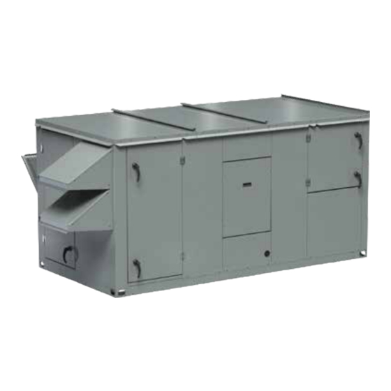
Energy Recovery Ventilator
with Heating and Cooling
DANGER
• Always disconnect power before working on or near
this equipment. Lock and tag the disconnect switch
or breaker to prevent accidental power up.
• If this unit is equipped with optional gas
accessories, turn off gas supply whenever power is
disconnected.
CAUTION
This unit may be equipped with a compressed
refrigerant system. If a leak in the system should
occur, immediately evacuate and ventilate the area.
An EPA Certified Technician must be engaged to
make repairs or corrections. Refrigerant leaks may
also cause bodily harm.
CAUTION
When servicing the unit, the internal components may
be hot enough to cause pain or injury. Allow time for
cooling before servicing.
WARNING
The roof lining contains high voltage wiring. To
prevent electrocution, do not puncture the interior or
exterior panels of the roof.
Energy Recovery Ventilator with Heating and Cooling
Document 476054
Model ERCH
1
Advertisement
Table of Contents

Related Manuals for Greenheck ERCH


Summary of Contents for Greenheck ERCH
-
Page 1: General Safety Information
Document 476054 Model ERCH Energy Recovery Ventilator ® with Heating and Cooling Installation, Operation and Maintenance Manual Please read and save these instructions for future reference. Read carefully before attempting to assemble, install, operate or maintain the product described. Protect yourself and others by observing all safety information. Failure... -
Page 2: Table Of Contents
Table of Contents General Safety Information ..... .1 Receiving, Handling and Storage ....3 Product Overview . -
Page 3: Receiving, Handling And Storage
Receiving the floor. Clearance should be provided to permit air circulation and space for inspection. This product may have been subject to road salt during Outdoor transit. If so, immediately wash off all visible white The unit should be placed on a level surface to prevent reside from all exterior surfaces. -
Page 4: Product Overview
Product Overview The model ERCH combines the benefits of energy as heating or cooling, or their function can be recovery and many combinations of supplemental alternated between heating and cooling by changing heating and cooling. Heating sources include indirect the temperature of the water flowing through the coil. - Page 5 Product Overview Split DX Electric Post-Heaters The unit is equipped with an evaporator coil that The optional post-heater is used as a heat source for will be connected to a separate condensing unit the building and is integrated into the supply airstream. (provided by others).
-
Page 6: Unit Installation
Model Weight Exhaust Outdoor Air Configuration Length Width Height (lbs) Hood Hood Heating Only 76.2 1550 Cooling Coil* 96.2 1825 ERCH-20 54.3 54.2 20.8 17.7 WSHP 2375 Evap Cooling 1800 Heating Only 84.3 2325 Cooling Coil* 104.3 2725 ERCH-45 64.4 70.2... - Page 7 Length Width Adder per inch Vestibule Heating Only 71.8 49.9 12.3 +6.9 +8.3 28.3 Cooling Coil* 91.8 49.9 32.8 +7.7 +9.5 ERCH-20 43.5 WSHP Evap Cooling 28.3 Heating Only 79.9 12.3 +8.0 +9.4 31.8 Cooling Coil* 99.9 32.8 +8.8 +10.6 ERCH-45 54.8...
- Page 8 *Cassette removal only available Model A (in.) B (in.) on housing sizes 20 and 45. ERCH-20 ERCH-45 ERCH-55 ERCH-90 EXHAUST AIR WEATHERHOOD ELECTRICAL BOX...
- Page 9 *Cassette removal only available Model A (in.) B (in.) on housing sizes 20 and 45. ERCH-20 ERCH-45 ERCH-55 ERCH-90 EXHAUST AIR WEATHERHOOD ELECTRICAL BOX...
- Page 10 *Cassette removal only available Model A (in.) B (in.) on housing sizes 20 and 45. ERCH-20 ERCH-45 ERCH-55 ERCH-90 EXHAUST AIR WEATHERHOOD ACCESS PANEL...
- Page 11 *Cassette removal only available Model A (in.) B (in.) on housing sizes 20 and 45. ERCH-20 ERCH-45 ERCH-55 ERCH-90 EXHAUST AIR WEATHERHOOD 52 inches...
- Page 12 Unit Installation Handling Lifting While this unit was constructed with quality and WARNING dependability in mind, damage still may occur during All factory-provided lifting lugs must be used when handling of the unit for installation. Exercise extreme lifting the units. Failure to comply with this safety caution to prevent any damage from occurring to the refrigerant system.
- Page 13 Not available in models with water-source heat pump or evaporative cooling. Position the unit roof opening such that the supply ERCH discharge and exhaust inlet of the unit will line up with the corresponding ductwork. Be sure to allow for the recommended service clearances when positioning opening.
- Page 14 Unit Installation Rail Mounting / Layout ERCH-20 Recommended Duct Size 1. Rails designed to handle the weight of the unit Intake Duct Size Discharge 9-9 Blower 10-6 Blower should be positioned as shown on the diagram (rails 22 x 26...
-
Page 15: Electrical Installation
Electrical Installation 1. Determine the Size of the Main Power Lines WARNING The unit’s nameplate states the voltage and the unit’s The roof lining contains high voltage wiring. To prevent MCA. The main power lines to the unit should be electrocution, do not puncture the interior or exterior sized accordingly. - Page 16 Electrical Installation Field-Provided Disconnect Typical Control Center Components with Microprocessor Control If field-installing an additional disconnect switch, it is recommended that there is at least four feet of service room between the switch and system access panels. When providing or replacing fuses in a fusible disconnect, use dual element time delay fuses and size according to the rating plate.
- Page 17 Electrical Installation Optional Accessory Wiring Schematics Remote Panel Unit Interfacing Terminals Heating/Cooling Switches & Night Setback The remote panel is available with a number of different alarm lights and switches to control the unit. The remote Switch/Timer panel ships loose and requires mounting and wiring in TERMINAL BLOCKS IN UNIT CONTROL CENTER the field.
-
Page 18: Piping Installation
Piping Installation Optional Gas Piping control system can be depended on to be 100% safe against freeze-up with water coils. Glycol solutions Units with indirect gas-fired furnaces require field- or brines are the only safe media for operation of supplied and installed gas supply piping. The unit gas water coils with low entering air conditions. - Page 19 Tonnage pan with a 1-inch MPT stainless steel drain connection. (in. FPT) Connections It is important that the drain connection be fitted with a ERCH-20 P trap to ensure proper drainage of condensate while ERCH-45 maintaining internal static pressures. ERCH-20 A P trap assembly (kit) is 1.25...
- Page 20 Piping Installation Optional Evaporative Cooler 3. Check/Adjust Water Level. Check the water level in the sump tank. The water level should be above the CAUTION pump intake and below the overflow. Adjust the float as needed to achieve the proper water level. All solenoids valves and traps must be installed below the roof to protect the supply water line from freezing.
- Page 21 3/4-inch 461264 8210G35 Open Drain (19.05 mm) Part numbers subject to change. Water Supply Connection Locations for Evaporative Cooler Water Supply Connection Locations Model ERCH-20 37.5 ERCH-45 45.25 44.5 ERCH-55 47.5 ERCH-90 62.5 Dimensions from outside of unit (in inches) Run 1/4 in.
-
Page 22: Unit Overview
Unit Overview Optional Component Overview Basic Unit Economizer The unit is pre-wired such that when a call for outside The energy wheel operation can be altered to take air is made (via field-supplied 24 VAC control signal advantage of economizer operation (free cooling). wired to unit control center), the supply fan, exhaust fan, Two modes are available: and energy wheel are energized and optional motorized... - Page 23 Optional Component Overview Frost Control Variable Frequency Drives (VFD) Extremely cold outdoor air temperatures can cause Variable frequency drives are used to control the speed moisture condensation and frosting on the energy of the fan as either multi-speed or modulating control. recovery wheel.
- Page 24 Optional Component Overview Microprocessor Control Hot Gas Reheat Valve The microprocessor controller is specifically designed Units equipped with a reheat and programmed to optimize the performance of the coil use a three-way valve with unit with supplemental actuator to control the supply air heating and cooling.
- Page 25 Optional Component Overview Smoke Detector Optional Exhaust Fan Only Power The Hochiki America DH-98 duct The exhaust fan will have a dedicated power circuit smoke detector provides early where in the case of a power outage, the exhaust fan detection of smoke and products of will still run.
-
Page 26: Cooling System Overview
Cooling System Overview Water-Source Heat Pump with Three Way Hot Gas Reheat and Hot Gas Bypass Water In Water Out Waterside Coil Supply Airflow 1. Compressor 8. Hot Gas Bypass Check Valve 2. High Limit Pressure Switch 9. Coaxial Refrigerant-to-Water Heat Exchanger The switch opens when refrigerant pressure The unit uses one coaxial heat exchanger per increases above the set point in the discharge line. -
Page 27: Unit Start-Up
Unit Start-Up SPECIAL TOOLS REQUIRED DANGER Electric shock hazard. Can cause injury or death. • Voltage Meter (with wire probes) Before attempting to perform any service or • Amperage Meter maintenance, turn the electrical power to unit to OFF • Pressure Gauges – (refrigerant) at disconnect switch(es). - Page 28 Unit Start-Up Pre Start-Up Every installation requires a comprehensive start-up Check the fan belt drives for proper alignment and to ensure proper operation of the unit. As part of that tension. process, the following checklist must be completed and Filters can load up with dirt during building information recorded.
- Page 29 Unit Start-Up Energy Wheel Motor Amps Amps Amps Cooling System Outdoor Air Relative Outdoor Air Temperature Deg F Humidity % RH Return Air Relative Return Air Temperature Deg F Humidity % RH Heating System / Electric Heat Pre-Heater L1-L2 Volts L2-L3 Volts L1-L3...
- Page 30 Unit Start-Up Optional Accessories Checklist Refer to the respective sections in this Installation, Operation and Maintenance Manual for detailed information. Refer to wiring diagram in unit control center to determine what electrical accessories were provided. Frost Control Application / Operation Section: Setting Factory Default Frost Control set point...
-
Page 31: Start-Up Components
Start-Up Components Energy Wheel Push the wheel cassette back into the unit and plug in the power connector. Turn the main power supply The energy wheel is installed in the unit’s airstream with back on and then observe the operation of the wheel by one half of the wheel in the intake airstream and one opening the wheel access door slightly. - Page 32 Max RPM Max RPM damage to the cords in the belts. 2 in. 10 x 6 1700 6. With the fan off, adjust the belt tension ERCH-20 Pulley 9 x 9 1750 2800 by moving the motor base. (See belt alignment...
-
Page 33: Optional Start-Up Components
Optional Start-Up Components Dirty Filter Switch Using the Keypad with Settings and Parameters To use the keypad when working with Set Points, To adjust the switch, the unit must be running with System and Advanced Settings, Checkout Tests, and all of the access doors in place, except for the Alarms: compartment where the switch is located (exhaust 1. - Page 34 Optional Start-Up Components Stop Wheel Frost Control 1. Navigate to the Checkout menu and press (enter). Timed Exhaust 2. The energy wheel and cooling should stop. 1. Remove power from unit. 3. Navigate to Connect ERV and press (enter) twice 2.
- Page 35 Optional Start-Up Components Outdoor Airflow Monitor 8. Measure the supply airflow rate of the unit using an approved test and balance method. For additional information on how to navigate through the airflow controller menus, refer to technical manuals 9. Without making any changes to the system, GF-2200A from GreenTrol®...
- Page 36 Optional Start-Up Components Evaporative Cooler Set the Timer Scale and Settings dials: • t timer setting set to 10 and timer scale set to 1. Check the Installation. The media may have been 1d for 1 day of operation removed during installation, so its orientation should be double •...
- Page 37 Most of the set points USER TO PROVIDE ISOLATION AS REQUIRED in the VFDs are Yaskawa factory defaults. However, a few set points are changed at Greenheck and are shown 0-10 VDC CONTROL SIGNAL (BY OTHERS) ON 1 - 0-10 VDC CONTROL...
- Page 38 Optional Start-Up Components Modulating Control for Fan Speed Proportional Control (0-10 VDC) Setting Setting Parameter Parameter V1000 J1000 V1000 J1000 A1-01 Access Level B1-17 VFD Start-Up Setting B1-17 VFD Start-Up Setting C6-02 Carrier Frequency C6-02 Carrier Frequency D2-02 Ref Lower Limit D2-02 Ref Lower Limit E2-01...
-
Page 39: Routine Maintenance
Routine Maintenance Annually DANGER It is recommended that the annual inspection and Electric shock hazard. Can cause injury or death. maintenance occur at the start of the cooling season. Before attempting to perform any service or After completing the checklist, follow the unit start- maintenance, turn the electrical power to the unit to up checklist provided in the manual to ensure the OFF at disconnect switch(es). - Page 40 Routine Maintenance Maintenance Procedures span (measured half-way between sheave centers). For example, if the belt span is 64 inches, the belt deflection WARNING should be one inch (using moderate thumb pressure at mid-point of the drive). Check belt tension two times REFER TO GENERAL SAFETY INFORMATION during the first 24 hours of operation and periodically Do not operate this unit without the filters and...
- Page 41 (inches) Supply Exhaust plugging the drain and causing the drain pan to ERCH-20 20 x 20 overflow. Inspect twice a year to avoid the possibility ERCH-45 20 x 25 of overflow. Also, drain pans should be kept clean to...
- Page 42 Routine Maintenance Energy Wheel Maintenance Cleaning Maintenance or cleaning of the wheel segments WARNING should be done with the segments removed from the wheel cassette to avoid splashing liquids or Whenever performing maintenance or inspections, cleaning agents inside the cabinet. If the energy wheel always disconnect the power source.
- Page 43 Routine Maintenance Evaporative Cooling Maintenance h. Clean all remaining components (i.e. sump, pump, etc.) of any mineral deposits or foreign Regularly scheduled maintenance is the key to peak materials. performance, minimized cost, and extended life of the i. Replace all worn or non-functioning parts. evaporative cooler.
-
Page 44: Troubleshooting
Troubleshooting – Unit Symptom Possible Cause Corrective Action Blown fuse or open circuit breaker. Replace fuse or reset circuit breaker and check amps. Defective motor or capacitor. Replace. Blower fails to Motor overloaded. Reset VFD and check amps. operate Check for On/Off switches. Check for correct supply voltage. Electrical. - Page 45 Troubleshooting – Refrigeration Circuit TROUBLESHOOTING NOTE IMPORTANT Do not release refrigerant to the atmosphere! If Before any components are changed on the required service procedures include the adding or refrigeration system, the cause of the failure must be removing of refrigerant, the service technician must identified.
- Page 46 Troubleshooting – Refrigeration Circuit Symptom Possible Cause Corrective Action Refrigerant overcharge. Check pressures, charge by subcooling. Compressor starts but Check high side equalized pressures, check thermal expansion Air or non-condensables in system. cuts out on valves. high pressure Defective high pressure switch. Replace.
- Page 47 Troubleshooting – Refrigeration Circuit Symptom Possible Cause Corrective Action Check for high entering wet bulb temperature, check for Excessive load on evaporator coil. excessive air flow. Compressor is unloaded. Check digital scroll controller signal and solenoid valve. (digital scroll) Check the thermal expansion valve, ensure bulb is insulated. Check superheat.
- Page 48 Troubleshooting – Refrigeration Circuit Symptom Possible Cause Corrective Action Thermostat location or controls malfunction. Check thermostat, check heat anticipator setting. Improper refrigerant charge. Check subcooling, verify superheat. Defective low pressure control. Check high or low pressure switch. Compressor Poor air distribution. Check ductwork for recirculating.
- Page 49 Troubleshooting – Evaporative Cooling Symptom Possible Cause Corrective Action Check water level in sump pan. Water level should be Water level in sump pan too low. maintained at greater than one inch. Check the pump filter at the inlet. Clean the filter if Pump filter clogged.
- Page 50 Troubleshooting – Evaporative Cooling Symptom Possible Cause Corrective Action Pad installed backwards. To get the performance from the cooling pads, they must be installed properly. The pads are manufactured with 15/45 degree flute angles. The pads must always be installed with the steeper flute angle sloping down toward the entering air side.
- Page 51 Troubleshooting Troubleshooting Controller Alarms Rotation Sensor The first step in troubleshooting the unit is to check When the unit is first turned on, the LED on the back of the on-board alarm indicators. Several of the electronic the sensor should turn on and stay on with the wheel controls in the unit monitor the system for faults and will running.
- Page 52 Maintenance Manuals for additional details. All are available at www.greenheck.com Low pressure lockout Compressor 1 • DDC Controller for Energy Recovery High pressure lockout • ERCH Curbs Compressor 2 • PVF/PVG Indirect Gas-Fired Heat Modules Dual Low pressure lockout Compressor...
-
Page 53: Reference
Flue Connection Size (diameter in inches) Housing Furnace Size Standard Non-Concentric Concentric (MBH) Size Exhaust Exhaust Intake Exhaust Intake 12.42 24.20 20.05 23.21 ERCH-20 12.42 24.20 20.05 23.21 12.63 24.42 20.25 23.52 12.63 24.42 20.25 23.52 ERCH-45 24.94 24.32 33.87 21.21... -
Page 54: Maintenance Log
Maintenance Log Date ___________________Time _____________ AM/PM Date ___________________Time _____________ AM/PM Notes: ___________________________________________ Notes: ___________________________________________ _________________________________________________ _________________________________________________ _________________________________________________ _________________________________________________ _________________________________________________ _________________________________________________ _________________________________________________ _________________________________________________ Date ___________________Time _____________ AM/PM Date ___________________Time _____________ AM/PM Notes: ___________________________________________ Notes: ___________________________________________ _________________________________________________ _________________________________________________ _________________________________________________ _________________________________________________ _________________________________________________ _________________________________________________ _________________________________________________ _________________________________________________ Date ___________________Time _____________ AM/PM... - Page 55 Maintenance Log Date ___________________Time _____________ AM/PM Date ___________________Time _____________ AM/PM Notes: ___________________________________________ Notes: ___________________________________________ _________________________________________________ _________________________________________________ _________________________________________________ _________________________________________________ _________________________________________________ _________________________________________________ _________________________________________________ _________________________________________________ Date ___________________Time _____________ AM/PM Date ___________________Time _____________ AM/PM Notes: ___________________________________________ Notes: ___________________________________________ _________________________________________________ _________________________________________________ _________________________________________________ _________________________________________________ _________________________________________________ _________________________________________________ _________________________________________________ _________________________________________________ Date ___________________Time _____________ AM/PM...
-
Page 56: Our Commitment
Our Commitment As a result of our commitment to continuous improvement, Greenheck reserves the right to change specifications without notice. Specific Greenheck product warranties are located on greenheck.com within the product area tabs and in the Library under Warranties. Greenheck catalog Energy Recovery Ventilator Model ERCH,...
Need help?
Do you have a question about the ERCH and is the answer not in the manual?
Questions and answers