
Related Manuals for Basler BE1-51B-219


Summary of Contents for Basler BE1-51B-219
- Page 1 INSTRUCTION MANUAL OVERCURRENT RELAYS BE1-50/51B-219 and BE1-50/51B-226 Publication: 9252000981 Revision: G 03/08...
- Page 3 INTRODUCTION This instruction manual provides information about the operation and installation of the BE1-50/51B-219 and BE1-50/51B-226 Overcurrent Relays. To accomplish this, the following information is provided: • General Information and Specifications • Controls and Indicators • Functional Description • Installation and Maintenance •...
- Page 4 March 2008 CONFIDENTIAL INFORMATION of Basler Electric, Highland Illinois, USA. It is loaned for confidential use, subject to return on request, and with the mutual understanding that it will not be used in any manner detrimental to the interest of Basler Electric.
- Page 5 REVISION HISTORY The following information provides a historical summary of the changes made to this instruction manual (9252000981). Revisions are listed in reverse chronological order. Manual Revision and Date Change • G, 03/08 Updated front panel drawings. • F, 01/07 Moved Time Characteristic Curve Figures to Appendix A.
- Page 6 This page intentionally left blank. BE1-50/51B-219/-226 Introduction 9252000981 Rev G...
-
Page 7: Table Of Contents
CONTENTS SECTION 1 • GENERAL INFORMATION ....................1-1 SECTION 2 • CONTROLS AND INDICATORS ..................2-1 SECTION 3 • FUNCTIONAL DESCRIPTION ................... 3-1 SECTION 4 • INSTALLATION ........................4-1 SECTION 5 • TESTING ..........................5-1 APPENDIX A • TIME CHARACTERISTIC CURVES................A-1 9252000981 Rev G BE1-50/51B-219/-226 Introduction... - Page 8 This page intentionally left blank. BE1-50/51B-219/-226 Introduction 9252000981 Rev G...
- Page 9 SECTION 1 • GENERAL INFORMATION TABLE OF CONTENTS SECTION 1 • GENERAL INFORMATION ....................1-1 INTRODUCTION............................ 1-1 FEATURES ............................1-1 Advantages............................1-2 SPECIFICATIONS ..........................1-2 Current Sensing Input ........................1-2 Time Overcurrent (51) Element......................1-2 Instantaneous Overcurrent (50) Element ................... 1-5 Burden ..............................
- Page 10 This page intentionally left blank. BE1-50/51B-219/-226 General Information 9252000981 Rev G...
-
Page 11: Table 1-1. Abb Relays Suitable For Direct Replacement
3. Insert the new relay cradle. 4. Close the knife-blade switches. 5. Install the new Basler Electric cover and secure with the captive thumbnut. Basler Electric BE1-50/51B-219 and BE1-50/51B-226 protective relays are self-powered, microprocessor- based, non-directional phase or ground relays that monitor the magnitude of a single-phase ac current to provide accurate instantaneous and time overcurrent protection for 50 Hz or 60 Hz power systems. -
Page 12: Current Sensing Input
type curves, and instantaneous or integrating reset characteristics. Switch location and description is provided in Section 2. Advantages BE1-50/51B-219 and BE1-50/51B-226 overcurrent relays have many advantages over other overcurrent relays. The primary advantages are. • Time characteristics are defined by equations and graphs •... -
Page 13: Table 1-2. Time Characteristic Curve Constants With Sw3-3 Open (Off)
Timing Accuracy Example (BE1-50/51B-219) PU setting: 5 amperes Current Applied: 6.5 amperes + Multiple Tolerance: 6.655 amperes – Multiple Tolerance: 6.345 amperes Time Curve: Time Dial: Minimum time dial using 6.655 amperes: 46.5470 seconds Maximum time dial using 6.345 amperes: 61.3968 seconds Curve time using 6.5 amperes: 53.1800 seconds Curve Characteristics... -
Page 14: Table 1-3. Time Characteristic Curve Constants With Sw3-3 Closed (On)
Table 1-3. Time Characteristic Curve Constants with SW3-3 Closed (On) Curve Type ∗ Constants Figure Number † Similar To GE IAC 55 A-10 0.0286 0.0208 1.000 0.9844 0.028 0.0940 GE IAC 66 A-11 2.3955 0.00002 1.000 0.3125 0.028 7.8001 ABB CO-6 0.4797 0.21359 1.000... -
Page 15: Instantaneous Overcurrent (50) Element
100.0 10.0 0.000 0.200 0.400 0.600 0.800 1.000 1.200 Multiple of Pickup Vertical axis xRD (Seconds) is applicable for all curves and is derived from multiplying the constant R for the curve selected times D (the Time Dial setting). Figure 1-1. Integrating Reset Characteristic Curve Instantaneous Overcurrent (50) Element Setting the INST PICKUP at the minimum pickup setting places the relay in the most sensitive state and may be used as a safety setting. -
Page 16: Burden
Figure 1-2. Instantaneous Characteristic Curves Burden Burden is non-linear. Figure 1-3 illustrates the device burden. BE1-50/51B-219 4.8 Ω At 0.5 amperes: 0.2 Ω At 5.0 amperes: BE1-50/51B-226 120 Ω At 0.1 ampere: 5 Ω At 1.0 ampere: BE1-50/51B-219/-226 General Information 9252000981 Rev G... -
Page 17: Frequency Response
Figure 1-3. Burden Characteristics Frequency Response A change of ±5 Hz from the nominal 50/60 Hz current causes <0.5% change in the current required for pickup. Transient Response <10% overreach with system time constants up to 40 ms. Harmonic Response Figure 1-4 shows that a relay set for 1 ampere pickup would pick up at 0.96 amperes with a current containing 40% seventh harmonic. -
Page 18: Target Indicators
Figure 1-4. Harmonic Rejection Target Indicators Gravity latched, manually reset targets indicate that current of 0.2 amperes or greater was present in the trip circuit. Target coil resistance is less than 0.1 ohms and operate time is less than one millisecond. See Output Contacts for maximum current rating. -
Page 19: Environment
Radio Frequency Interference (RFI) Field-tested using a 5-watt, hand-held transceiver operating at random frequencies centered around 144 MHz and 440 MHz, with the antenna located 6 inches from the relay in both horizontal and vertical planes. Vibration Withstands 2 G in each of three mutually perpendicular planes swept over the range of 10 to 500 Hz for a total of 6 sweeps, 15 minutes each sweep. - Page 20 This page intentionally left blank. 1-10 BE1-50/51B-219/-226 General Information 9252000981 Rev G...
-
Page 21: Section 2 • Controls And Indicators
SECTION 2 • CONTROLS AND INDICATORS TABLE OF CONTENTS SECTION 2 • CONTROLS AND INDICATORS ..................2-1 INTRODUCTION............................ 2-1 Figures Figure 2-1. Front Panel Controls and Indicators ..................2-1 Figure 2-2. Location of SW3........................2-2 Tables Table 2-1. BE1-50/51B-219 and BE1-50/51B-226 Controls and Indicators..........2-3 9252000981 Rev G BE1-50/51B-219/-226 Controls and Indicators... - Page 22 This page intentionally left blank. BE1-50/51B-219/-226 Controls and Indicators 9252000981 Rev G...
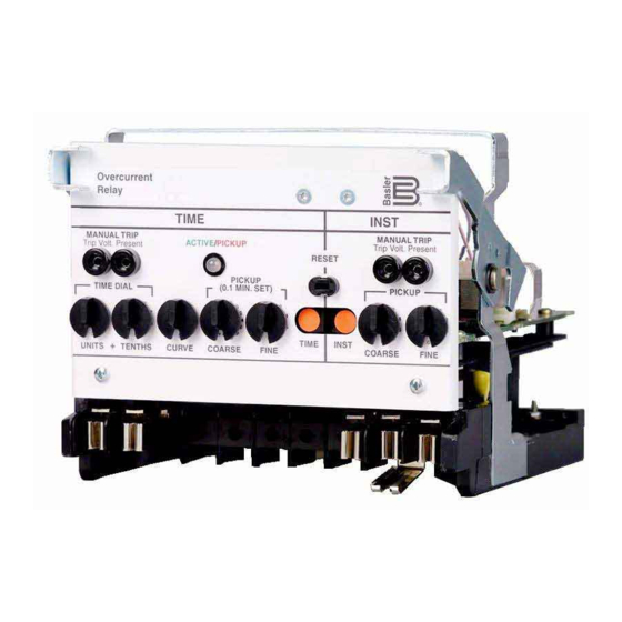
- Page 23 SECTION 2 • CONTROLS AND INDICATORS INTRODUCTION Figure 2-1 illustrates the front panel controls and indicators of the BE1-50/51B-219 and BE1-50/51B-226. Figure 2-2 illustrates the location of switch SW3. Both illustrations have lettered call-outs that correspond to the control and indicator descriptions provided in Table 2-1. Figure 2-1.
- Page 24 Figure 2-2. Location of SW3 BE1-50/51B-219/-226 Controls and Indicators 9252000981 Rev G...
- Page 25 Table 2-1. BE1-50/51B-219 and BE1-50/51B-226 Controls and Indicators (Refer to Figures 2-1 and 2-2) Locator Control or Indicator Function INST MANUAL TRIP When shorted, the test points (jacks) provide a secure means to Test Points manually trip the controlled breaker. Jacks accept a standard 0.08 inch diameter phone tip plug.
- Page 26 This page intentionally left blank. BE1-50/51B-219/-226 Controls and Indicators 9252000981 Rev G...
-
Page 27: Section 3 • Functional Description
SECTION 3 • FUNCTIONAL DESCRIPTION TABLE OF CONTENTS SECTION 3 • FUNCTIONAL DESCRIPTION ................... 3-1 GENERAL .............................. 3-1 FUNCTIONAL DESCRIPTION ......................3-1 Sensing Input............................3-1 Power Supply ............................. 3-1 Instantaneous Signal.......................... 3-1 Time Signal............................3-1 Microprocessor ........................... 3-1 Power-Off Sensing ..........................3-1 Outputs ............................... - Page 28 This page intentionally left blank. BE1-50/51B-219/-226 Functional Description 9252000981 Rev G...
- Page 29 SECTION 3 • FUNCTIONAL DESCRIPTION GENERAL BE1-50/51B-219 and BE1-50/51B-226 Overcurrent Relays are microprocessor based non-directional relays that measure ac current to provide secure and reliable instantaneous and time overcurrent protection for power systems. FUNCTIONAL DESCRIPTION Sensing Input Single phase ac current from system current transformers (CT) is brought into the Overcurrent Relay at terminals 8 and 9.
- Page 30 Outputs Instantaneous and Timed System circuit breakers controlled by the output contacts can be manually tripped by applying a short across the TIME or INST MANUAL TRIP front panel test points. Current flow in the trip circuit is indicated by the operation of the target. The targets will not operate without adequate operating power for the relay. CAUTION Trip circuit voltage is present at the front panel test points.
-
Page 31: Section 4 • Installation
SECTION 4 • INSTALLATION TABLE OF CONTENTS SECTION 4 • INSTALLATION ........................4-1 GENERAL .............................. 4-1 FACTORY SETTINGS........................... 4-1 INSTALLATION............................4-1 APPLICATION COORDINATION ......................4-1 CONNECTIONS ............................ 4-3 MAINTENANCE ............................. 4-4 STORAGE.............................. 4-4 Figures Figure 4-1. Coordination Timing Diagram ....................4-2 Figure 4-2. - Page 32 This page intentionally left blank. BE1-50/51B-219/-226 Installation 9252000981 Rev G...
- Page 33 • Close knife-blade switches. • To install the cover, position the interlocking bracket at the top of the new Basler Electric cover into the mating receptacle at the top of the case. Secure the captive fastener at the bottom of the cover.
- Page 34 occurs (magnitude ten times pickup), calculate the feeder breaker trip time for each of the three operations. Refer to Section 1 for characteristic curve constants. From the time characteristic curve equation. Trip − × 7624 × 02758 0938 − 5248 05516 −...
- Page 35 Equation for time to trip during rewind (before relay is reset). Full Trip Rewind Time Trip This Occurence Full Rewind Second Operation )( ) 0.209 15.5 0.040 seconds Third Operation 0.209 11.96 15.5 0.161 seconds CONNECTIONS Typical ac input and dc control connections are shown in Figures 4-2 and 4-3. Refer to the block diagram in Section 3 for relay internal connections.
- Page 36 A recommended periodic test is provided in Section 5. If the relay fails to function properly, contact the Technical Sales Support Department of Basler Electric. STORAGE This protective relay contains long-life, aluminum, electrolytic capacitors. Life in excess of 20 years may be expected if the storage temperature does not exceed 40°C (104°F).
-
Page 37: Section 5 • Testing
SECTION 5 • TESTING TABLE OF CONTENTS SECTION 5 • TESTING ..........................5-1 GENERAL .............................. 5-1 DIELECTRIC TEST ..........................5-1 OPERATIONAL TEST PROCEDURE ....................5-1 Test Equipment Required........................5-1 Test Procedure, Models BE1-50/51B-218 (Five Ampere Sensing Input) .......... 5-3 Test Procedure, Models BE1-50/51B-228 (One Ampere Sensing Input) .......... 5-5 SETTING THE RELAY .......................... - Page 38 This page intentionally left blank. BE1-50/51B-219/-226 Testing 9252000981 Rev G...
-
Page 39: Section 5 • Testing
SECTION 5 • TESTING GENERAL Dielectric testing, operational testing, and periodic testing are described in the following paragraphs. DIELECTRIC TEST In accordance with IEC 255-5 and IEEE C37.90-1989, one-minute dielectric (high potential) tests may be performed as follows: All circuits to ground: 2,828 Vdc. - Page 40 Figure 5-1. Pickup and Timing Test Setup TEST SET CURRENT AMPS SOURCE BE1-50/51B-219 TIME INST START STOP TIMER 1.0 Aac INPUT CURRENT LIMITER D2354-20 TARGET CURRENT 12-13-99 Figure 5-2. Target Operational Test Setup BE1-50/51B-219/-226 Testing 9252000981 Rev G...
-
Page 41: Test Procedure, Models Be1-50/51B-218 (Five Ampere Sensing Input)
NOTE When testing TIME overcurrent functions, INST PICKUP settings of 00 will affect the calibration of the TIME functions. TIME PICKUP settings of 00 also affect INST functions. Test Procedure, Models BE1-50/51B-216 (Five Ampere Sensing Input) Time Pickup Test Perform preliminary setup: •... - Page 42 Step 1. Prepare to apply 1.5 amperes input current to terminals 8 and 9 and record the elapsed time from when current is applied until TIME output contacts close. Step 2. Apply the current (step from 0 to 1.5 amperes) and record the elapsed time. Elapsed time should be 0.345 to 0.424 seconds.
-
Page 43: Test Procedure, Models Be1-50/51B-228 (One Ampere Sensing Input)
Step 1. Set target current source to 1.0 ampere, ac. Step 2. Read all of Step 3 before beginning Step 3. Step 3. Apply 4.0 amperes input current to terminals 8 and 9. After the unit trips, remove the input current for 29 ±0.25 seconds, then reapply the 4.0 amperes input current. - Page 44 Step 1. Prepare to apply 0.3 amperes input current to terminals 8 and 9 and record the elapsed time from when current is applied until TIME output contacts close. Step 2. Apply the current (step from 0 to 0.3 amperes) and record the elapsed time. Elapsed time should be 1.754 to 2.084 seconds.
-
Page 45: Setting The Relay
Step 1. Set target current source to 1.0 ampere, ac. Step 2. Read all of Step 3 before beginning Step 3. Step 3. Apply 0.8 amperes input current to terminals 8 and 9. After the unit trips, remove the input current for 20 ±0.25 seconds, then reapply the 0.8 amperes input current. - Page 46 This page intentionally left blank. BE1-50/51B-219/-226 Testing 9252000981 Rev G...
- Page 47 APPENDIX A • TIME CHARACTERISTIC CURVES TABLE OF CONTENTS APPENDIX A • TIME CHARACTERISTIC CURVES................A-1 TIME CHARACTERISTIC CURVES......................A-1 Figures Figure A-1. Time Characteristic Curve, S-Short Inverse (SW3-3 OFF, Similar to ABB CO-2) ....A-1 Figure A-2. Time Characteristic Curve, L-Long Inverse (SW3-3 OFF, Similar to ABB CO-5) ....A-2 Figure A-3.
- Page 48 This page intentionally left blank. BE1-50/51B-219/-226 Time Characteristic Curves 9252000981 Rev G...
-
Page 49: Appendix A • Time Characteristic Curves
APPENDIX A • TIME CHARACTERISTIC CURVES TIME CHARACTERISTIC CURVES Figures A-1 through A-14 illustrate the time characteristic curves that are programmed into the nonvolatile memory of this relay. Figure A-1. Time Characteristic Curve, S-Short Inverse (SW3-3 OFF, Similar to ABB CO-2) 9252000981 Rev G BE1-50/51B-219/-226 Time Characteristic Curves... - Page 50 Figure A-2. Time Characteristic Curve, L-Long Inverse (SW3-3 OFF, Similar to ABB CO-5) BE1-50/51B-219/-226 Time Characteristic Curves 9252000981 Rev G...
- Page 51 Figure A-3. Time Characteristic Curve, D-Definite Time (Similar to ABB CO-6) 9252000981 Rev G BE1-50/51B-219/-226 Time Characteristic Curves...
- Page 52 Figure A-4. Time Characteristic Curve, M-Moderately Inverse (Similar to ABB CO-7) BE1-50/51B-219/-226 Time Characteristic Curves 9252000981 Rev G...
- Page 53 Figure A-5. Time Characteristic Curve, I-Inverse (SW3-3 OFF, Similar to ABB CO-8) 9252000981 Rev G BE1-50/51B-219/-226 Time Characteristic Curves...
- Page 54 Figure A-6. Time Characteristic Curve, V-Very Inverse (SW3-3 OFF, Similar to ABB CO-9) BE1-50/51B-219/-226 Time Characteristic Curves 9252000981 Rev G...
- Page 55 Figure A-7. Time Characteristic Curve, E-Extremely Inverse (SW3-3 OFF, Similar to ABB CO-11) 9252000981 Rev G BE1-50/51B-219/-226 Time Characteristic Curves...
- Page 56 Figure A-8. Time Characteristic Curve, BS142-B (BS142 Very Inverse) BE1-50/51B-219/-226 Time Characteristic Curves 9252000981 Rev G...
- Page 57 Figure A-9. Time Characteristic Curve, BS142-C (BS142 Extremely Inverse) 9252000981 Rev G BE1-50/51B-219/-226 Time Characteristic Curves...
- Page 58 Figure A-10. Time Characteristic Curve, S2-Short Inverse (SW3-3 ON, Similar to GE IAC 55) A-10 BE1-50/51B-219/-226 Time Characteristic Curves 9252000981 Rev G...
- Page 59 Figure A-11. Time Characteristic Curve, L2-Long Inverse (SW3-3 ON, Similar to GE IAC 66) 9252000981 Rev G BE1-50/51B-219/-226 Time Characteristic Curves A-11...
- Page 60 Figure A-12. Time Characteristic Curve, I2-Inverse (SW3-3 ON, Similar to GE IAC 51) A-12 BE1-50/51B-219/-226 Time Characteristic Curves 9252000981 Rev G...
- Page 61 Figure A-13. Time Characteristic Curve, V2-Very Inverse (SW3-3 ON, Similar to GE IAC 53) 9252000981 Rev G BE1-50/51B-219/-226 Time Characteristic Curves A-13...
- Page 62 Figure A-14. Time Characteristic Curve, E2-Extremely Inverse (SW3-3 ON, Similar to GE IAC 77) A-14 BE1-50/51B-219/-226 Time Characteristic Curves 9252000981 Rev G...
- Page 63 ROUTE 143, BOX 269 HIGHLAND, IL 62249 USA http://www.basler.com, info@basler.com PHONE +1 618-654-2341 FAX +1 618-654-2351...
Need help?
Do you have a question about the BE1-51B-219 and is the answer not in the manual?
Questions and answers