Table of Contents
Advertisement
Advertisement
Table of Contents

Subscribe to Our Youtube Channel
Related Manuals for LTS LTN8608-P8


Summary of Contents for LTS LTN8608-P8
- Page 1 Network Video Recorder Quick Start Guide...
-
Page 2: Table Of Contents
Network Video Recorder Quick Start Guide TABLE OF CONTENTS Chapter1 Description of Panels ........................6 Front Panel ............................6 Rear Panel ............................10 Chapter 2Installation and Connections ......................12 NVR Installation ..........................12 Hard Disk Installation ........................12 Connections ........................... 14 Wiring of Alarm Input ........................ - Page 3 Network Video Recorder Quick Start Guide Quick Start Guide About this Manual This Manual is applicable to Network Video Recorder (NVR). The Manual includes instructions for using and managing the product. Pictures, charts, images and all other information hereinafter are for description and explanation only. The information contained in the Manual is subject to change, without notice, due to firmware updates or other reasons.
-
Page 4: Regulatory Information
Network Video Recorder Quick Start Guide Regulatory Information FCC Information FCC compliance: This equipment has been tested and found to comply with the limits for a Class A digital device, pursuant to part 15 of the FCC Rules. These limits are designed to provide reasonable protection against harmful interference when the equipment is operated in a commercial environment. -
Page 5: Safety Instruction
Network Video Recorder Quick Start Guide Safety Instruction These instructions are intended to ensure that user can use the product correctly to avoid danger or property loss. The precaution measure is divided into “Warnings” and “Cautions” Warnings: Serious injury or death may occur if any of the warnings are neglected. Cautions: Injury or equipment damage may occur if any of the cautions are neglected. - Page 6 Network Video Recorder Quick Start Guide Applicable Models This manual is applicable to the models listed in the following table. Model LTN8608-P8 LTN8616-P16 LTN8916 LTN8932 LTN8916-P16 LTN8932-P16 Symbol Conventions The symbols that may be found in this document are defined as follows.
-
Page 7: Chapter1 Description Of Panels
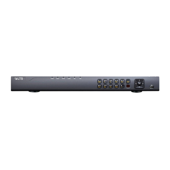
Network Video Recorder Quick Start Guide Chapter1 Description of Panels 1.1 Front Panel Figure 1. 1 Front Panel of LTN86XX series Table 1. 1 Description of Interfaces Name Function Description POWER Turns green when NVR is powered up. READY The LED is green when the device is running normally. The light is green when the IR remote control is enabled;... - Page 8 Network Video Recorder Quick Start Guide Name Function Description Switch between the numeric or letter input and functions of the SHIFT composite keys. (Input letter or numbers when the light is out; Realize functions when the light is red.) Enter numeral “1”; 1/MENU Access the main menu interface.
- Page 9 Network Video Recorder Quick Start Guide Figure 1. 2 Front Panel of LTN89XX series Table 1. 2 Description of Interfaces Name Function Description POWER Turns green when NVR is powered up. READY The LED is green when the device is running normally. The light is green when the IR remote control is enabled;...
- Page 10 Network Video Recorder Quick Start Guide Name Function Description Enter letters “ABC”; The F1 button when used in a list field will select all items in the list. In PTZ Control mode, it will turn on/off PTZ light and when the image is zoomed in, the key is used to zoom out.
-
Page 11: Rear Panel
Network Video Recorder Quick Start Guide 1.2 Rear Panel Figure 1. 3 LTN8608-P8 Figure 1. 4 LTN8616-P16 Table 1. 3 Description of Rear Panel Interfaces Name Description Audio In RCA connector for audio input. Audio Out RCA connector for audio output. - Page 12 Network Video Recorder Quick Start Guide Figure 1. 5 LTN89XX Figure 1. 6 LTN89XX-P16 Table 1. 4 Description of Rear Panel Interfaces Item Description LAN Interface 2 network interfaces AUDIO OUT RCA connector for audio output. LINE IN RCA connector for audio input. HDMI HDMI video output connector.
-
Page 13: Chapter 2Installation And Connections
Network Video Recorder Quick Start Guide Chapter 2 Installation and Connections 2.1 NVR Installation During installation of the NVR: 1. Use brackets for rack mounting. 2. Ensure ample room for audio and video cables. 3. When routing cables, ensure that the bend radius of the cables are no less than five times than its diameter. 4. - Page 14 Network Video Recorder Quick Start Guide Figure 2. 2 Connect the data cable 3. Connect the power cable to the HDD. Figure 2. 3 Connect the power cable 4. Re-install the NVR cover and fasten screws.
-
Page 15: Connections
Network Video Recorder Quick Start Guide 2.3 Connections Wiring of Alarm Input The alarm input is an open/closed relay. To connect the alarm input to the device, use the following diagram. If the alarm input is not an open/close relay, please connect an external relay between the alarm input and the device. -
Page 16: Using Alarm Connectors
Network Video Recorder Quick Start Guide Using Alarm Connectors To connect alarm devices to the NVR: 1. Disconnect pluggable block from the ALARM IN /ALARM OUT terminal block. 2. Unfasten stop screws from the pluggable block, insert signal cables into slots and fasten stop screws. Ensure signal cables are tight. -
Page 17: Hdd Storage Calculation Chart
Network Video Recorder Quick Start Guide 2.4 HDD Storage Calculation Chart The following chart shows an estimation of storage space used based on recording at one channel for an hour at a fixed bit rate. Bit Rate Storage Used 128K 160K 192K 224K... -
Page 18: Chapter 3Menu Operation
Network Video Recorder Quick Start Guide Chapter 3 Menu Operation 3.1 Menu Structure Refer to the following figure for the menu structure: Menu Playback Shutdown Export VCA Search Record Camera Configuration Maintenance Manual Behavior Normal Normal Schedule Camera General System Info Logout Record General... -
Page 19: Activating Your Device
Network Video Recorder Quick Start Guide To shut down the NVR: 1. Enter the Shutdown menu. Menu > Shutdown Figure 3. 2 Shutdown 2. Select the Shutdown button. 3. Click the Yes button. 3.3 Activating Your Device Purpose: For the first-time access, you need to activate the device by setting an admin password. No operation is allowed before activation. -
Page 20: Login And Logout
Network Video Recorder Quick Start Guide device starts up. You can click YES and follow the wizard to set a strong password. Figure 3. 4 Warning of Weak Password 3.4 Login and Logout User Login Purpose: If NVR has logged out, you must login the device before operating the menu and other functions. Steps: Select the User Name in the dropdown list. -
Page 21: User Logout
Network Video Recorder Quick Start Guide User Logout Purpose: After logging out, the monitor turns to the live view mode and if you want to perform any operations, you need to enter user name and password log in again. Steps: Enter the Shutdown menu. -
Page 22: Network Settings
Network Video Recorder Quick Start Guide 3.6 Network Settings Purpose: Network settings must be properly configured before you operate NVR over network. Steps: 1. Enter the Network Settings interface. Menu > Configuration > Network Figure 3. 9 Network Settings Two self-adaptive 10M/100M/1000M network interfaces provided for LTN89XX, and two working modes are configurable: multi-address and network fault tolerance. - Page 23 Network Video Recorder Quick Start Guide Steps: 1. Click to select an idle window in the live view mode. 2. Click the icon in the center of the windw to pop up the adding IP camera interface. 3. Select the detected IP camera and click the Add button to add it directly, and you can click the Search button to refresh the online IP camera manually.
- Page 24 Network Video Recorder Quick Start Guide 2) You can edit the IP address, protocol, management port, and other information of the IP camera to be added. If the IP camera to add has not been actiavated, you can activate it from the IP camera list on the camera management interface.
-
Page 25: Live View
Network Video Recorder Quick Start Guide 3.8 Live View Icons are provided on screen in Live View mode to indicate camera status. These icons include: Live View Icons In the live view mode, there are icons at the upper-right corner of the screen for each channel, showing the status of the record and alarm in the channel for quick reference. - Page 26 Network Video Recorder Quick Start Guide Steps: 1. Enter playback interface. Click menu>playback or from the right-click menu. 2. Check the checkbox of channel(s) in the channel list and then double-click to select a date on the calendar. 3. You can use the toolbar in the bottom part of Playback interface to control playing progress. Figure 3.
-
Page 27: Chapter 4Accessing By Web Browser
Network Video Recorder Quick Start Guide Chapter 4 Accessing by Web Browser You shall acknowledge that the use of the product with Internet access might be under network security risks. For avoidance of any network attacks and information leakage, please strengthen your own protection. If the product does not work properly, please contact with your dealer or the nearest service center. - Page 28 Network Video Recorder Quick Start Guide Figure 4. 2 Login Install the plug-in before viewing the live video and managing the camera. Please follow the installation prompts to install the plug-in. You may have to close the web browser to finish the installation of the plug-in. After login, you can perform the operation and configuration of the device, including the live view, playback, log search, configuration, etc.
Need help?
Do you have a question about the LTN8608-P8 and is the answer not in the manual?
Questions and answers