Table of Contents
Advertisement
Quick Links
Advertisement
Table of Contents

Related Manuals for Moxa Technologies VPort D351


Summary of Contents for Moxa Technologies VPort D351
- Page 1 Moxa Industrial Video Decoder VPort D351 Quick Installation Guide First Edition, November 2007 Moxa Networking Co., Ltd. Tel: +886-2-8919-1230 Fax: +886-2-8919-1231 www.moxa.com support@moxa.com (Worldwide) support@usa.moxa.com (The Americas) P/N:1802003511010 - 1 -...
-
Page 2: Package Checklist
2 DIs located on the top panel to build 2 control buttons for up and down video source selection. Package Checklist The Moxa VPort D351 is shipped with the items listed below. If any of these items is missing or damaged, please contact your customer service representative for assistance. - Page 3 1 RS-232/422/485 PTZ port with serial-to-Ethernet Real COM mode for remote PTZ control with exiting legacy PTZ control device (PTZ control driver NOT required) Capability to decode different video stream resolutions from video encoder with maximum 540 TVL lines Maximum of 64 video sources can be set up as the decode video source Can manually select the video source, or setup automatic scanning for video sources Supports switching the video source using the 2 digital inputs...
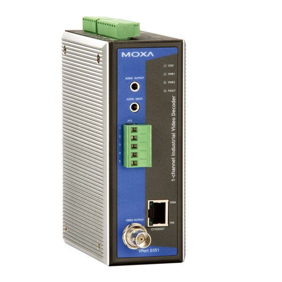
- Page 4 Panel Layout of VPort D351 VPort D351 Front Panel View 1. Grounding screw 2. RS-232 console port 3. Hardware reset button 4. 6-pin terminal block for DI 1, DI 2, power input 2 (PWR2) 5. 8-pin terminal block for Relay 1, Relay 2, power input 1 (PWR1) 6.
-
Page 5: First-Time Installation And Configuration
PC equipped with an Ethernet port. Step 1: Select the Power Source The VPort D351 can be powered by a 12 to 32 VDC power input, or an 18 to 30 VAC power input. Two power inputs are provided for redundancy. Users can check the LED status located on the front panel to see if the power inputs are connected appropriately. - Page 6 Network Environment with DHCP Server When a DHCP server is present, the IP address of the VPort D351 is assigned by the DHCP server. Use the DHCP server’s IP address table, or use the Moxa VPort and Ether Device Configurator utility to determine the IP address that was assigned by the DHCP server.
- Page 7 2. The Broadcast Search window will show a list of all switches and VPorts located on the network. The progress of the search will also be indicated. 3. When the search has ended, the Model Name, MAC address, and IP address of the EDS switches and VPorts will be listed in the Utility window.
- Page 8 Network Environment without DHCP Server If your VPort D351 is connected to a network that does not have a DHCP server, you will need to configure the IP address manually. The default IP address of the VPort D351 is 192.168.127.100 and the default subnet mask is 255.255.255.0.
-
Page 9: Mounting Dimensions (Unit=Mm)
Mounting Dimensions (unit=mm) 91.55 45.27 52.85 18.2 30.05 Din-Rail 18.2 32.1 Panel Mount Kit - 9 -... -
Page 10: Din-Rail Mounting
The aluminum DIN-Rail attachment plate should already be attached to the back panel of the VPort D351 when you take it out of the box. If you need to reattach the DIN-Rail attachment plate to the VPort D351, make sure the stiff metal spring is situated towards the top, as shown in the figures below. -
Page 11: Wiring Requirements
STEP 3: Once the screws are fixed in the wall, insert the four screw heads through the large parts of the keyhole-shaped apertures, and then slide the VPort D351 downwards, as indicated below. Tighten the four screws for added stability. -
Page 12: Wiring The Redundant Power Inputs
Wiring the Redundant Power Inputs The VPort D351 has two sets of power inputs—power input 1 and power input 2—located on the 6-pin and 8-pin terminal block connectors. Top and front views of the terminal block connectors are shown here. -
Page 13: Wiring The Digital Inputs
VPort D351’s top panel. The VPort D351’s DI 1 and DI 2 can also be used for controlling the selection of the video source. Administrators can set up this function by checking the Enable DI Change checkbox under System Configuration/ Video Source/ Video Source List. - Page 14 Auto MDI/ MDI-X (MDI) Port Pinouts (MDI-X) Port Pinouts 8-pin RJ45 Signal Signal RJ45 (8-pin) to RJ45 (8-pin) Straight-through Cable Wiring Straight-Through Cable VPort Ethernet Switch Port Port RJ45 Plug Pin 1 RJ45 RJ45 Connector Cable Wiring Connector RJ45 (8-pin) to RJ45 (8-pin) Cross-over Cable Wiring Cross-Over Cable VPort Ethernet NIC Port...
-
Page 15: Led Indicators
Step 1: Use a slender object (e.g., toothpick or paperclip) to push the reset button. Step 2: Reboot the VPort D351 and then depress the reset button. The STAT LED will blink in RED. Keep the button depressed until the STAT LED stops blinking. -
Page 16: Specifications
Specifications Video Video Decoding MPEG4, MJPEG (Auto detecting) video stream Video Input Video streams from VPort series Video Encoder or IP Camera via TCP/IP network (Not include VPort 2110, VPort 2140, VPort 2141, VPort 2310 and VPort 3310) Video Output 1 BNC connector, NTSC, or PAL Resolution Max. -
Page 17: Moxa Internet Services
EN61000-4-3 (RS), Level 3 EN61000-4-4 (EFT), Level 3 EN61000-4-5 (Surge), Level 3 EN61000-4-6 (CS), Level 3 EN61000-4-12 (Oscillatory wave immunity), Level 3 Shock IEC60068-2-27 Freefall IEC60068-2-32 Vibration IEC60068-2-6 MTBF 160,000 hours Warranty 5 years Alarm Features Automatically switch to the video source once an event is triggered on video source site Daily repeat timing schedule for DI sensors JPEG snapshots for pre/trigger/post alarm images...
Need help?
Do you have a question about the VPort D351 and is the answer not in the manual?
Questions and answers