
Subscribe to Our Youtube Channel
Related Manuals for Moxa Technologies VPort D361


Summary of Contents for Moxa Technologies VPort D361
- Page 1 Moxa VPort D361 Industrial Video Decoder User’s Manual Edition 2.0, April 2016 www.moxa.com/product © 2016 Moxa Inc. All rights reserved.
- Page 2 Moxa VPort D361 Industrial Video Decoder User’s Manual The software described in this manual is furnished under a license agreement and may be used only in accordance with the terms of that agreement. Copyright Notice © 2015 Moxa Inc. All rights reserved.
-
Page 3: Table Of Contents
Overview ............................1-2 Package Checklist ..........................1-3 Product Features ..........................1-3 Typical Application ..........................1-4 Panel Layout of the VPort D361 ......................1-5 Product Description ..........................1-6 Getting Started ..........................2-1 The Meaning of “User” and “Administrator” .................... 2-2 First-Time Installation and Configuration ....................2-2 RS-232 Console Configuration (115200, None, 8, 1, VT100) .............. -
Page 4: Introduction
Introduction The VPort D361 is a high-performance networked video decoder used to convert digital video streams to analog video signals. The following topics are covered in this chapter: Overview Package Checklist Product Features Typical Application Panel Layout of the VPort D361... -
Page 5: Overview
Up to 64 video sources can be included in the list. In addition, the two DIs located on the top panel of the VPort D361 can be used to create two control buttons for up and down video source selection. -
Page 6: Package Checklist
The CGI commands can be downloaded from Moxa’s website free of charge. Package Checklist Moxa’s VPort D361 is shipped with the items listed below. If any of these items is missing or damaged, please contact your customer service representative for assistance. •... -
Page 7: Typical Application
Supports automatically switching to a specific video source in response to an event triggered by the VPort video encoder • Supports SMTP for system or alarm message transmission NOTE Please link to Moxa’s website to download the VPort D361’s CGI commands if you need the commands for your system integration. Typical Application... -
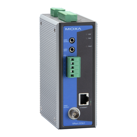
Page 8: Panel Layout Of The Vport D361
VPort D361 Introduction Panel Layout of the VPort D361 1. Grounding screw 2. RS-232 console port 3. Hardware reset button 4. 4-pin terminal block for DI 1 and DI 2 5. 8-pin terminal block for Relay 1, Relay2, power input (PWR) 6. -
Page 9: Product Description
Mini Stereo Jacks for Audio Input/Output The VPort D361 has 2 mini stereo jacks on the front panel for audio input and output. One jack is for a MIC-in/Line-in audio input connection, which can be directly connected with a microphone or an audio source from an amplifier. - Page 10 VPort D361 to create an intelligent alarm system for system operation (power failure, disconnected network). In addition, the VPort D361’s DI 1 and DI 2 can also be used for controlling the selection of the video source. The Administrator can set up this function by checking the Enable DI Change checkbox under System Configuration ...
- Page 11 Introduction RS-232 Console Port The VPort D361 has one RS-232 (10-pin RJ45) console port located on the top panel. Use either an RJ45-to-DB9 cable or RJ45-to-DB25 cable to connect the VPort D361’s console port to your PC’s COM port. You may then use a console terminal program, such as Moxa PComm Terminal Emulator, to access the VPort 351’s...
-
Page 12: Getting Started
Getting Started This chapter includes information about how to install a VPort D361 Video Decoder. The following topics are covered in this chapter: The Meaning of “User” and “Administrator” First-Time Installation and Configuration RS-232 Console Configuration (115200, None, 8, 1, VT100) ... -
Page 13: The Meaning Of "User" And "Administrator
NOTE The VPort D361 supports 12 to 32 VDC for a 12/24 VDC power input, or 18 to 30 VAC for a 24 VAC power input. This differs from the 12 to 45 VDC power input supported by Moxa’s EDS series of Ethernet switches. - Page 14 Network Environment with DHCP Server When a DHCP server is present, the IP address of the VPort D361 is assigned by the DHCP server. Use the DHCP server’s IP address table, or use the Moxa VPort and EtherDevice Configurator utility to determine the IP address that was assigned by the DHCP server.
- Page 15 Network Environment without DHCP Server If your VPort D361 is connected to a network that does not have a DHCP server, you will need to configure the IP address manually. The default IP address of the VPort D361 is 192.168.127.100 and the default subnet mask is 255.255.255.0.
- Page 16 VPort D361’s web-based manager. NOTE Once the VPort D361’s homepage opens, The Administrator can go to System Configuration System Account to set up the Administrator’s password. After that, an authentication window will open to request that...
-
Page 17: Rs-232 Console Configuration (115200, None, 8, 1, Vt100)
Connection Caution! 1. You cannot connect to the VPort D361 simultaneously by serial console and Telnet. 2. You can connect to VPort D361 simultaneously by web browser and serial console, or by web browser and Telnet. We strongly recommend that you do NOT use more than one connection method at the same time. - Page 18 VPort D361 Getting Started 1. From the Windows desktop, click Start Programs PCommLite2.5 Terminal Emulator. 2. Select Open under Port Manager to open a new connection. 3. The Communication Parameter page of the Property window opens. Select the appropriate COM port...
- Page 19 VPort D361 Getting Started 4. Click the Terminal tab, and select VT100 for Terminal Type. Click OK to continue. 5. A blank screen will appear. Press Enter to display a login message for authentication. Only the Administrator is allowed to use this console configuration. For this reason, use admin as the username and...
- Page 20 VPort D361 Getting Started 6. The VPort D361’s console Main Menu will appear. (NOTE: To modify the appearance of the PComm Terminal Emulator window, select Font… under the Edit menu, and then choose the desired formatting options.) 7. After entering the Main Menu, use the following keys to move the cursor, and to select options.
-
Page 21: Mounting The Vport D361
The aluminum DIN-Rail attachment plate should already be attached to the rear panel of the VPort D361 when you take it out of the box. If you need to reattach the DIN-Rail attachment plate to the VPort D361, make sure the stiff metal spring is situated towards the top, as shown in the figures below. -
Page 22: Wall Mounting (Optional)
VPort D361 Getting Started Wall Mounting (Optional) For some applications, you will find it convenient to mount the VPort D361 on the wall, as shown in the diagrams below. STEP 1: Remove the aluminum DIN-Rail attachment plate from the VPort 351, and then attach the wall mounting plates, as shown in the diagrams below. -
Page 23: Grounding The Vport D361
The VPort D361 has two sets of relay output—relay 1 and relay 2—located on the 8-pin terminal block connector. Each relay output consists of the 3 contacts of the terminal block on the VPort D361’s top panel. The Relay Output can be set up for: System alarm: In this case, network disconnected. -
Page 24: Wiring The Power Input
Wiring the Digital Inputs The VPort D361 has two sets of digital inputs—DI 1 and DI 2. Each DI consists of two contacts of the 6-pin terminal block connector on the VPort’s top panel. Top and front views of one of the terminal block connectors are shown here. -
Page 25: Auto Mdi/Mdi-X
VPort D361 Getting Started Auto MDI/MDI-X (MDI) Port Pinouts (MDI-X) Port Pinouts 8-pin RJ45 Signal Signal RJ45 (8-pin) to RJ45 (8-pin) Straight-through Cable Wiring RJ45 (8-pin) to RJ45 (8-pin) Cross-over Cable Wiring 2-14... -
Page 26: Accessing Vport D361'S Web-Based Manager
Accessing VPort D361’s Web-based Manager This chapter includes information about how to access VPort D361 Video Decoder for the first time. The following topics are covered in this chapter: Functions Featured on the VPort’s Web Homepage VPort’s Information ... -
Page 27: Functions Featured On The Vport's Web Homepage
VPort D361 Accessing VPort D361’s Web-based Manager Functions Featured on the VPort’s Web Homepage The homepage of the VPort’s Web-based Manager shows basic information about the VPort, camera image view, and configurations for client and server. NOTE For best viewing, use 1280 x 1024 resolution when viewing the VPort’s web homepage. -
Page 28: Video Source List
Accessing VPort D361’s Web-based Manager Video Source List A maximum of 64 video sources can be added to the VPort D361’s video source list. The following parameters can be modified: 1. Idx: video source index. 2. Source Description: customized video source description. -
Page 29: System Configuration
System Configuration After installing the hardware, the next step is to configure the VPort D361’s settings. The web-based manager can be used to access configuration options. The following topics are covered in this chapter: Using the Web-based Manager for System Configuration ... -
Page 30: Using The Web-Based Manager For System Configuration
VPort D361 System Configuration Using the Web-based Manager for System Configuration System configuration can be done remotely with Internet Explorer through the web server. Alternatively, the Administrator may type the system configuration URL, http://<IP address of Video Server>/setup/config.html, to enter the configuration page directly. Five categories of configuration are involved in configuring the system: System, Network, Video, Audio, and Alarm. -
Page 31: System
Server name Setting Description Default Max. 40 characters Give a different server name for each server to help identify the VPort D361 Video different servers. The name appears on the web homepage. Decoder... - Page 32 Domain name or IP address format of the timeserver if the DNS server is available. Don’t forget to set the Time zone for local settings. Refer to Appendix G, Time Zone Table. Account Privileges The VPort D361 only allows the Administrator to access the web-based manager. Admin password Setting...
- Page 33 VPort D361 System Configuration System Diagnosis The VPort products have a self-diagnosis function to let the Administrator get a quick view of the system and connection status. The Administrator can save this diagnosis information in a file (diagnosis.log) by clicking the Export to a File button, or sending the file by e-mail by clicking the Send a Report via Email button.
- Page 34 Step 1: Press the Browse button to select the firmware file. NOTE For the VPort D361, the firmware file extension should be .rom. Step 2: Click on the Upgrade button to upload the firmware to the VPort. Step 3: The system will start the firmware upgrade process.
-
Page 35: Network
VPort D361 System Configuration Reset to Factory Default Reset to the factory default by clicking on the OK button (as shown in the following figure). NOTE All parameters will be reset to factory defaults when you use the Factory Default function. For this reason, if you want to keep a digital copy of the current configuration, remember to export the sys_config.ini file before using... - Page 36 VPort D361 System Configuration Access Method The VPort products support the DHCP protocol, which means that the VPort can get its IP address from a DHCP server automatically when it is connected to the TCP/IP network. The Administrator should determine if it is more appropriate to use DHCP, or assign a fixed IP.
- Page 37 VPort D361 System Configuration SMTP Server and Email Account Settings The VPort not only plays the role of server, but can also connect to outside servers to send system or alarm messages. If the Administrator has set up some applications in either system information or alarm, the VPort will send out messages or snapshots once these conditions occur.
- Page 38 Enable Accessible IP List The VPort D361 uses an IP address-based filtering method to control access to the VPort. Accessible IP Settings allows you to add or remove “Legal” remote host IP addresses to prevent unauthorized access. Access to the VPort is controlled by IP address. That is, if a host’s IP address is in the accessible IP table, then the host will be allowed access to the VPort.
- Page 39 VPort D361 System Configuration Refer to the following table for more configuration examples. Allowable Hosts Input Formats Any host Disable 192.168.1.120 192.168.1.120/255.255.255.255 192.168.1.1 to 192.168.1.254 192.168.1.0/255.255.255.0 192.168.0.1 to 192.168.255.254 192.168.0.0/255.255.0.0 192.168.1.1 to 192.168.1.126 192.168.1.0/255.255.255.128 192.168.1.129 to 192.168.1.254 192.168.1.128/255.255.255.128 SNMP The VPort supports three SNMP protocols. The available protocols are SNMP V1, SNMP V2c, and SNMP V3. The...
- Page 40 VPort D361 System Configuration Configuring SNMP Settings The following figures indicate which SNMP parameters can be configured. A more detailed explanation of each parameter is given below the figure. SNMP Read/Write Settings SNMP Versions Setting Description Default V1, V2c, V3...
- Page 41 VPort D361 System Configuration Root Data Encryption Key (For SNMP V1, V2c, V3, and V3 only) Setting Description Default Enable The data encryption key must be between 8 and 30 characters No Disable No data encryption User Auth. Type (For SNMP V1, V2c, V3, and V3 only)
-
Page 42: Video Source
System Configuration Video Source Video Source List A maximum of 64 video sources can be added to the VPort D361’s video source list. The Administrator can configure the video source operation settings on this page. Video Source Switch Mode Setting... - Page 43 VPort D361 System Configuration The following description shows how to set up the video source list. a. Add Video Source Setting Description Default The video source index for video source information and 1 (1 to 64) selection. Address The domain name or IP address of the video source Blank (max.
- Page 44 VPort D361 System Configuration b. Search The Search function is used to search for video source devices on the network that are on the same domain network as the computer that you are searching from. After the search, the Administrator can select the video source device and then click Add to List to add this video source to the video source list.
-
Page 45: Video
VPort D361 System Configuration Video OSD Settings On this page, the Administrator can customize the OSD (on-screen display) information and location of the video image. Two color blocks are located in the top-right corner of the video image. Connect loss block: The connect loss block is shown in yellow to indicate the status of the video source. -
Page 46: Audio
Audio Audio Settings The VPort D361 can decode the audio being generated from the video source and can also send the audio to the video source, allowing users to enable voice communication between the video source and the VPort D361. -
Page 47: Transparent Ptz
The VPort D361 supports the transparent PTZ control function, which means the user can connect a legacy PTZ control panel to the VPort D361’s PTZ port to control the PTZ camera connected to the VPort video encoder. It is not necessary to install PTZs. -
Page 48: Alarm
The relays will not be triggered when the Override Relay 1 warning setting and Override Relay 2 warning setting boxes are checked. Un-check these 2 boxes to allow the relays to be triggered. System Alarm In addition to the LED indicators, two kinds of system alarm are provided by the VPort D361 for notifying the Administrator. 4-20... - Page 49 VPort D361 System Configuration Network Disconnected Alarm Setting Description Default Enable network Enable or disable network disconnected alarm. Disabled disconnected alarm Trigger Relay alarm Enable or disable the action in triggering Relay 1 or Relay 2 Disabled alarms. NOTE Since several alarms can be set up to trigger the VPort’s relays, the Administrator should configure these alarms carefully in case a relay message is read incorrectly.
- Page 50 Duration 00:00 Setup the time period of event alarm being activated. 00:00 Digital Input Two digital inputs are provided by the VPort D361 for linking with alarm detection devices, such as sensors. Setting Description Default Enable digit input alarm Enable or disable the digit input alarm.
- Page 51 VPort D361 System Configuration NOTE DI specifications are given in Chapter 1. Trigger Actions The Administrator can set up trigger actions for each DI, including Trigger Relay1 alarm, Trigger Relay2 alarm, Send warning message via E-mail. 4-23...
-
Page 52: How To Set Up The Alarm Trigger Function
Step 1: Set up the HTTP Event Server. Hostname If the VPort D361 uses a domain name instead of an IP address, then type the domain name in the Hostname input box. If a domain name is not being used, then leave the Hostname field blank. - Page 53 Cameraidx = 1. • Idx is the channel index of this video source in the VPort D361’s video source list. For example, if this VPort 461 is indexed in number 5 of the VPort D361’s video source list, then Idx = 5.
-
Page 54: Modus Address Table
Modus Address Table Address Unit (4 Bytes) Item name 0x0000 Vender ID 0x1393 0x0001 Unit ID 0x01 0x0002 Product Code 0x8802 0x0010 Vender Name moxa 0x0030 Product Name VPortD361 0x0050 Serial Number 0x0051 Firmware Version 0x0053 Release Date 0x0055 MAC Address 0x005A Fault Led Status 0x0080... -
Page 55: Time Zone Table
Time Zone Table The hour offsets for different time zones are shown below. You will need this information when setting the time zone in automatic date/time synchronization. GMT stands for Greenwich Mean Time, which is the global time that all time zones are measured from. (GMT-11:00) Midway Island, Samoa (GMT-10:00) - Page 56 VPort D361 Time Zone Table (GMT+03:30) Tehran (GMT+04:00) Abu Dhabi, Muscat (GMT+04:00) Baku, Tbilisi, Yerevan (GMT+04:30) Kabul (GMT+05:00) Ekaterinburg (GMT+05:00) Islamabad, Karachi, Tashkent (GMT+05:30) Chennai, Kolkata, Mumbai, New Delhi (GMT+05:45) Kathmandu (GMT+06:00) Almaty, Novosibirsk (GMT+06:00) Astana, Dhaka (GMT+06:00) Sri Jayawardenepura...
-
Page 57: Technical Specifications
Technical Specifications Video Video Decoding H.264, MJPEG (Auto detecting) video stream Video Input Video streams from the VPort series Video Encoder via TCP/IP network Video Output 1 BNC connector, NTSC, or PAL Resolution Max. 540 TVL Lines Max. 64, manually selected (by web server or digital inputs) or Video Source automatic scan with time interval Max. - Page 58 VPort D361 Technical Specifications Dimensions (W x D x H) 52.98 x 135 x 105 mm (2.09 x 5.31 x 4.13 in.) Weight 890 g Installation DIN-Rail or wall mounting (with optional WK-46 kit) Environmental Limits 0 to 60°C (32 to 140°F) Operating Temperature -40 to 75°C (-40 to 167°F) for -T model...
Need help?
Do you have a question about the VPort D361 and is the answer not in the manual?
Questions and answers