Moxa Technologies NPort DE-311 Hardware Installation Manual
Hide thumbs
Also See for NPort DE-311:
- Quick installation manual (6 pages) ,
- Tech note (5 pages) ,
- Tech note (4 pages)

Related Manuals for Moxa Technologies NPort DE-311


Summary of Contents for Moxa Technologies NPort DE-311
- Page 1 NPort DE-311 Hardware Installation Guide Fourth Edition, June 2008 www.moxa.com/product © 2008 Moxa Inc., all rights reserved. Reproduction without permission is prohibited.
- Page 2 NPort DE-311 Hardware Installation Guide The software described in this manual is furnished under a license agreement and may be used only in accordance with the terms of that agreement. Copyright Notice Copyright © 2008 Moxa Inc. All rights reserved.
-
Page 3: Table Of Contents
Table of Contents Chapter 1 Introduction....................1-1 Features ..........................1-2 Product Specifications......................1-2 Package Checklist ......................1-3 Front/Top/Rear/Bottom Panel Views.................. 1-4 Chapter 2 Overview....................2-1 LED Indicators ........................2-2 Housing ..........................2-2 DIN Rail........................2-2 Wall Mount ......................2-3 Chapter 3 Serial Installation..................3-1 DIP Switch Settings...................... -
Page 4: Chapter 1 Introduction
Introduction Chapter 1 Welcome to Moxa’s NPort Express, a compact palm-sized communications device that allows you to control RS-232/422/485 serial devices over a TCP/IP Ethernet. This chapter is an introduction to the NPort Express and includes the following sections: Features Product Specifications Package Checklist Front/Top/Rear/Bottom Panel Views... -
Page 5: Features
NPort DE-311 Hardware Installation Guide Introduction Features • 3-in-1 RS-232/422/485 serial interface • Auto-detecting 10/100 Mbps Ethernet connection • Built-in Ethernet and TCP/IP protocol • Compact size for easy integration • Supports MAC based IP configuration • Supports configuration store and copy for easy deployment •... -
Page 6: Package Checklist
NPort DE-311 Hardware Installation Guide Introduction Operation Modes Driver Mode, TCP Server, TCP Client, UDP Server/Client, Ethernet Modem, Pair Connection Management Serial console Telnet console NPort Configurator for Windows/Linux Real COM Installer for Windows Monitor Utility for Windows Firmware upgrade function supported NPort Admin for... -
Page 7: Front/Top/Rear/Bottom Panel Views
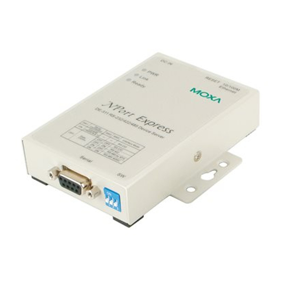
NPort DE-311 Hardware Installation Guide Introduction Front/Top/Rear/Bottom Panel Views Front Panel View 1. DB9 female serial port 2. DIP switches 3. DIN rail screw holes 1 2 3 4. Wall mount screw holes Top Panel View 5. RJ45 10/100BaseTX Ethernet port... -
Page 8: Chapter 2 Overview
Overview Chapter 2 The following topics are discussed in this chapter: LED Indicators Housing DIN Rail Wall Mount... -
Page 9: Led Indicators
NPort DE-311 Hardware Installation Guide Overview LED Indicators The NPort Express’s top panel contains five LED indicators, as described in the following table. LED Name LED Color LED Function Power is on Power is off, or power error condition exists... -
Page 10: Wall Mount
NPort DE-311 Hardware Installation Guide Overview To remove the NPort Express from the DIN rail, simply reverse Steps 2 and 3 above. Use your fingers to pull down on the B end, which should release the bracket from the rail. -
Page 11: Chapter 3 Serial Installation
Serial Installation Chapter 3 The following topics are discussed in this chapter: DIP Switch Settings DB9 Female Connector Pinouts RS-232 Pinouts RS-232 Loopback Tester RS-422/485 Pinouts RS-422 Loopback Tester Mini Adapter... -
Page 12: Dip Switch Settings
NPort DE-311 Hardware Installation Guide Serial Installation DIP Switch Settings The top panel contains a table which describes how to configure the serial port using the three DIP switches. Serial Connection Serial Interface Mode Console (19200,N,8,1) RS-232 RS-232 RS-422 Data Comm. -
Page 13: Rs-232 Loopback Tester
NPort DE-311 Hardware Installation Guide Serial Installation RS-232 Loopback Tester Signal RS-422/485 Pinouts DB9 (Female) RS-422 RS-485 RxD-(A) RxD+(B) TxD+(B) Data+(B) TxD-(A) Data-(A) CTS-(A) CTS+(B) RTS+(B) RTS-(A) RS-422 Loopback Tester Signal RxD-(A) RxD+(B) TxD+(B) TxD-(A) CTS-(A) CTS+(B) RTS+(B) RTS-(A) Mini Adapter The NPort Express DE-311 accepts devices with both male and female connectors. - Page 14 NPort DE-311 Hardware Installation Guide Serial Installation If you want to make your own DB9 male to DB9 male null-modem (or crossover) cable, the correct pinouts are as follows: - l l i n i RS-232 RS-422 RS-485 RxD-(A) RxD+(B)
-
Page 15: Chapter 4 Ethernet Installation
Ethernet Installation Chapter 4 The following topics are discussed in this chapter: Connecting to the Ethernet Port Connecting to a Hub or Switch Connecting to a PC... -
Page 16: Connecting To The Ethernet Port
NPort DE-311 Hardware Installation Guide Ethernet Installation Connecting to the Ethernet Port Connecting to a Hub or Switch For most applications, plug one end of your Ethernet cable into the NPort Express’s 10/100BaseTX port, and the other end into a hub or switch that is connected to your network. In this case, you should use a standard straight-through Ethernet cable, which is readily available from many commercial vendors. -
Page 17: Chapter 5 Power Connection
Power Connection Chapter 5 The following topics are discussed in this chapter: Connecting the Power Adapter Power Status Check... -
Page 18: Connecting The Power Adapter
NPort DE-311 Hardware Installation Guide Power Connection Connecting the Power Adapter The following steps explain how to connect the NPort Express’s power adapter: 1. Plug the power adapter’s DC plug into the DC-IN jack on the NPort Express. 2. Plug the power adapter into an electrical outlet. -
Page 19: Appendix A Telnet Console
Telnet Console Appendix A The Telnet console is used to view and modify the unit’s configuration. After installing the unit into a serial device, administrators configure their device remotely by opening a Telnet console session over the network. The following examples refer to a Telnet console session on a Windows 98 host, but the same instructions should apply to all Windows operating systems. -
Page 20: Opening The Telnet Console
NPort DE-311 Hardware Installation Guide Telnet Console Opening the Telnet Console A Telnet console session may be opened from the Windows Start menu. Select Start Run... to open a dialog box, and then enter the following: telnet [unit’s IP address] Click OK to begin the Telnet session.
Need help?
Do you have a question about the NPort DE-311 and is the answer not in the manual?
Questions and answers