H3C S5120-HI Series Installation Manual
Hide thumbs
Also See for S5120-HI Series:
- Security configuration manual (379 pages) ,
- Configuration manual (20 pages) ,
- Compliance and safety manual (20 pages)

Related Manuals for H3C S5120-HI Series


Summary of Contents for H3C S5120-HI Series
-
Page 1: Installation Guide
H3C S5120-HI Switch Series Installation Guide Hangzhou H3C Technologies Co., Ltd. http://www.h3c.com Document version: 6W102-20130630... - Page 2 SecPro, SecPoint, SecEngine, SecPath, Comware, Secware, Storware, NQA, VVG, V G, V G, PSPT, XGbus, N-Bus, TiGem, InnoVision and HUASAN are trademarks of Hangzhou H3C Technologies Co., Ltd. All other trademarks that may be mentioned in this manual are the property of their respective owners Notice The information in this document is subject to change without notice.
- Page 3 Preface H3C S5120-HI Switch Series Installation Guide describes the appearance, installation, power-on, maintenance, and troubleshooting of the S5120-HI switches. This preface includes: • Audience Conventions • About the H3C S5120-HI documentation set • Obtaining documentation • • Technical support Documentation feedback •...
- Page 4 Layer 2 forwarding and other Layer 2 features. Port numbering in examples The port numbers in this document are for illustration only and might be unavailable on your device. About the H3C S5120-HI documentation set The H3C S5120-HI documentation set includes: Documents...
-
Page 5: Obtaining Documentation
Obtaining documentation You can access the most up-to-date H3C product documentation on the World Wide Web at http://www.h3c.com. Click the links on the top navigation bar to obtain different categories of product documentation: [Technical Support &... -
Page 6: Technical Support
[Technical Support & Documents > Software Download] – Provides the documentation released with the software version. Technical support service@h3c.com http://www.h3c.com Documentation feedback You can e-mail your comments about product documentation to info@h3c.com. We appreciate your comments. -
Page 7: Table Of Contents
Contents Product overview ·························································································································································· 1 Panel views for the S5120-28SC-HI and S5120-52SC-HI ··························································································· 1 Front panel views ····················································································································································· 1 Rear panel view ························································································································································ 2 Left side panel view ·················································································································································· 3 Panel views for the S5120-34C-HI and S5120-58C-HI ······························································································· 3 ... - Page 8 Installing an interface card ··································································································································· 30 Removing an interface card ································································································································· 32 Installing/removing a CX4/SFP+ cable ·············································································································· 33 Verifying the installation ················································································································································ 33 Accessing the switch for the first time ······················································································································· 35 Setting up the configuration environment ···················································································································· 35 ...
- Page 9 Management Ethernet port ··································································································································· 59 10/100/1000Base-T Ethernet port ···················································································································· 59 SFP port ·································································································································································· 60 Combo interface ···················································································································································· 60 SFP+ port ································································································································································ 60 LEDs ················································································································································································· 60 System status LED··················································································································································· 60 Power module status LED ······································································································································ 61 ...
-
Page 10: Product Overview
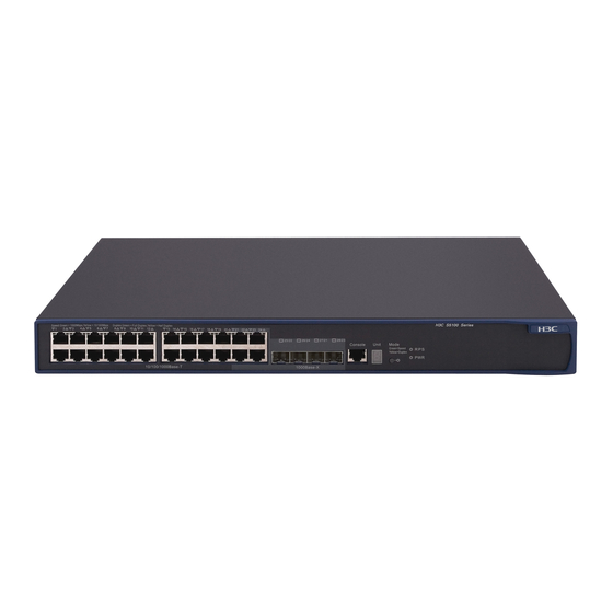
Product overview The H3C S5120-HI Switch Series includes the following models: S5120-28SC-HI • S5120-52SC-HI • S5120-34C-HI • • S5120-58C-HI Panel views for the S5120-28SC-HI and S5120-52SC-HI Front panel views Figure 1 S5120-28SC-HI front panel view (1) 10/100/1000Base-T auto-sensing Ethernet port... -
Page 11: Rear Panel View
Figure 2 S5120-52SC-HI front panel view (1) 10/100/1000Base-T auto-sensing Ethernet port (2) 10/100/1000Base-T Ethernet port LED (3) ACT LED for the management Ethernet port (4) Management Ethernet port (5) LINK LED for the management Ethernet port (6) Console port (7) Seven-segment LED (Unit) (8) Port LED mode switching button (9) System status LED (SYS) (10) SFP+ port... -
Page 12: Left Side Panel View
NOTE: Each of the S5120-28SC-HI and S5120-52SC-HI switches comes with power module slot 1 empty and • power module slot 2 covered by a filler panel. You can install one or two power modules for the switch as needed. In Figure 3, a PSR150-A power module is installed in power module slot 1. -
Page 13: Rear Panel View
(7) Port mode LED (Mode) (8) System status LED (SYS) (9) Power module 1 status LED (PWR1) (10) Power module 2 status LED (PWR2) (11) Interface card 1 status LED (SLOT1) (12) Interface card 2 status LED (SLOT2) (13) Port LED mode switching button (14) Console port (15) Management Ethernet port (Management) (16) SFP+ port... - Page 14 NOTE: Each of the S5120-34C-HI and S5120-58C-HI switches comes with power module slot 1 covered by a filler panel and power module slot 2 empty. You can install one or two power modules for the switch as needed. In Figure 7, a PSR150-A power module is installed in power module slot 2.
-
Page 15: Preparing For Installation
Preparing for installation Safety recommendations To avoid any equipment damage or bodily injury caused by improper use, read the following safety recommendations before installation. Note that the recommendations do not cover every possible hazardous condition. Before cleaning the switch, unplug all power cords from the switch. Do not clean the switch with wet •... -
Page 16: Cleanness
Lasting low relative humidity can cause washer contraction and ESD and bring problems including • loose captive screws and circuit failure. High temperature can accelerate the aging of insulation materials and significantly lower the • reliability and lifespan of the switch. For the temperature and humidity requirements, see "Appendix A Technical specifications."... -
Page 17: Installation Tools
WARNING! Do not stare into any fiber port when the switch has power. The laser light emitted from the optical fiber may hurt your eyes. Installation tools Flat-blade screwdriver • • Phillips screwdriver Long-nose pliers • Diagonal cutting pliers • •... -
Page 18: Installing The Switch
CAUTION: Keep the tamper-proof seal on a mounting screw on the chassis cover intact, and if you want to open the chassis, contact H3C for permission. Otherwise, H3C shall not be liable for any consequence. Figure 8 Hardware installation flow... -
Page 19: Installing The Switch In A 19-Inch Rack
Installing the switch in a 19-inch rack You can install an S5120-HI switch in a 19-inch rack by using one of the following methods: Use the front mounting brackets. Figure 9 shows the mounting procedure diagram. • Use the front and rear mounting brackets. Figure 10 shows the mounting procedure diagram. -
Page 20: Mounting Accessory Kit
• If you use the side grounding point, you must connect the grounding cable before you mount the chassis in the rack. • H3C recommends this installation method for data center network deployment. Mounting accessory kit S5120-28SC-HI S5120-34C-HI... - Page 21 Figure 12 Front mounting bracket (1) Hole for attaching to a rack (by using an M6 screw) (2) Hole for attaching to the switch chassis Figure 13 Rear mounting bracket and load bearing screw (1) Hole for attaching to a rack (2) Load bearing screw Figure 14 Rack mounting rail kit (1) Chassis rail...
-
Page 22: Rack-Mounting By Using Front Mounting Brackets
Rack-mounting by using front mounting brackets This mounting method is applicable to only the S5120-34C-HI and S5120-58C-HI switches. This task requires two people. To install the switch in a 19-inch rack by using the front mounting brackets: Identify the mounting positions. Wear an ESD-preventive wrist strap and make sure it makes good skin contact and is properly grounded. -
Page 23: Rack-Mounting By Using Front And Rear Mounting Brackets
The other person uses M6 screws and cage nuts (user supplied) to attach the switch to the rack. Figure 17 Mounting the switch to the rack (front mounting brackets at the port side) Figure 18 Mounting the switch to the rack (front mounting brackets at the power side) Connect the one-hole lug grounding cable to the rear grounding point (see "Connecting the rear grounding point to a grounding... - Page 24 Figure 19 Identifying the mounting and grounding positions (1) Rear grounding point (2) Load bearing screw mounting positions (choose one of the two holes) (3) Port-side front bracket mounting position Wear an ESD-preventive wrist strap and make sure it makes good skin contact and is properly grounded.
- Page 25 Attach the rear mounting brackets to the rear posts with M6 screws (user supplied), as shown Figure Figure 21 Attaching the rear mounting brackets to a rack Mount the switch chassis in the rack: One person supports the chassis bottom with one hand, holds the front part of the chassis with the other hand, and pushes the chassis into the rack gently.
-
Page 26: Rack-Mounting By Using Front Mounting Brackets And Mounting Rail Assemblies
Figure 22 Mounting the switch in the rack Connect the one-hole lug grounding cable to the rear grounding point (see "Connecting the rear grounding point to a grounding strip"). Rack-mounting by using front mounting brackets and mounting rail assemblies This mounting method is applicable to only the S5120-28SC-HI and S5120-52SC-HI switches. - Page 27 Figure 23 Identifying the mounting and grounding positions (1) Rear grounding point (2) Power-side front bracket mounting position (3) Side grounding point (4) Chassis rail mounting position Wear an ESD-preventive wrist strap and make sure it makes good skin contact and is well grounded.
- Page 28 Unpack the grounding cable and grounding screws. Align the two-hole grounding lug at one end of the cable with the grounding holes of the grounding point, insert the grounding screws into the holes, and tighten the screws with a screwdriver to attach the grounding lug to the chassis, as shown in Figure Figure 25 Attaching the grounding cable to the chassis ...
- Page 29 Verify that the slide rails have been correctly attached to the rear rack posts. Install cage nuts (user-supplied) to the front rack posts and make sure they are at the same level as the slide rails. Supporting the bottom of the switch, align the chassis rails with the slide rails on the rack posts, as shown in Figure 27.
-
Page 30: Mounting The Switch On A Workbench
Figure 28 Mounting the switch in the rack (2) If you are using the rear grounding point, connect the one-hole lug grounding cable to the rear grounding point as described in "Connecting the rear grounding point to a grounding strip."... -
Page 31: Grounding The Switch With A Grounding Strip
You can ground the switch in one of the following ways, depending on the grounding conditions available at the installation site: Grounding the switch with a grounding strip • Grounding the switch with a grounding conductor buried in the earth ground •... - Page 32 Remove the hex nut of a grounding post on the grounding strip. Cut the grounding cable as appropriate for connecting to the grounding strip. Peel 5 mm (0.20 in) of insulation sheath by using a wire stripper, and insert the bare metal part through the black insulation covering into the end of the ring terminal supplied with the switch.
-
Page 33: Grounding The Switch With A Grounding Conductor Buried In The Earth Ground
Figure 31 Connecting the grounding cable to a grounding strip (1) Hex nut (2) Ring terminal (3) Grounding post (4) Grounding strip Grounding the switch with a grounding conductor buried in the earth ground If the installation site has no grounding strips, but earth ground is available, hammer a 0.5 m (1.64 ft) or longer angle iron or steel tube into the earth ground to serve as a grounding conductor. -
Page 34: Grounding The Switch By Using The Ac Power Cord
Grounding the switch by using the AC power cord If the installation site has no grounding strips or earth ground, you ground an AC-powered switch through the PE wire of the power cord. Make sure: The power cord has a PE terminal. •... -
Page 35: Installing A Fan Tray
Installing a fan tray CAUTION: To prevent damage to the fan tray or the connectors on the backplane, insert the fan tray gently. If you encounter a hard resistance while inserting the fan tray, pull out the fan tray and insert it again. To install a fan tray: Wear an ESD-preventive wrist strap and make sure it makes good skin contact and is well grounded. -
Page 36: Installing/Removing A Power Module
Grasp the handle of the fan tray with one hand and pull the fan tray part way out the slot. Support the fan tray bottom with the other hand, and pull the fan tray slowly along the guide rails out of the slot. -
Page 37: Removing A Power Module
NOTE: If you install only one power module, install the filler panel over the empty power module slot for good ventilation. Figure 37 Installing a PSR150-A power module Removing a power module To remove a power module: Wear an ESD-preventive wrist strap and make sure it makes good skin contact and is well grounded. -
Page 38: Connecting The Psr150-D/Psr150-D1
Attach the hooks of the bail latch (shipped with the power module) into the two holes next to the power receptacle on the power module, and pull the bail latch leftwards (see Figure 38). Connect one end of the AC power cord supplied with the power module to the power receptacle on the power module (see callout 1 in Figure 39). -
Page 39: Installing/Removing An Interface Card
Connect the two wires at the other end of the power cord to a –48 VDC power source. NOTE: You can also connect the PSR150-D/PSR150-D1 to an H3C RPS800-A or RPS1600-A RPS, but you must purchase the power cord separately. - Page 40 Figure 41 Removing the filler panel over an interface card slot (1) Filler panel (2) Chassis rear panel (3) Phillips screwdriver Hold the captive screws on the front panel of the interface card, and gently push the interface card in along the slot guide rails until the interface card is in close contact with the switch chassis (see callout 1 in Figure 42.)
-
Page 41: Removing An Interface Card
Figure 43 LSP5GT8P in the chassis Figure 44 LSP5GP8P0 in the chassis Removing an interface card CAUTION: Do not touch the surface-mounted components directly with your hands. • If no new card is to be installed, install the filler panel to prevent dust and ensure good ventilation in the •... -
Page 42: Installing/Removing A Cx4/Sfp+ Cable
Figure 45 Removing an interface card Installing/removing a CX4/SFP+ cable This section assumes that you have installed a CX4/SFP+ interface card. The installation and removal procedures for the CX4 cable and the SFP+ cable are the same. This section uses the SFP+ cable as an example. The CX4 and SFP+ cables for this switch series are hot swappable. - Page 43 All interface cables are cabled indoors. If any cable is routed outdoors, verify that the socket strip with lightning protection has been properly connected.
-
Page 44: Accessing The Switch For The First Time
Accessing the switch for the first time Setting up the configuration environment The first time you access the switch you must use a console cable to connect a console terminal, for example, a PC, to the console port on the switch. Figure 46 Connecting the console port to a terminal Connecting the console cable Console cable... -
Page 45: Setting Terminal Parameters
Connect the RJ-45 connector to the console port of the switch. NOTE: Identify the mark on the console port and make sure you are connecting to the correct port. • The serial ports on PCs do not support hot swapping. If the switch has been powered on, connect the •... - Page 46 Figure 49 Setting the serial port used by the HyperTerminal connection Set Bits per second to 9600, Data bits to 8, Parity to None, Stop bits to 1, and Flow control to None, and click OK. Figure 50 Setting the serial port parameters Select File >...
- Page 47 Figure 51 HyperTerminal window On the Settings tab, set the emulation to VT100 and click OK. Figure 52 Setting terminal emulation in Switch Properties dialog box...
-
Page 48: Powering On The Switch
After the startup completes, you can access the CLI to configure the switch. For more information about the configuration commands and CLI, see H3C S5120-HI Switch Series Configuration Guides and H3C S5120-HI Switch Series Command References. -
Page 49: Setting Up An Irf Fabric
Setting up an IRF fabric You can use H3C IRF technology to connect and virtualize S5120-HI switches into a virtual switch called an "IRF fabric" for flattened network topology, and high availability, scalability, and manageability. Table 5 Model matrix for forming an IRF fabric... -
Page 50: Irf Fabric Setup Flowchart
IRF fabric setup flowchart Figure 53 IRF fabric setup flowchart Start Plan IRF fabric setup Install IRF member switches Install the grounding cable, fan tray, power modules, and power cords Power on the switches Install interface card (optional) Configure basic IRF settings Connect the physical IRF ports... -
Page 51: Planning Irf Fabric Setup
"Installing an interface card." expansion interface card. Configure basic IRF settings. See H3C S5120-HI Switch Series IRF Configuration Guide. Connect the physical IRF ports on the switches. Select appropriate cables according to physical IRF port types. Connect the physical IRF ports. -
Page 52: Planning Irf Topology And Connections
Planning IRF topology and connections You can create an IRF fabric in daisy chain topology, or more reliably, ring topology. In ring topology, the failure of one IRF link does not cause the IRF fabric to split as in daisy chain topology. Rather, the IRF fabric changes to a daisy chain topology without interrupting network services. -
Page 53: Identifying Physical Irf Ports On The Member Switches
Figure 55 IRF fabric in ring topology Identifying physical IRF ports on the member switches Identify the physical IRF ports on the member switches according to your topology and connection scheme. To set up IRF connection, you must use 10-Gigabit ports, including the two SFP+ ports on the front panel and the 10-Gigabit ports on the expansion interface card. -
Page 54: Planning The Cabling Scheme
If the IRF member switches are all in one equipment room, choose CX4/SFP+ cables or twisted pair cables. The following subsections describe several H3C recommended IRF connection schemes, and all these schemes use a ring topology. IMPORTANT: In these schemes, all physical IRF ports are located on the same side. - Page 55 Figure 56 Connecting the switches in one rack ...
-
Page 56: Configuring Basic Irf Settings
• • Execute the display irf configuration command to verify the basic IRF settings. For more information about configuring basic IRF settings, see H3C S5120-HI Switch Series IRF Configuration Guide. Connecting the physical IRF ports Use proper cables to connect the IRF member switches as planned. -
Page 57: Accessing The Irf Fabric To Verify The Configuration
Use Telnet, Web, or SNMP to access the IRF fabric from the network management station. (See H3C S5120-HI Switch Series Fundamentals Configuration Guide.) Verify that you can manage all member switches as if they were one node. -
Page 58: Maintenance And Troubleshooting
• The operating temperature of the switch is in the normal range and the power module has good • ventilation. If the problem persists, contact H3C for help. To replace a hot swappable power module, see "Installing/removing a power module."... -
Page 59: Configuration Terminal Problems
Configuration terminal problems If the configuration environment setup is correct, the configuration terminal displays booting information when the switch is powered on. If the setup is incorrect, the configuration terminal displays nothing or garbled text. No terminal display If the configuration terminal displays nothing when the switch is powered on, verify the following items: •... -
Page 60: Appendix A Technical Specifications
Rated voltage: –48 VDC to –60 VDC Max voltage: –36 VDC to –72 VDC DC-input voltage NOTE: You can use the site –48 VDC power supply or an H3C RPS800-A or RPS1600-A RPS as the DC power supply. AC: 48.2 W AC: 68 W... - Page 61 Item S5120-28SC-HI S5120-52SC-HI S5120-34C-HI S5120-58C-HI Operating humidity 5% to 95% (noncondensing) Fire resistance UL60950-1, EN60950-1, IEC60950-1, GB4943 compliance...
-
Page 62: Appendix B Frus And Compatibility Matrixes
Appendix B FRUs and compatibility matrixes This appendix describes the field replaceable units (FRUs) available for the S5120-HI switches and their compatibility. All the FRUs in this appendix are hot swappable. FRUs and compatibility matrixes FRUs S5120-28SC-HI S5120-52SC-HI S5120-34C-HI S5120-58C-HI Hot swappable power modules PSR150-A Supported... -
Page 63: Hot Swappable Fan Trays
Input voltage 12 V Maximum power consumption 19.5 W Docuementation reference H3C LSPM1FAN & LSPM1FANB Fan Assemblies Installation LSPM1FANB Fans Two 40 × 40 × 28 mm (1.57 × 1.57 × 1.1 in) fans Fan speed 18500 R.P.M Max airflow... -
Page 64: Sfp/Sfp+/Xfp Transceiver Modules And Sfp+/Cx4 Cables
SFP/SFP+/XFP transceiver modules and SFP+/CX4 cables This section describes the transceiver modules and transceiver module cables available for the H3C S5120-HI Switch Series. The transceiver modules available for this switch series are subject to change over time. For the most up-to-date list of transceiver modules, consult your H3C sales representative or technical support engineer. -
Page 65: 1000 Mbps Sfp Transceiver Modules
Central Max transmission SFP module Connector Fiber wavelength distance 9/125 μm, single SFP-FE-LH40-SM1310 1310 nm 40 km (24.86 miles) mode 9/125 μm, single SFP-FE-LH80-SM1550 1550 nm 80 km (49.71 miles) mode TX—1310 nm 9/125 μm, single SFP-FE-LX-SM1310-BIDI 15 km (9.32 miles) mode RX—1550 nm TX—1550 nm... -
Page 66: Gbps Sfp+ Transceiver Modules And Sfp+ Cables
IMPORTANT: You must use the transceiver modules coded SFP-GE-LX-SM1310-BIDI and SFP-GE-LX-SM1490-BIDI in pairs. 10 Gbps SFP+ transceiver modules and SFP+ cables Transceiver Central Connector Fiber Max transmission distance module/cable wavelength Transceiver modules 50/125 μm, SFP-XG-SX-MM850-A 850 nm 300 m (984.25 ft) multimode 62.5/125 μm, SFP-XG-LX220-MM1310... -
Page 67: Cx4 Cables
Central Max transmission XFP module Connector Fiber wavelength distance XFP-LX-SM1310 1310 nm 9/125 μm, single mode 10 km (6.21 miles) XFP-LH40-SM1550-F1 1550 nm 9/125 μm, single mode 40 km (24.86 miles) XFP-LH80-SM1550 1550 nm 9/125 μm, single mode 80 km (49.71 miles) CX4 cables CX4 cable model Connector... -
Page 68: Appendix C Ports And Leds
Appendix C Ports and LEDs Ports Console port Every S5120-HI switch has one console port. Table 9 Console port specifications Item Specification Connector type RJ-45 Compliant standard EIA/TIA-232 Transmission baud rate 9600 bps (default) to 115200 bps • Provides connection to an ASCII terminal. Services •... -
Page 69: Sfp Port
Table 11 10/100/1000Base-T Ethernet port specifications Item Specification Connector type RJ-45 • 10/100 Mbps, half/full duplex, auto MDI/MDI-X Interface attributes • 1000 Mbps, full duplex, auto MDI/MDI-X Max transmission distance 100 m (328.08 ft) Transmission medium Category-5 (or above) twisted pair cable Standards IEEE 802.3i, 802.3u, 802.3ab SFP port... -
Page 70: Power Module Status Led
Table 13 System status LED description LED mark Status Description Steady green The switch is operating properly. Flashing green (1 Hz) The switch is performing power-on self test (POST). Steady red POST has failed. Flashing yellow (1 Hz) Some ports have failed to pass POST. The switch is powered off. -
Page 71: 10/100/1000Base-T Ethernet Port Led
System status LED Seven-segment LED (Unit) status Description (SYS) status The LED displays flashing numbers. POST has failed, and the LED flashes Flashing red the ID of the failed test item. A bar rotates clockwise around the LED. Flashing green Software is loading. -
Page 72: Sfp Port Led
Port mode LED (MODE/Mode) Port LED status Description status Flashing yellow (3 Hz) POST has failed on the port. No link is present on the port. The port is operating in full duplex mode. The port LED fast Steady green flashes when the port is sending or receiving data. -
Page 73: Management Ethernet Port Leds
Table 19 SFP+ port LED description Port mode LED (MODE/Mode) SFP+ port LED status Description status The port is operating at 10 Gbps. The port LED fast flashes Steady green when the port is sending or receiving data. The port is operating at 1 Gbps. The port LED fast flashes Steady green Steady yellow when the port is sending or receiving data. -
Page 74: Interface Card Status Led
Management Port mode LED Ethernet port LED Description (Mode) status (ACT/LINK) status No link is present on the port. The port is operating in full duplex mode. The port LED fast Steady green flashes when the port is sending or receiving data. The port is operating in half duplex mode. -
Page 75: Appendix D Cooling System
Appendix D Cooling system The cooling system of an S5120-HI switch comprises the ventilation holes in the chassis, fan tray, and built-in fans of hot swappable power modules. To guarantee that this cooling system can effectively work, you must consider the site ventilation design when you plan the installation site for the switches. IMPORTANT: The chassis and the power modules use separate air aisles. -
Page 76: Index
Index A C E F G H I L M P S V Installing/removing an interface card,30 Interface cards,54 Accessing the IRF fabric to verify the configuration,48 IRF fabric setup flowchart,41 Configuration terminal problems,50 LEDs,60 Configuring basic IRF settings,47 Connecting the console cable,35 Connecting the physical IRF ports,47...
Need help?
Do you have a question about the S5120-HI Series and is the answer not in the manual?
Questions and answers