
Subscribe to Our Youtube Channel
Related Manuals for Royal Sovereign RSC-1651LS/LSH


Summary of Contents for Royal Sovereign RSC-1651LS/LSH
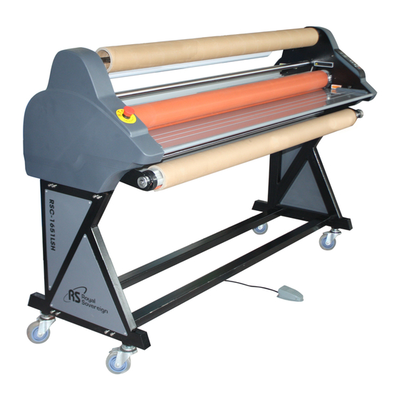
- Page 1 ROLL LAMINATOR RSC-1651LS/LSH RSC-1402HW/CW ROLL LAMINATOR Service Manual www.royalsovereign.com...
-
Page 2: Table Of Contents
Table of Contents 1. Safety Precautions ……………………………………………………………………… 2 ~ 2 2. Troubleshooting …………………………………………………………………………… 3 ~ 7 2.1) Rollers Not Heating ……………………………………………………………………………… 3 ~ 4 2.2) Rollers Over Heating ………………...…………………………………………………………… 4 ~ 5 2.3) Rollers Not Running ……………….……………………………………………………………… 5 ~ 6 2.4) No Main Power ……………………..………………………………………………………………... -
Page 3: Safety Precautions
8. Keep out of reach of children. 9 ~ 10 9. Only Royal Sovereign authorized maintenance and service technicians should make repairs. 10 ~ 11 10. Do not attempt to laminate items that exceed total recommended material thickness for the unit. -
Page 4: Troubleshooting
2. Troubleshooting 2.1 Rollers Not Heating RSC-1651LSH&RSC-1402HW/SP Only CAUSES 1. Disconnected Heater Wire. 2. Defective T/Fuse. 3. Defective Bi-metal. 4. Defective Heater Assembly. 5. Defective Main PCB. MEASURES NOTE: Below steps require you to disassemble the Right, Left, and/or Rear Covers. (Refer to the "Replacing Parts" section) Follow the below steps in order. -
Page 5: Rollers Over Heating
3. The Bi-metal is defective. a) Use the multi-tester to test the continuity on the "Bi-Metal". If it fails replace it with a new one. Figure 3 Bi-metal Figure 3 4. The heater in the roller is defective. a) Use a multi-tester to test the continuity on the "Heater Assembly". If it fails replace the Heater Assembly. -
Page 6: Rollers Not Running
2. Defective Heater Assembly a) Replace the broken Heater Assembly. Figure 2 Broken Figure 2 3. Main PCB is defective a) Replace Main PCB. 2.3) Rollers Not Running CAUSES 1. Emergency Switches are Active. 2. Laser sensor detect danger. 3. Film is Jammed on the Rollers. 4. -
Page 7: No Main Power
a) Ensure that the wire is connected properly. Figure 2 Motor wire connector Figure 2 5. Defective Main PCB. a) Replace the Main PCB. 6. Defective Main Motor. a) Replace the Main Motor. 2.4) No Main Power CAUSES 1. Main Power is Not Turned On. 2. - Page 8 a) Ensure that the control wires are connected to the Control Panel (Sub-PCB). 5. Disconnected Main Power Wire. a) Connect the Main Power wires. Figure 2 Main Power wires Figure 2 6. Defective Transformer. a) Replace the Transformer. Figure 3 Transformer Figure 3...
-
Page 9: Replacing Parts
3. Replacing Parts NOTE : Before replacing any parts, ensure that the machine is turned off and unplugged from the outlet. 3.1 Right Cover 1. Using Philips Screw Driver, loosen the screw on the Pressure Lever. Figure 1 Figure 1 2. -
Page 10: Left Cover
4. Take out four Sub-PCB screws. Figure 4 5) Repeat the steps in reverse to assemble the Right Cover. 3.2 Left Cover 1. Take out four screws on the Left Cover. 3.3 Rear Cover 1. Disassemble the Left and Right Covers. 2. -
Page 11: Sub Pcb
2. Detach the main PCB from the 4 white plastic supporters. Figure 7 Figure 7 3.5 Sub PCB 1. Follow the same steps as in the "Replacing the Right Cover" section. 2. Disassemble ten screws showing in below picture. -
Page 12: Heaters
3.6 Heaters (RSC-1651LSH&RSC-1402HW/SP Only) 1. Take off the Left and Right Covers. 2. Take out 5 screws with screw driver and disassemble the upper heater bracket showning in Figure 8 FRAME-L BRACKET Figure 8 3. Take out the screw and carelly push the heater to another side.(Figure 9) FRAME-R Figure 9 4. -
Page 13: Cross Cutter
3.7 Cross Cutter 1. Disassemble the nut from the frame-cutter. 2. Unfasten the spring from the cutter . 3. Change the cutter-knob. 3.8 Remote control PCB 1. Disconnect the plug from the frame-base. (Figure 11 & Figure 12) FRAME-BASE FRAME-BASE Figure 11 Figure 12 2.Disassmble five screws as shown in Figure 13&... -
Page 14: Adjustments
4. Adjustments 4.1 Adjusting Take-Up Shaft Speed CAUSES: 1. Main rollers and Take-Up Shaft speed is not synchronized. MEASURES: 1. Take out the Take-Up Shaft Cover by loosing three screws. Figure 1 2. Use a 11/16" (17mm) wrench to loosen (increases speed) or tighten (reduces speed) the bolt. Figure 2 Decrease Increase Figure 1... -
Page 15: Installation Of Options
5. Installation of Options Note: Below options are to be installed by an authorized RS reseller. Installation of the Front Feeder Option (Includes 2 brackets, one spindle, and mounting hardware). 1. Install the Front Feeder to the inside of the front frames using four 9/16”... -
Page 16: Parts List
6. Parts List installation mark “X”, optional mark “W” CHANGING REMARK Part No. Part Name Spec. RSC-1651LSH RSC-1651LS RSC-1402HW RSC-1402CW RSC-1401LSH RSC-1401LS P NO. DATE 013LR2190A FRAME-L(左支架) SPCC 4.5T BLACK 013LR2194A FRAME-L(左支架) SPHC 4.5T PANTONE 431C 013LR2191A FRAME-R(右支架) SPCC 4.5T BLACK 013LR2195A FRAME-R(右支架) SPHC 4.5T PANTONE 431C 011LR2003A COVER-REAR(后护盖) - Page 17 installation mark “X”, optional mark “W” CHANGING REMARK Part No. Part Name Spec. RSC-1651LSH RSC-1651LS RSC-1402HW RSC-1402CW RSC-1401LSH RSC-1401LS P NO. DATE 141LR2039A PLATE-PRESSURE,R(右压力板) SPCC 3T ZWP5(表面镀白锌) 71-1 141LR2037A PLATE-PRESSURE,L(左压力板) SPCC 3T ZWP5(表面镀白锌) 141LR3041A PLATE-PRESSURE,LAMI SPCC 4.5T ZWP5(表面镀白锌) 72-1 141LR3040A PLATE-PRESSURE,LAMI SPCC 4.5T ZWP5(表面镀白锌) 141LR3070A BRACKET-BASE SUPPORT(底板支撑) SPHC 4.5T...
- Page 18 installation mark “X”, optional mark “W” CHANGING REMARK Part No. Part Name Spec. RSC-1651LSH RSC-1651LS RSC-1402HW RSC-1402CW RSC-1401LSH RSC-1401LS P NO. DATE A22-1 21000S040A MOTOR-AC 110V 50Hz 381LR4009A WIRE-TAKE UP UL1007 AWG#20 S45C Ф53*53z 130LR4004A GEAR-MOTOR RE000600C8 RING-E Φ6 ETW-6 SWRH4/FZB 134LR4003C BUSH-PULLEY S45C MBC05040D2 SCREW-BH...
- Page 19 installation mark “X”, optional mark “W” CHANGING REMARK Part No. Part Name Spec. RSC-1651LSH RSC-1651LS RSC-1402HW RSC-1402CW RSC-1401LSH RSC-1401LS P NO. DATE...
-
Page 20: Exploded Drawings
7. Exploded Drawing FRONT FEEDER... -
Page 21: Wire Diagram
8. Wire Diagram RSC-1651LS/RSC1402CW Wire Diagram VCC_5V VCC_5V CARBON S/W VCC_5V SPEED_UP SW R104 RA101 10K x 10 U101 SPEED_DOWN SW PIC16C72 MCLR/Vpp LA101 RA102 TEMP_UP SW C106 LDQ-N51G 330R 10P 3.3/50V HEATER RC1/T1OSI TEMP_DOWN SW PWM OUT RC2/CCP1 TAK_UP RELAY SRCLK1 RC0/T1OSO/T1CKI RB0/INT... - Page 22 REV.-DATE DESCRIPTION-OF-REVISION DRA.BY CH.BY APP.BY REV.-DATE DESCRIPTION-OF-REVISION DRA.BY CH.BY APP.BY REV.-DATE DESCRIPTION-OF-REVISION DRA.BY CH.BY APP.BY REV.-DATE DESCRIPTION-OF-REVISION DRA.BY CH.BY APP.BY PART-NO DESCRIPTION MATERIAL Q'TY COLOR/FINISH REMARK PART-NO DESCRIPTION MATERIAL Q'TY COLOR/FINISH REMARK PART-NO DESCRIPTION MATERIAL Q'TY COLOR/FINISH REMARK 3rd GRADE MEDIUM DEFECT 1st GRADE FATAL DEFECT T.I.Q 4th GRADE SLIGHTLY DEFECT...
- Page 23 <connect part> 1.WIRE MAIN :above photo① →connect SUB PCB①. 5.WIRE MOTOR : above photo5 →connect DC MOTOR. 2.WIRE REMOCON:above photo2 →connect REMOCON S/W. 6.above photo's 6/7/8 wire in POWER TRANSFORMER 3.WIRE EMER:above photo3 →connect FOOT&EMER S/W. 4.WIRE POWER : above photo4 →connect FRAME-L S/W MAIN <...
- Page 24 <connect part> 1.WIRE MAIN :above photo① →connect SUB PCB①. 5.WIRE POWER : above photo6 →connect FRAME-L S/W MAIN 2.WIRE REMOCON:above photo2 →connect REMOCON S/W. 6.WIRE TAKE UP : above photo6 →connect AC MOTOR. 3.WIRE EMER:above photo3 →connect FOOT&EMER S/W. 7.above photo's 7/8/9 wire in POWER TRANSFORMER 4.WIRE UP HEATER :above photo4 →connect with 10.WIRE MOTOR : above photo10 →connect DC MOTOR.
- Page 25 BIMETAL <connect part>( only RSC-1650LSH) <connect part> 1.WIRE-UP HEATER 2 : connect above photo"B" BIMETAL and HEATER. A. WIRE-SENSOR : connect temperature sensor 2.WIRE-LOW HEATER 2 : connect above photo" A" BIMETAL and HEATER. B.WIRE-MAIN : connect the main pcb <...
- Page 26 T-FUSE <connect part> <connect part> A. WIRE T/FUSE, UP : connect with above photo A WIRE UP HEATER,Eu and HEATER.(only RSC-1650LSH)
Need help?
Do you have a question about the RSC-1651LS/LSH and is the answer not in the manual?
Questions and answers