Dell PowerEdge R430 Owner's Manual
Hide thumbs
Also See for PowerEdge R430:
- Owner's manual (188 pages) ,
- Getting started (2 pages) ,
- Owner's manual (155 pages)

Related Manuals for Dell PowerEdge R430


Summary of Contents for Dell PowerEdge R430
- Page 1 Dell PowerEdge R430 Owner's Manual Regulatory Model: E28S Series Regulatory Type: E28S001...
- Page 2 © 2016 Dell Inc. All rights reserved. This product is protected by U.S. and international copyright and intellectual property laws. Dell and the Dell logo are trademarks of Dell Inc. in the United States and/or other jurisdictions. All other marks and names mentioned herein may be trademarks of their respective companies.
-
Page 3: Table Of Contents
Contents 1 Dell PowerEdge R430 system overview............9 ...............9 Supported configurations for the PowerEdge R430 system ..........................10 Front panel features ............10 Front panel features of a 4 x 3.5-inch hard drive system ..........12 Front panel features of the 4 x 3.5-inch cabled hard drive system .......... - Page 4 System Setup details ..........................49 System BIOS ........................72 iDRAC Settings utility ..........................73 Device Settings ........................73 Dell Lifecycle Controller ....................73 Embedded system management ............................74 Boot Manager ........................74 Viewing Boot Manager ......................74 Boot Manager main menu ..............................
- Page 5 ..........................81 Inside the system ........................... 84 Cooling shroud ...................... 84 Removing the cooling shroud ......................85 Installing the cooling shroud ..........................86 System memory .................88 General memory module installation guidelines ......................88 Mode-specific guidelines ....................89 Sample memory configurations ......................95 Removing memory modules ......................
- Page 6 ........................129 iDRAC port card (optional) ..................129 Removing the optional iDRAC port card ..................131 Installing the optional iDRAC port card ........................132 SD vFlash card (optional) ..................132 Removing the optional SD vFlash card ..................133 Installing an optional SD vFlash card ....................
- Page 7 When to use the Embedded System Diagnostics ..........191 Running the Embedded System Diagnostics from Boot Manager ..... 191 Running the Embedded System Diagnostics from the Dell Lifecycle Controller ......................192 System diagnostic controls 8 Jumpers and connectors................193 ......................193 System board jumper settings .........................194...
- Page 8 System messages ........................210 Warning messages ........................210 Diagnostic messages ..........................210 Alert messages 10 Getting help..................... 211 ..........................211 Contacting Dell ......................... 211 Documentation feedback ................... 211 Accessing system information by using QRL ............212 Quick Resource Locator for the PowerEdge R430 system...
-
Page 9: Dell Poweredge R430 System Overview
Dell PowerEdge R430 system overview The Dell PowerEdge R430 systems are 2U rack servers that support up to two Intel Xeon E5-2600 v3 or Xeon E5-2600 v4 processors, up to 12 DIMMs, and ten hard drives or solid state drives (SSDs). -
Page 10: Front Panel Features
Front panel features The front panel provides access to the features available on the front of the server, such as the power button, NMI button, system identification tag, system identification button, and USB and VGA ports. The diagnostic LEDs or the LCD panel is prominently located on the front panel. The hot swappable hard drives are accessible from the front panel. - Page 11 Enables you to connect USB devices to the system iDRAC managed USB or provides access to the iDRAC Direct features. port For more information, see the Integrated Dell Remote Access Controller User’s Guide at Dell.com/idracmanuals. Use the USB 2.0 port to connect USB devices to USB port the system.
-
Page 12: Front Panel Features Of The 4 X 3.5-Inch Cabled Hard Drive System
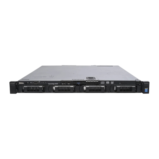
Item Indicator, Button, or Icon Description Connector Optical drive (optional) One optional slim SATA DVD-ROM drive or DVD +/-RW drive. For information about the supported optical drive, see the Technical specifications section. Front panel features of the 4 x 3.5-inch cabled hard drive system Figure 3. - Page 13 Item Indicator, Button, or Icon Description Connector • To turn the system ID on or off. To reset iDRAC, press and hold the button for more than 15 seconds. NOTE: To reset iDRAC using system ID, ensure that the system ID button is enabled in the iDRAC setup.
-
Page 14: Front Panel Features Of The 8 X 2.5 Inch Hard Drives Or Ssds System
Front panel features of the 8 x 2.5 inch hard drives or SSDs system Figure 4. Front panel features of a 8 x 2.5 inch hard drives or SSDs system Power button NMI button System identification button USB management port or iDRAC managed USB port USB port Optical drive... - Page 15 Enables you to connect USB devices to the system or iDRAC managed USB or provides access to the iDRAC Direct features. port For more information, see the Integrated Dell Remote Access Controller User’s Guide at Dell.com/idracmanuals. Use the USB 2.0 port to connect USB devices to USB port the system.
-
Page 16: Front Panel Features Of The 10 X 2.5-Inch Hard Drives Or Ssds System
Enables you to connect USB devices to the system iDRAC managed USB or provides access to the iDRAC Direct features. port For more information, see the Integrated Dell Remote Access Controller User’s Guide at Dell.com/idracmanuals. Diagnostic indicators The diagnostic indicators light up to display error status. -
Page 17: Lcd Panel
The LCD panel of your system provides system information, status, and error messages to indicate if the system is functioning correctly or if the system needs attention. For more information about error messages, see the Dell Event and Error Messages Reference Guide at Dell.com/ openmanagemanuals >OpenManage software. - Page 18 Table 5. LCD panel features Item Button Description Left Moves the cursor back in one-step increments. Select Selects the menu item highlighted by the cursor. Right Moves the cursor forward in one-step increments. During message scrolling: • Press and hold the button to increase scrolling speed. •...
-
Page 19: Back Panel Features
SEL. This enables you to match an LCD message with an SEL entry. Select Simple to view LCD error messages in a simplified user-friendly description. For more information about error messages, see the Dell Event and Error Messages Reference Guide at Dell.com/openmanagemanuals > OpenManage software. Set home Select the default information to be displayed on the Home screen. -
Page 20: Redundant Psu Back Panel Features
(optional) Use the iDRAC8 Enterprise port to remotely access iDRAC port (optional) iDRAC. For more information, see the Integrated Dell Remote Access Controller User’s Guide at Dell.com/idracmanuals. PCIe expansion card Enables you to connect two PCI Express expansion slots (2) cards. - Page 21 Item Indicator, Button, or Icon Description Connector video/VGA port, see the Technical specifications section. Use the Ethernet port to connect Local Area Ethernet port 2 Networks (LANs) to the system. For more information about the supported Ethernet ports, see the Technical specifications section. Use the USB 2.0 port to connect USB devices to USB port the system.
-
Page 22: Cabled Psu Back Panel Features
(optional) Use the iDRAC8 Enterprise port to remotely access iDRAC port (optional) iDRAC. For more information, see the Integrated Dell Remote Access Controller User’s Guide at Dell.com/idracmanuals. PCIe expansion card Enables you to connect two PCI Express expansion slots (2) cards. -
Page 23: Diagnostic Indicators
Item Indicator, Button, or Icon Description Connector video/VGA port, see the Technical specifications section. Use the Ethernet port to connect Local Area Ethernet port 2 Networks (LANs) to the system. For more information about the supported Ethernet ports, see the Technical specifications section. Use the USB 2.0 port to connect USB devices to USB port the system. - Page 24 Check the System Event Log or system messages for the specific issue. For more • When the system is turned on. information about error messages, see the Dell Event and Error Messages Reference • When the system is in standby. Guide at Dell.com/openmanagemanuals > •...
-
Page 25: Hard Drive Indicator Codes
Related Links Getting help Expansion card installation guidelines Hard drive indicator codes Each hard drive carrier has an activity indicator and a status indicator. The indicators provide information about the current status of the hard drive. The activity LED indicates whether hard drive is currently in use or not. -
Page 26: Usata Ssd Indicator Codes
Drive-status indicator pattern (RAID only) Condition Steady green Drive online Flashes green for three seconds, amber for Rebuild stopped three seconds, and then turns off after six seconds uSATA SSD indicator codes Figure 10. uSATA SSD indicators uSATA SSD activity indicator uSATA SSD status indicator uSATA SSD NOTE: If the SSD is in the Advanced Host Controller Interface (AHCI) mode, the status indicator (on... -
Page 27: Nic Indicator Codes
NIC indicator codes Each NIC on the back panel has an indicator that provides information about the network activity and link status. The activity LED indicates whether the NIC is currently connected or not. The link LED indicates the speed of the connected network. Figure 11. -
Page 28: Idrac Direct Led Indicator Codes
Figure 12. Internal dual SD module (IDSDM) LED status indicator (2) The following table describes the IDSDM indicator codes: Table 12. IDSDM indicator codes Convention IDSDM indicator code Description Green Indicates that the card is online. Flashing green Indicates rebuild or activity. Flashing amber Indicates card mismatch or that the card has failed. - Page 29 Figure 13. iDRAC Direct LED indicator iDRAC Direct status indicator The iDRAC Direct LED indicator table describes iDRAC Direct activity when configuring iDRAC Direct by using the management port (USB XML Import). Table 13. iDRAC Direct LED indicators Convention iDRAC Direct Condition LED indicator pattern...
-
Page 30: Indicator Codes For Redundant Power Supply Unit
CAUTION: Do not disconnect the power cord or unplug the PSU when updating firmware. If firmware update is interrupted, the PSUs will not function. You must roll back the PSU firmware by using Dell Lifecycle Controller. For more information, see Dell Lifecycle Controller User’s Guide at Dell.com/idracmanuals. -
Page 31: Non-Redundant Power Supply Unit Indicator Codes
Convention Power Indicator Condition Pattern NOTE: Mixing PSUs from previous generations of Dell PowerEdge servers can result in a PSU mismatch condition or failure to turn the system on. Flashing amber Indicates a problem in the PSU. CAUTION: When correcting a PSU mismatch, replace only the PSU with the flashing indicator. -
Page 32: Locating Service Tag Of Your System
Code and Service Tag are found on the front of the system by pulling out the information tag. Alternatively, the information may be on a sticker on the chassis of the system. This information is used by Dell to route support calls to the appropriate personnel. -
Page 33: Documentation Resources
For information about iDRAC features, Dell.com/idracmanuals system configuring and logging in to iDRAC, and managing your system remotely, see the Integrated Dell Remote Access Controller User's Guide. For information about installing the Dell.com/operatingsystemmanuals operating system, see the operating system documentation. - Page 34 OpenManage Essentials, see the Dell OpenManage Essentials User’s Guide. For information about installing and Dell.com/DSET using Dell System E-Support Tool (DSET), see the Dell System E-Support Tool (DSET) User's Guide. For information about installing and Dell.com/asmdocs using Active System Manager (ASM), see the Active System Manager User’s...
- Page 35 Task Document Location by the system firmware and agents that monitor system components, see the Dell Event and Error Messages Reference Guide.
-
Page 36: Technical Specifications
The technical and environmental specifications of your system are outlined in this section. Chassis dimensions This section describes the physical dimensions of the system. Figure 16. Chassis dimensions of the PowerEdge R430 system Table 18. Dimensions of the Dell PowerEdge R430 system Z (with... -
Page 37: Processor Specifications
PowerEdge R430 19.9 kg (43.87 lb) Processor specifications The PowerEdge R430 system supports up to two Intel Xeon E5-2600 v3 or Intel Xeon E5-2600 v4 product family processors. PSU specifications The PowerEdge R430 system supports up to two AC redundant power supply units (PSUs) and a single AC cabled PSU. -
Page 38: Memory Specifications
Drive specifications Hard drives The PowerEdge R430 system supports SAS, SATA, Nearline SAS hard drives and Solid State Drives (SSDs). Table 23. Supported hard drive and SSD options for the PowerEdge R430 system Up to four 3.5-inch cabled hard drives, or Up to four 3.5-inch hot-swappable SAS, SATA, or... -
Page 39: Ports And Connectors Specifications
The PowerEdge R430 system supports four 10/100/1000 Mbps Network Interface Controller (NIC) ports on the back panel. Serial connector The serial connector connects a serial device to the system. The PowerEdge R430 system supports one serial connector on the back panel, which is a 9-pin connector, Data Terminal Equipment (DTE), 16550- compliant. -
Page 40: Environmental Specifications
60, 75 8, 16, 32 1440 x 900 8, 16, 32 Environmental specifications NOTE: For additional information about environmental measurements for specific system configurations, see Dell.com/environmental_datasheets. Table 26. Temperature specifications Temperature Specifications Storage –40°C to 65°C (–40°F to 149°F) Continuous operation (for altitude less than 10°C to 35°C (50°F to 95°F) with no direct sunlight on the... -
Page 41: Particulate And Gaseous Contamination Specifications
Table 29. Maximum shock specifications Maximum shock Specifications Operating Six consecutively executed shock pulses in the positive and negative x, y, and z axes of 40 G for up to 2.3 ms. Storage Six consecutively executed shock pulses in the positive and negative x, y, and z axes (one pulse on each side of the system) of 71 G for up to 2 ms. -
Page 42: Expanded Operating Temperature
Particulate contamination Specifications NOTE: This condition applies to data center and non-data center environments. • Air must be free of corrosive dust. Corrosive dust • Residual dust present in the air must have a deliquescent point less than 60% relative humidity. NOTE: This condition applies to data center and non-data center environments. -
Page 43: Expanded Operating Temperature Restrictions
Do not perform a cold startup below 5°C. • Allow processor performance degrade. • Non-redundant power supplies are not supported. • Non Dell qualified peripheral cards and/or peripheral cards are not supported. • Maximum altitude for the operating temperature must be 3050 m (10,000 ft). -
Page 44: Initial System Setup And Configuration
Turn on the attached peripherals. iDRAC configuration The Integrated Dell Remote Access Controller (iDRAC) is designed to make system administrators more productive and improve the overall availability of Dell systems. iDRAC alerts administrators to system issues, helps them perform remote system management, and reduces the need for physical access to the system. -
Page 45: Options To Install The Operating System
Smart Card. NOTE: You must have iDRAC credentials to log in to iDRAC. For more information about logging in to iDRAC and iDRAC licenses, see the Integrated Dell Remote Access Controller User's Guide at Dell.com/idracmanuals. Options to install the operating system... - Page 46 Using Dell OpenManage Deployment Toolkit (DTK) Dell.com/openmanagemanuals Downloading the drivers and firmware Dell recommends that you download and install the latest BIOS, drivers, and systems management firmware on your system. Prerequisites Ensure that you clear the web browser cache before downloading the drivers and firmware.
-
Page 47: Pre-Operating System Management Applications
Options to manage the pre-operating system applications Your system has the following options to manage the pre-operating system applications: • System Setup • Boot Manager • Dell Lifecycle Controller • Preboot Execution Environment (PXE) Related Links System Setup Boot Manager Dell Lifecycle Controller PXE boot... -
Page 48: Viewing System Setup
UEFI (Unified Extensible Firmware Interface). You can enable or disable various iDRAC parameters by using the iDRAC settings utility. For more information about this utility, see Integrated Dell Remote Access Controller User’s Guide at Dell.com/idracmanuals. Device Settings Enables you to configure device settings. -
Page 49: System Bios
System BIOS You can use the System BIOS screen to edit specific functions such as boot order, system password, setup password, set the RAID mode, and enable or disable USB ports. Related Links System BIOS Settings details Boot Settings Network Settings System Information Memory Settings Processor Settings... - Page 50 Option Description Network Settings Specifies options to change the network settings. Integrated Specifies options to manage integrated device controllers and ports and specify Devices related features and options. Serial Specifies options to manage the serial ports and specify related features and Communication options.
- Page 51 Option Description Boot Mode Enables you to set the boot mode of the system. CAUTION: Switching the boot mode may prevent the system from booting if the operating system is not installed in the same boot mode. If the operating system supports UEFI, you can set this option to UEFI. Setting this field to BIOS allows compatibility with non-UEFI operating systems.
- Page 52 NOTE: Operating systems must be UEFI-compatible to be installed from the UEFI boot mode. DOS and 32-bit operating systems do not support UEFI and can only be installed from the BIOS boot mode. NOTE: For the latest information about supported operating systems, go to Dell.com/ossupport. Related Links Boot Settings...
- Page 53 On the System Setup Main Menu screen, click System BIOS. On the System BIOS screen, click Network Settings. Related Links Network Settings Network Settings screen details Network Settings screen details The Network Settings screen details are explained as follows: Option Description PXE Device n (n = Enables or disables the device.
- Page 54 UEFI iSCSI Settings details The UEFI ISCSI Settings screen details are explained as follows: Option Description ISCSI Initiator Specifies the name of the iSCSI initiator (iqn format). Name ISCSI Device n (n = Enables or disables the iSCSI device. When disabled, a UEFI boot option is created 1 to 4) for the iSCSI device automatically.
- Page 55 Option Description TPM Security NOTE: The TPM menu is available only when the TPM module is installed. Enables you to control the reporting mode of the TPM. The TPM Security option is set to Off by default. You can only modify the TPM Status, TPM Activation, and Intel TXT fields if the TPM Status field is set to either On with Pre-boot Measurements or On without Pre-boot Measurements.
- Page 56 Secure Boot Custom Policy Settings Secure Boot Custom Policy Settings is displayed only when Secure Boot Policy is set to Custom. Viewing Secure Boot Custom Policy Settings To view the Secure Boot Custom Policy Settings screen, perform the following steps: Turn on, or restart your system.
- Page 57 Reenter the system password, and click OK. In the Setup Password field, type your setup password and press Enter or Tab. A message prompts you to reenter the setup password. Reenter the setup password, and click OK. Press Esc to return to the System BIOS screen. Press Esc again. A message prompts you to save the changes.
- Page 58 Operating with a setup password enabled If Setup Password is set to Enabled, type the correct setup password before modifying the system setup options. If you do not type the correct password in three attempts, the system displays the following message: Invalid Password! Number of unsuccessful password attempts: <x>...
- Page 59 Option Description System BIOS Specifies the BIOS version installed on the system. Version System Specifies the current version of the Management Engine firmware. Management Engine Version System Service Specifies the system Service Tag. System Specifies the name of the system manufacturer. Manufacturer System Specifies the contact information of the system manufacturer.
- Page 60 Operating Mode Advanced ECC Mode, Mirror Mode, Spare Mode, Spare with Advanced ECC Mode, Dell Fault Resilient Mode and Dell NUMA Fault Resilient Mode. This option is set to Optimizer Mode by default. NOTE: The Memory Operating Mode option can have different default and available options based on the memory configuration of your system.
- Page 61 Viewing Processor Settings To view the Processor Settings screen, perform the following steps: Turn on, or restart your system. Press F2 immediately after you see the following message: F2 = System Setup NOTE: If your operating system begins to load before you press F2, wait for the system to finish booting, and then restart your system and try again.
- Page 62 NOTE: This option is only available on certain stock keeping units (SKUs) of the processors. X2Apic Mode Enables or disables the X2Apic mode. Dell Controlled Controls the turbo engagement. Enable this option only when System Profile is set Turbo to Performance.
- Page 63 Related Links SATA Settings details System BIOS Viewing SATA Settings Viewing SATA Settings To view the SATA Settings screen, perform the following steps: Turn on, or restart your system. Press F2 immediately after you see the following message: F2 = System Setup NOTE: If your operating system begins to load before you press F2, wait for the system to finish booting, and then restart your system and try again.
- Page 64 Option Description Option Description Model Specifies the drive model of the selected device. Drive Type Specifies the type of drive attached to the SATA port. Capacity Specifies the total capacity of the hard drive. This field is undefined for removable media devices such as optical drives.
- Page 65 Option Description Port F Sets the drive type of the selected device. For Embedded SATA settings in ATA mode, set this field to Auto to enable BIOS support. Set it to OFF to turn off BIOS support. For AHCI or RAID mode, BIOS support is always enabled. Option Description Model...
- Page 66 Option Description Option Description Capacity Specifies the total capacity of the hard drive. This field is undefined for removable media devices such as optical drives. Port J Sets the drive type of the selected device. For Embedded SATA settings in ATA mode, set this field to Auto to enable BIOS support.
- Page 67 Option Description USB 3.0 Setting Enables or disables the USB 3.0 support. Enable this option only if your operating system supports USB 3.0. If you disable this option, devices operate at USB 2.0 speed. USB 3.0 is enabled by default. User Accessible Enables or disables the USB ports.
- Page 68 Serial Communication You can use the Serial Communication screen to view the properties of the serial communication port. Related Links Serial Communication details System BIOS Viewing Serial Communication Viewing Serial Communication To view the Serial Communication screen, perform the following steps: Turn on, or restart your system.
- Page 69 Option Description NOTE: Every time the system boots, the BIOS syncs the serial MUX setting saved in iDRAC. The serial MUX setting can independently be changed in iDRAC. Loading the BIOS default settings from within the BIOS setup utility may not always revert this setting to the default setting of Serial Device 1. Failsafe Baud Rate Specifies the failsafe baud rate for console redirection.
- Page 70 Option Description Performance Per Watt Optimized (DAPC) by default. DAPC is Dell Active Power Controller. NOTE: All the parameters on the system profile setting screen are available only when the System Profile option is set to Custom. CPU Power Sets the CPU power management. This option is set to System DBPM (DAPC) by Management default.
- Page 71 Option Description NOTE: This option can be disabled only if the C States option in the Custom mode is set to disabled. NOTE: When C States is set to Enabled in the Custom mode, changing the Monitor/Mwait setting does not impact the system power or performance. Related Links System Profile Settings Viewing System Profile Settings...
-
Page 72: Idrac Settings Utility
NOTE: Accessing some of the features on the iDRAC settings utility needs the iDRAC Enterprise License upgrade. For more information about using iDRAC, see Dell Integrated Dell Remote Access Controller User's Guide at Dell.com/idracmanuals. Related Links... -
Page 73: Device Settings
The Dell Lifecycle Controller can be started during the boot sequence and can function independently of the operating system. NOTE: Certain platform configurations may not support the full set of features provided by the Dell Lifecycle Controller. For more information about setting up the Dell Lifecycle Controller, configuring hardware and firmware, and deploying the operating system, see the Dell Lifecycle Controller documentation at Dell.com/... -
Page 74: Boot Manager
Launch System Enables you to access System Setup. Setup Launch Lifecycle Exits the Boot Manager and invokes the Dell Lifecycle Controller program. Controller System Utilities Enables you to launch System Utilities menu such as System Diagnostics and UEFI shell. -
Page 75: Pxe Boot
• Launch Diagnostics • BIOS Update File Explorer • Reboot System Related Links Boot Manager PXE boot The Preboot Execution Environment (PXE) is an industry standard client or interface that allows networked computers that are not yet loaded with an operating system to be configured and booted remotely by an administrator. -
Page 76: Installing And Removing System Components
Damage due to servicing that is not authorized by Dell is not covered by your warranty. Read and follow the safety instructions that are shipped with your product. -
Page 77: After Working Inside Your System
Install the system cover. If applicable, install the system into the rack. For more information, see the Rack Installation placemat at Dell.com/poweredgemanuals. If removed, install the optional front bezel. Reconnect the peripherals and connect the system to the electrical outlet. -
Page 78: Installing The Optional Front Bezel
Figure 17. Removing the optional front bezel bezel lock front bezel Installing the optional front bezel Prerequisites Follow the safety guidelines listed in the Safety instructions section. Steps Locate and remove the bezel key. NOTE: The bezel key is attached to the back of the bezel. Hook the right end of the bezel onto the chassis. -
Page 79: System Cover
Figure 18. Installing the optional front bezel bezel lock front bezel System cover The system cover protects the components inside the system and helps in maintaining air flow inside the system. Removing the system cover actuates the intrusion switch which aids in maintaining system security. -
Page 80: Installing The System Cover
Figure 19. Removing the system cover system cover latch latch release lock Next steps Install the system cover. Related Links Safety instructions Removing the optional front bezel Installing the system cover Installing the system cover Prerequisites Follow the safety guidelines listed in the Safety instructions section. Ensure that all internal cables are connected and placed out of the way and no tools or extra parts are left inside the system. -
Page 81: Inside The System
Damage due to servicing that is not authorized by Dell is not covered by your warranty. Read and follow the safety instructions that are shipped with your product. - Page 82 Figure 21. Inside the system—with a cabled power supply control panel cable routing latch power supply unit expansion-card riser connector (2) memory-module socket (B3, B4) processor 2 memory-module socket (B1, B2) memory-module socket (A1, A5, A2, A6) processor 1 memory-module socket (A3, A7, A4, A8) cooling fan (5) optical drive (optional)
- Page 83 Figure 22. Inside the system—with redundant power supplies control panel hard drive/SSD backplane cable routing latch power interposer board power supply units (2) PCIe expansion card riser (optional) memory-module socket (B3, B4) processor 2 memory-module socket (B1, B2) memory-module socket (A1, A5, A2, A6) processor 1 memory-module socket (A3, A7, A4, A8) cooling fan (6)
-
Page 84: Cooling Shroud
Damage due to servicing that is not authorized by Dell is not covered by your warranty. Read and follow the safety instructions that are shipped with your product. -
Page 85: Installing The Cooling Shroud
Damage due to servicing that is not authorized by Dell is not covered by your warranty. Read and follow the safety instructions that are shipped with your product. -
Page 86: System Memory
Figure 24. Installing the cooling shroud cooling shroud intrusion switch intrusion switch connector on the system guide on the cooling shroud board guide pin Next steps Follow the procedure listed in the After working inside your system section. Related Links Safety instructions Before working inside your system After working inside your system... - Page 87 NOTE: DIMMs in sockets A1 to A8 are assigned to processor 1 and DIMMs in sockets B1 to B4 are assigned to processor 2. Figure 25. System memory board Memory channels are organized as follows: Processor 1 channel 0: memory sockets A1 and A5 channel 1: memory sockets A2 and A6 channel 2: memory sockets A3 and A7 channel 3: memory sockets A4 and A8...
-
Page 88: General Memory Module Installation Guidelines
The following table shows the memory populations and operating frequencies for the supported configurations. Table 37. Supported configurations DIMM type DIMMs Voltage Operating frequency Maximum DIMM rank/ populated/ (in MT/s) channel channel RDIMM 1.2 V 2400, 2133, 1866 Dual rank or single rank General memory module installation guidelines NOTE: Memory configurations that fail to observe these guidelines can prevent your system from booting, stop responding during memory configuration, or operating with reduced memory. -
Page 89: Sample Memory Configurations
Advanced Error Correction Code (lockstep) Advanced Error Correction Code (ECC) mode extends SDDC from x4 DRAM based DIMMs to both x4 and x8 DRAMs. This protects against single DRAM chip failures during normal operation. The installation guidelines for memory modules are as follows: •... - Page 90 System DIMM Size Number of DIMM Rank, DIMM Slot Population Capacity (in (in GB) DIMMs Organization, and Frequency 1R, x8, 2400 MT/s, 1R, x8, 2133 MT/s, 1R, x8, 1866 MT/s 1R, x8, 2400 MT/s, A1, A2, A3, A4 1R, x8, 2133 MT/s, 1R, x8, 1866 MT/s 2R, x8, 2400 MT/s, A1, A2...
- Page 91 System DIMM Size Number of DIMM Rank, DIMM Slot Population Capacity (in (in GB) DIMMs Organization, and Frequency 1R, x8, 2400 MT/s, 1R, x8, 2133 MT/s, 1R, x8, 1866 MT/s 2R, x8, 2400 MT/s, A1, A2, A3, A4, A5, A6 2R, x8, 2133 MT/s, 2R, x8, 1866 MT/s 2R, x8, 2400 MT/s,...
- Page 92 System DIMM Size Number of DIMM Rank, DIMM Slot Population Capacity (in (in GB) DIMMs Organization, and Frequency 2R, x8, 2400 MT/s, A1, A2, A3, A4 2R, x4, 2133 MT/s, 2R, x4, 1866 MT/s, 2R, x4, 2400 MT/s A1, A2, A3, A4, A5, A6 2R, x4, 2133 MT/s 2R, x4, 1866 MT/s 2R, x4, 2400 MT/s...
- Page 93 System DIMM Size (in Number of DIMM Rank, DIMM Slot Population Capacity (in DIMMs Organization, and Frequency 2R, x8, 2400 MT/s, A1, A2, B1, B2 2R, x8, 2133 MT/s, 2R, x8, 1866 MT/s 2R, x8, 2400 MT/s, A1, B1 2R, x8, 2133 MT/s, 2R, x8, 1866 MT/s 2R, x8, 2400 MT/s, A1, A2, A3, A4, A5, A6, A7, A8,...
- Page 94 System DIMM Size (in Number of DIMM Rank, DIMM Slot Population Capacity (in DIMMs Organization, and Frequency 2R, x4, 2400 MT/s, A1, A2, A3, A4, B1, B2, B3, B4 2R, x4, 2133 MT/s, 2R, x4, 1866 MT/s 2R, x4, 2400 MT/s, A1, A2, B1, B2 2R, x4, 2133 MT/s, 2R, x4, 1866 MT/s...
-
Page 95: Removing Memory Modules
Damage due to servicing that is not authorized by Dell is not covered by your warranty. Read and follow the safety instructions that are shipped with your product. -
Page 96: Installing Memory Modules
Figure 26. Removing the memory module memory module memory module socket memory module socket ejector (2) Next steps Install the memory module. NOTE: If you are removing the memory module permanently, install a memory module blank. Install the cooling shroud. Follow the procedure listed in the After working inside your system section. - Page 97 Damage due to servicing that is not authorized by Dell is not covered by your warranty. Read and follow the safety instructions that are shipped with your product.
-
Page 98: Hard Drives
memory module socket ejector (2) Next steps Install the cooling shroud. Follow the procedure listed in the After working inside your system section. Press F2 to enter System Setup, and check the System Memory setting. The system should have already changed the value to reflect the installed memory. If the value is incorrect, one or more of the memory modules may not be installed properly. -
Page 99: Removing A 2.5-Inch Hard Drive Blank
Damage due to servicing that is not authorized by Dell is not covered by your warranty. Read and follow the safety instructions that are shipped with your product. -
Page 100: Removing A 3.5-Inch Hard Drive Blank
Damage due to servicing that is not authorized by Dell is not covered by your warranty. Read and follow the safety instructions that came with the product. -
Page 101: Installing A 3.5-Inch Hard Drive Blank
Figure 30. Removing a 3.5-inch hard drive blank hard drive blank release button Next steps If applicable, install the front bezel. Related Links Safety instructions Removing the optional front bezel Installing the optional front bezel Installing a 3.5-inch hard drive blank Prerequisites Follow the safety guidelines listed in the Safety instructions section. -
Page 102: Removing A 3.5-Inch Cabled Hard Drive Carrier
Damage due to servicing that is not authorized by Dell is not covered by your warranty. Read and follow the safety instructions that are shipped with your product. -
Page 103: Installing A 3.5-Inch Cabled Hard Drive Carrier
Damage due to servicing that is not authorized by Dell is not covered by your warranty. Read and follow the safety instructions that are shipped with your product. -
Page 104: Removing A Hot Swappable Hard Drive Carrier
Damage due to servicing that is not authorized by Dell is not covered by your warranty. Read and follow the safety instructions that came with the product. - Page 105 Using the management software, prepare the hard drive for removal. For more information, see the documentation for the storage controller. If the hard drive is online, the green activity or fault indicator flashes when the hard drive is turned off. You can remove the hard drive when the hard drive indicators turn off. CAUTION: To prevent data loss, ensure that your operating system supports hot-swap drive installation.
-
Page 106: Installing A Hot Swappable Hard Drive Carrier
Damage due to servicing that is not authorized by Dell is not covered by your warranty. Read and follow the safety instructions that are shipped with your product. -
Page 107: Removing A 3.5-Inch Hot Swappable Hard Drive Adapter From A 3.5-Inch Hot Swappable Hard Drive Carrier
Damage due to servicing that is not authorized by Dell is not covered by your warranty. Read and follow the safety instructions that are shipped with your product. -
Page 108: Installing A 3.5-Inch Hard Drive Adapter Into A Hot Swap Hard Drive Carrier
Damage due to servicing that is not authorized by Dell is not covered by your warranty. Read and follow the safety instructions that are shipped with your product. -
Page 109: Removing A 2.5-Inch Hard Drive From A 3.5-Inch Hard Drive Adapter
Damage due to servicing that is not authorized by Dell is not covered by your warranty. Read and follow the safety instructions that came with the product. -
Page 110: Installing A 2.5-Inch Hard Drive Into A 3.5-Inch Hard Drive Adapter
Damage due to servicing that is not authorized by Dell is not covered by your warranty. Read and follow the safety instructions that are shipped with your product. -
Page 111: Removing A Hard Drive From A Hard Drive Carrier
Figure 39. Installing a 2.5-inch hard drive into a 3.5-inch hard drive adapter 3.5-inch hard drive adapter screw (2) 2.5-inch hard drive Next steps Install the 3.5-inch adapter into the 3.5-inch hard drive carrier. Related Links Safety instructions Removing a 3.5-inch hot swappable hard drive adapter from a 3.5-inch hot swappable hard drive carrier Installing a 3.5-inch hard drive adapter into a hot swap hard drive carrier Removing a hard drive from a hard drive carrier... -
Page 112: Installing A Hard Drive Into A Hard Drive Carrier
Damage due to servicing that is not authorized by Dell is not covered by your warranty. Read and follow the safety instructions that are shipped with your product. -
Page 113: Optical Drive (Optional)
Damage due to servicing that is not authorized by Dell is not covered by your warranty. Read and follow the safety instructions that are shipped with your product. -
Page 114: Installing The Optional Ultra Slim Optical Drive
Damage due to servicing that is not authorized by Dell is not covered by your warranty. Read and follow the safety instructions that are shipped with your product. -
Page 115: Removing The Standard Optical Drive
Damage due to servicing that is not authorized by Dell is not covered by your warranty. Read and follow the safety instructions that are shipped with your product. -
Page 116: Installing The Standard Optical Drive
Damage due to servicing that is not authorized by Dell is not covered by your warranty. Read and follow the safety instructions that are shipped with your product. - Page 117 Follow the safety guidelines listed in the Safety instructions section. Follow the procedure listed in the Before working inside your system section. Steps Align the two notches on the metal standoffs with the slots on the side of the optical drive. Slide the optical drive into the notches until it is seated firmly and the release latch snaps into place.
-
Page 118: Cooling Fans
Damage due to servicing that is not authorized by Dell is not covered by your warranty. Read and follow the safety instructions that are shipped with your product. -
Page 119: Installing A Cooling Fan
Damage due to servicing that is not authorized by Dell is not covered by your warranty. Read and follow the safety instructions that are shipped with your product. - Page 120 Follow the procedure listed in the Before working inside your system section. Remove the cooling shroud. If installed, remove the cooling fan blank. Steps Lower the fan into the cooling fan bracket. Connect the power cable to the power cable connector on the system board. Figure 47.
-
Page 121: Internal Usb Memory Key (Optional)
Damage due to servicing that is not authorized by Dell is not covered by your warranty. Read and follow the safety instructions that are shipped with your product. -
Page 122: Expansion Cards And Expansion Card Riser
Insert the replacement USB memory key into the USB port. Figure 49. Installing the internal USB memory key USB memory key USB port Next steps Follow the procedure listed in the After working inside your system section. While booting, press F2 to enter System Setup and verify that the system detects the USB memory key. - Page 123 Table 40. Expansion card slots available on the expansion-card riser Expansion- PCIe slot on the Processor Height Length Link Slot width card riser expansion-card connection width riser PCIE_G3_X16 Processor 1 Half Height Half Length Processor 1 Half Height Half Length PCIE_G3_X8 Processor 1 Full Height...
-
Page 124: Removing The Expansion Card Riser
Damage due to servicing that is not authorized by Dell is not covered by your warranty. Read and follow the safety instructions that are shipped with your product. -
Page 125: Installing The Expansion Card Riser
Damage due to servicing that is not authorized by Dell is not covered by your warranty. Read and follow the safety instructions that are shipped with your product. -
Page 126: Removing An Expansion Card
Damage due to servicing that is not authorized by Dell is not covered by your warranty. Read and follow the safety instructions that are shipped with your product. - Page 127 Disconnect any cables connected to the expansion card or expansion card riser. If installed, remove the expansion card riser. Steps Hold the expansion card by its edges and remove it from the expansion card riser connector. If you are removing the card permanently, install a filler bracket in the empty expansion card slot and close the expansion card latch.
-
Page 128: Installing An Expansion Card
Damage due to servicing that is not authorized by Dell is not covered by your warranty. Read and follow the safety instructions that are shipped with your product. -
Page 129: Idrac Port Card (Optional)
Damage due to servicing that is not authorized by Dell is not covered by your warranty. Read and follow the safety instructions that are shipped with your product. - Page 130 Figure 54. Removing the iDRAC port card iDRAC port card holder iDRAC port screw (2) SD vFlash media card iDRAC port card iDRAC port card connector Next steps Install the iDRAC port card. Install the expansion card riser. Install the cooling shroud. If disconnected, reconnect the network cable.
-
Page 131: Installing The Optional Idrac Port Card
Damage due to servicing that is not authorized by Dell is not covered by your warranty. Read and follow the safety instructions that are shipped with your product. -
Page 132: Sd Vflash Card (Optional)
It provides persistent on-demand local storage and a custom deployment environment that enables automation of server configuration, scripts, and imaging. It emulates USB device(s). For more information, see the Integrated Dell Remote Access Controller User's Guide at Dell.com/idracmanuals. Removing the optional SD vFlash card Prerequisites Follow the safety guidelines listed in the Safety instructions section. -
Page 133: Installing An Optional Sd Vflash Card
Figure 56. Removing the optional SD vFlash card SD vFlash card SD vFlash card slot Related Links Safety instructions Installing an optional SD vFlash card Prerequisites Follow the safety guidelines listed in the Safety instructions section. Locate the SD vFlash card slot at the back of the chassis. Steps Install a the SD vFlash card by inserting the contact-pin end of the SD vFlash card into the SD vFlash card slot on the iDRAC port card module. -
Page 134: Internal Dual Sd Module (Optional)
Damage due to servicing that is not authorized by Dell is not covered by your warranty. Read and follow the safety instructions that are shipped with your product. -
Page 135: Installing An Internal Sd Card
Damage due to servicing that is not authorized by Dell is not covered by your warranty. Read and follow the safety instructions that are shipped with your product. - Page 136 NOTE: Temporarily label each SD card with its corresponding slot number before removal. Re- install the SD card(s) into the corresponding slots. Steps Locate the SD card connector on the internal dual SD module. Orient the SD card appropriately and insert the contact-pin end of the card into the slot.
-
Page 137: Removing The Optional Internal Dual Sd Module
Damage due to servicing that is not authorized by Dell is not covered by your warranty. Read and follow the safety instructions that are shipped with your product. -
Page 138: Installing The Optional Internal Dual Sd Module
Damage due to servicing that is not authorized by Dell is not covered by your warranty. Read and follow the safety instructions that are shipped with your product. -
Page 139: Integrated Storage Controller Card
Damage due to servicing that is not authorized by Dell is not covered by your warranty. Read and follow the safety instructions that are shipped with your product. - Page 140 Figure 62. Removing the integrated storage controller card integrated storage controller cable integrated storage controller card integrated storage controller card integrated storage controller card connector on the system board holder Next steps Install the cooling shroud. Installing the integrated storage controller card. Follow the procedure listed in the After working inside your system section.
-
Page 141: Installing The Integrated Storage Controller Card
Damage due to servicing that is not authorized by Dell is not covered by your warranty. Read and follow the safety instructions that are shipped with your product. -
Page 142: Processors And Heat Sinks
Figure 63. Installing the integrated storage controller card integrated storage controller cable integrated storage controller card integrated storage controller card integrated storage controller card connector on the system board holder Next steps Install the cooling shroud. Follow the procedure listed in the After working inside your system section. Related Links Safety instructions Before working inside your system... -
Page 143: Removing A Heat Sink
NOTE: To ensure proper system cooling, you must install a processor blank in any empty processor socket. Removing a heat sink Prerequisites CAUTION: Never remove the heat sink from a processor unless you intend to remove the processor. The heat sink is necessary to maintain proper thermal conditions. WARNING: The heat sink will be hot to touch. -
Page 144: Removing A Processor
Damage due to servicing that is not authorized by Dell is not covered by your warranty. Read and follow the safety instructions that are shipped with your product. - Page 145 Hold the tab on the processor shield and lift the processor shield until the open first socket-release lever lifts up. CAUTION: The socket pins are fragile and can be permanently damaged. Be careful not to bend the pins in the socket when removing the processor out of the socket. Lift the processor out of the socket and leave the open first socket-release lever up.
- Page 146 Figure 66. Removing a processor close first socket-release lever pin-1 indicator of processor processor slot (4) processor shield open first socket-release lever socket socket keys (4) Next steps Replace the processor(s). Install the heat sink. Reinstall the cooling shroud. Follow the procedure listed in the After working inside your system section. Related Links Safety instructions Before working inside your system...
-
Page 147: Installing A Processor
Damage due to servicing that is not authorized by Dell is not covered by your warranty. Read and follow the safety instructions that are shipped with your product. - Page 148 CAUTION: Do not use force to seat the processor. When the processor is positioned correctly, it engages easily into the socket. Align the pin-1 indicator of the processor with the triangle on the socket. Place the processor on the socket such that the slots on the processor align with the socket keys. 10.
-
Page 149: Installing A Heat Sink
Damage due to servicing that is not authorized by Dell is not covered by your warranty. Read and follow the safety instructions that are shipped with your product. - Page 150 Figure 68. Applying thermal grease on the top of the processor processor thermal grease thermal grease syringe Place the heat sink onto the processor. Tighten one of the four screws to secure the heat sink to the system board. Tighten the screw diagonally opposite to the first screw you have tightened. NOTE: Do not over-tighten the heat sink retention screws when installing the heat sink.
-
Page 151: Power Supply Units
Figure 69. Installing the heat sink retention screw (4) heat sink processor socket retention screw slot (4) Next steps Follow the procedure listed in the After working inside your system section. While booting, press F2 to enter System Setup and verify that the processor information matches the new system configuration. -
Page 152: Hot Spare Feature
Damage due to servicing that is not authorized by Dell is not covered by your warranty. Read and follow the safety instructions that are shipped with your product. -
Page 153: Installing A Redundant Power Supply Unit
Damage due to servicing that is not authorized by Dell is not covered by your warranty. Read and follow the safety instructions that are shipped with your product. -
Page 154: Removing A Cabled Power Supply Unit
Damage due to servicing that is not authorized by Dell is not covered by your warranty. Read and follow the safety instructions that are shipped with your product. - Page 155 Steps Disconnect all the power cables from the PSU to the system board, hard drives, and optical drive. Remove the screw securing the PSU to the chassis, slide and lift the power supply out of the chassis. Figure 72. Removing a cabled PSU screw P1 cable connector P2 cable connector...
-
Page 156: Installing A Cabled Power Supply Unit
Damage due to servicing that is not authorized by Dell is not covered by your warranty. Read and follow the safety instructions that are shipped with your product. -
Page 157: Removing The Power Supply Unit Blank
Damage due to servicing that is not authorized by Dell is not covered by your warranty. Read and follow the safety instructions that are shipped with your product. -
Page 158: Installing The Power Supply Unit Blank
Damage due to servicing that is not authorized by Dell is not covered by your warranty. Read and follow the safety instructions that are shipped with your product. -
Page 159: System Battery
Damage due to servicing that is not authorized by Dell is not covered by your warranty. Read and follow the safety instructions that are shipped with your product. - Page 160 Figure 76. Removing the system battery system battery system battery slot To install a new system battery, hold the battery with the "+" facing up and slide it under the securing tabs. Press the battery into the connector until it snaps into place. Figure 77.
-
Page 161: Hard-Drive Backplane
Damage due to servicing that is not authorized by Dell is not covered by your warranty. Read and follow the safety instructions that are shipped with your product. - Page 162 Figure 78. Removing the four 3.5 inch hard drive SAS/SATA backplane guide (2) hard drive/SSD backplane release tab (2) backplane power cable backplane signal cable SAS_A connector on the backplane hard drive/SSD connector (4)
- Page 163 Figure 79. Cabling diagram—Four 3.5 inch or 2.5 inch hard drive SAS/SATA backplane SW_RAID_A connector on the system SATA_CDROM connector on the board system board cable routing latch SAS_A connector on the backplane Optical Disk Drive (ODD) hard drive backplane system board...
- Page 164 Figure 80. Removing the eight 2.5 inch SAS/SATA backplane hard drive/SSD backplane backplane power cable backplane signal cable SAS_A cable connector release tab (2) SAS_B cable connector hard drive/SSD connector (8)
- Page 165 Figure 81. Cabling diagram—Eight 2.5 inch SAS/SATA backplane integrated storage controller card SATA_CDROM connector on the system board cable routing latch Optical Disk Drive (ODD) SAS_A connector on the backplane SAS_ B connector on the backplane hard drive/SSD backplane system board...
- Page 166 Figure 82. Removing the ten 2.5 inch SAS/SATA backplane hard drive/SSD backplane backplane power cable release tab (2) SAS_A connector on the backplane hard drive/SSD connector (10) SAS_B connector on the backplane SAS_C connector on the backplane...
- Page 167 Figure 83. Cabling diagram—Ten 2.5 inch SAS/SATA backplane SW_RAID_A connector on the system SW_RAID_B connector on the system board board SATA_hard drive8 connector on the SATA_hard drive9 connector on the system board system board cable routing latch SAS_A connector on the backplane SAS_B connector on the backplane SAS_C connector on the backplane hard drive/SSD backplane...
-
Page 168: Installing The Hard Drive Backplane
Damage due to servicing that is not authorized by Dell is not covered by your warranty. Read and follow the safety instructions that are shipped with your product. - Page 169 Figure 84. Installing the four 3.5 inch hard drive SAS/SATA backplane guide (2) hard-drive/SSD backplane release tab (2) backplane power cable backplane signal cable SAS_A connector on the backplane hard-drive/SSD connector (4)
- Page 170 Figure 85. Installing the eight 2.5 inch SAS/SATA backplane hard-drive/SSD backplane backplane power cable backplane signal cable SAS_A cable connector release tab (2) SAS_B cable connector hard-drive/SSD connector (8) Figure 86. Installing the ten 2.5 inch SAS/SATA backplane hard drive/SSD backplane backplane power cable release tab (2) SAS_A connector on the backplane...
-
Page 171: Control Panel
Damage due to servicing that is not authorized by Dell is not covered by your warranty. Read and follow the safety instructions that are shipped with your product. - Page 172 Figure 87. Removing the control panel—four 3.5-inch hard drives chassis control panel notches (5) Figure 88. Removing the control panel—eight 2.5-inch hard drives/SSDs chassis control panel notches (5) control panel module LCD connector cable...
-
Page 173: Installing The Control Panel
Damage due to servicing that is not authorized by Dell is not covered by your warranty. Read and follow the safety instructions that are shipped with your product. - Page 174 Follow the safety guidelines listed in the Safety instructions section. Follow the procedure listed in the Before working inside your system section. Keep the Phillips #2 screwdriver ready. Steps Align the locking tabs on the control panel with the notches on the chassis and angle the control panel until it snaps into place.
-
Page 175: Removing The Control Panel Module
Damage due to servicing that is not authorized by Dell is not covered by your warranty. Read and follow the safety instructions that are shipped with your product. - Page 176 Follow the procedure listed in the Before working inside your system section. CAUTION: Do not use excessive force when removing the control panel as it can damage the connectors. Steps Remove the screw(s) securing the control panel module to the chassis. For a 3.5 inch cabled hard-drive chassis: a.
- Page 177 Figure 94. Removing the control panel module—four hard-drive chassis control panel module control panel module screws (2) control panel module connector cable display module cable USB connector cable...
-
Page 178: Installing The Control Panel Module
Damage due to servicing that is not authorized by Dell is not covered by your warranty. Read and follow the safety instructions that are shipped with your product. - Page 179 b. Secure the LED panel with the screws. Insert the control panel module into the slot in the chassis and align the two screw holes on the control panel module with the corresponding holes on the chassis. Secure the control panel module with the screws. Connect all the applicable cables to the control panel module.
- Page 180 Figure 97. Installing the control panel module—four hard-drive chassis control panel module control panel module screws (2) control panel module connector cable display module cable USB connector cable...
-
Page 181: Power Interposer Board
Damage due to servicing that is not authorized by Dell is not covered by your warranty. Read and follow the safety instructions that are shipped with your product. - Page 182 Follow the safety guidelines listed in the Safety instructions section. Follow the procedure listed in the Before working inside your system section. Remove the PSUs from the system. Keep the Phillips #2 screwdriver ready. Steps Disconnect the power distribution cables from the system board. Disconnect the fan cable.
-
Page 183: Installing The Power Interposer Board
Damage due to servicing that is not authorized by Dell is not covered by your warranty. Read and follow the safety instructions that are shipped with your product. -
Page 184: System Board
Damage due to servicing that is not authorized by Dell is not covered by your warranty. Read and follow the safety instructions that are shipped with your product. - Page 185 CAUTION: Take care not to damage the system identification button while removing the system board from the chassis. Remove the nine screws on the system board and slide the system board toward the front of the system. Hold the system board t-handle and lift the system board out of the chassis. NOTE: To prevent damage to the system board, ensure that you hold the system board by its edges only.
-
Page 186: Installing The System Board
Damage due to servicing that is not authorized by Dell is not covered by your warranty. Read and follow the safety instructions that are shipped with your product. - Page 187 Figure 102. Installing the system board screw (9) system board system board t-handle Next steps Install the Trusted Platform Module (TPM). See the Installing the Trusted Platform Module section. Replace the following: internal dual SD module heat sink/heat sink blank and processor/processor blank expansion card riser expansion cards integrated storage controller card...
- Page 188 NOTE: Ensure that the cables inside the system are routed through the cable routing latch. Follow the procedure listed in the After working inside your system section. Import your new or existing iDRAC Enterprise license. For more information, see the Integrated Dell Remote Access Controller User’s Guide at Dell.com/idracmanuals.
-
Page 189: Trusted Platform Module
Damage due to servicing that is not authorized by Dell is not covered by your warranty. Read and follow the safety instructions that are shipped with your product. -
Page 190: Initializing The Tpm For Bitlocker Users
Press the plastic rivet until the rivet snaps into place. Figure 103. Installing the TPM rivet slot on the system board plastic rivet TPM connector Next steps Install the system board. Follow the procedure listed in the After working inside your system section. Related Links Safety instructions Before working inside your system... -
Page 191: Using System Diagnostics
Using system diagnostics If you experience a problem with your system, run the system diagnostics before contacting Dell for technical assistance. The purpose of running system diagnostics is to test your system hardware without requiring additional equipment or risking data loss. If you are unable to fix the problem yourself, service and support personnel can use the diagnostics results to help you solve the problem. -
Page 192: System Diagnostic Controls
The ePSA Pre-boot System Assessment window is displayed, listing all devices detected in the system. The diagnostics starts executing the tests on all the detected devices. System diagnostic controls Menu Description Configuration Displays the configuration and status information of all detected devices. Results Displays the results of all tests that are run. -
Page 193: Jumpers And Connectors
Jumpers and connectors System board jumper settings For information about resetting the password jumper to disable a password, see the Disabling a forgotten password section. Table 43. System board jumper settings Jumper Setting Description PWRD_EN The password reset feature is enabled (pins 2–4). The password reset feature is disabled (pins 4–6). -
Page 194: System Board Connectors
System board connectors Figure 104. System board jumpers and connectors Table 44. System board jumpers and connectors Item Connector Description SYS_PWR_CONN (P1) 24-pin power connector FB_USB Front-panel USB connector PIB_CONN Power interposer board connector SATA_CDROM SATA connector CDROM MiniPERC PCIE_G3_X8 (CPU1) Mini PERC card connector SATA_TBU SATA connector tape backup unit... - Page 195 Item Connector Description BATTERY Battery connector TPM_MODULE Trusted platform module connector J_PSWD_NVRAM For more information, see the System board jumper setting section. SLOT3 PCIE_G3_X16(CPU1) PCIe card connector 3 SLOT2 PCIE_G3_X16(CPU1) PCIe card connector 2 NOTE: The PCIE_G3_X8 and PCIE_G3_X16 are the two different types of risers supported on R430 systems.
-
Page 196: Disabling A Forgotten Password
Damage due to servicing that is not authorized by Dell is not covered by your warranty. Read and follow the safety instructions that are shipped with your product. -
Page 197: Troubleshooting Your System
Damage due to servicing that is not authorized by Dell is not covered by your warranty. Read and follow the safety instructions that are shipped with your product. -
Page 198: Troubleshooting A Serial I/O Device
Steps Disconnect the keyboard and/or mouse cables from the system and reconnect them. If the problem persists, connect the keyboard and/or mouse to another USB port on the system. If the problem is resolved, restart the system, enter System Setup, and check if the non-functioning USB ports are enabled. -
Page 199: Troubleshooting A Nic
Damage due to servicing that is not authorized by Dell is not covered by your warranty. Read and follow the safety instructions that are shipped with your product. -
Page 200: Troubleshooting A Damaged System
Damage due to servicing that is not authorized by Dell is not covered by your warranty. Read and follow the safety instructions that are shipped with your product. -
Page 201: Troubleshooting The System Battery
Damage due to servicing that is not authorized by Dell is not covered by your warranty. Read and follow the safety instructions that are shipped with your product. -
Page 202: Troubleshooting Power Source Problems
Damage due to servicing that is not authorized by Dell is not covered by your warranty. Read and follow the safety instructions that are shipped with your product. -
Page 203: Troubleshooting Cooling Fans
Damage due to servicing that is not authorized by Dell is not covered by your warranty. Read and follow the safety instructions that are shipped with your product. -
Page 204: Troubleshooting System Memory
Damage due to servicing that is not authorized by Dell is not covered by your warranty. Read and follow the safety instructions that are shipped with your product. -
Page 205: Troubleshooting An Internal Usb Key
Damage due to servicing that is not authorized by Dell is not covered by your warranty. Read and follow the safety instructions that are shipped with your product. -
Page 206: Troubleshooting An Optical Drive
Damage due to servicing that is not authorized by Dell is not covered by your warranty. Read and follow the safety instructions that are shipped with your product. -
Page 207: Troubleshooting A Hard Drive
If your system has a RAID controller and your hard drives are configured in a RAID array, perform the following steps: a. Restart the system and press F10 during system startup to run the Dell Lifecycle Controller, and then run the Hardware Configuration wizard to check the RAID configuration. -
Page 208: Troubleshooting Expansion Cards
Damage due to servicing that is not authorized by Dell is not covered by your warranty. Read and follow the safety instructions that are shipped with your product. -
Page 209: Troubleshooting Processors
Damage due to servicing that is not authorized by Dell is not covered by your warranty. Read and follow the safety instructions that are shipped with your product. -
Page 210: System Messages
Installing the system cover System messages For a list of event and error messages generated by the system firmware and agents that monitor system components, see the Dell Event and Error Messages Reference Guide at Dell.com/openmanagemanuals > OpenManage software. Warning messages A warning message alerts you to a possible problem and prompts you to respond before the system continues a task. -
Page 211: Getting Help
The Contact Technical Support page is displayed with details to call, chat, or e-mail the Dell Global Technical Support team. Documentation feedback Click the Feedback link in any of the Dell documentation pages, fill out the form, and click Submit to send your feedback. Accessing system information by using QRL You can use the Quick Resource Locator (QRL) to get immediate access to the information about your system. -
Page 212: Quick Resource Locator For The Poweredge R430 System
Steps Go to Dell.com/QRL and navigate to your specific product or Use your smartphone or tablet to scan the model-specific Quick Resource (QR) code on your Dell PowerEdge system or in the Quick Resource Locator section. Quick Resource Locator for the PowerEdge R430 system...
Need help?
Do you have a question about the PowerEdge R430 and is the answer not in the manual?
Questions and answers