Dell PowerEdge R415 Technical Manual
Hide thumbs
Also See for PowerEdge R415:
- Owner's manual (188 pages) ,
- Getting started with (131 pages) ,
- Getting started manual (53 pages)

Related Manuals for Dell PowerEdge R415


Summary of Contents for Dell PowerEdge R415
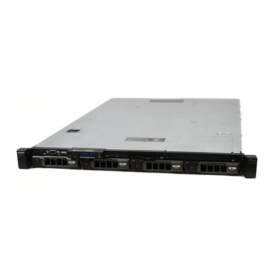
- Page 1 PowerEdge R415 Technical Guide The PowerEdge R415 offers enterprise-class features with a balance of processing power and value.
- Page 2 Inc. in the United States and/or other jurisdictions. Other trademarks and trade names may be used in this document to refer to either the entities claiming the marks and names or their products. Dell disclaims proprietary interest in the marks and names of others.
-
Page 3: Table Of Contents
Power, Thermal, Acoustic ................... 23 Power Supplies ..................23 Power Supply Specifications ................23 Heat Dissipation ..................24 Environmental Specifications ................. 24 ® ENERGY STAR Compliance ................25 Thermal ....................25 Acoustics ....................25 Processors ..................... 27 Overview ....................27 PowerEdge R415 Technical Guide... - Page 4 BIOS ......................33 Overview ....................33 Supported ACPI States ................. 34 Power Management Modes ................34 8.3.1 Dell Active Power Controller ..............34 8.3.2 Power Saving BIOS Setting (OS Control) ............34 8.3.3 Maximum Performance ................34 Embedded NICs/LAN on Motherboard (LOM) ............. 37 I/O Slots .......................
- Page 5 Figure 2. Front View (Cabled HDD with LED)..............15 Figure 3. Front View (Hot-Plug HDD with LCD) ............. 15 Figure 4. Front View (With Optional Bezel) ..............15 Figure 5. Back View (Non-Redundant Power Supply) ............15 PowerEdge R415 Technical Guide...
- Page 6 Back View of R415 Mounted in A3 Sliding Rails with CMA ........18 Figure 12. R415 Mounted in A4 Static Rails (2-Post Center Mount Configuration) ...... 19 Figure 13. PowerEdge R415 Fans ................19 Figure 14. LED panel Configuration ................20 Figure 15.
-
Page 7: Product Comparison
You’ve told us you need a server manufacturer that inspires confidence through its reliability, availability, and quality of products. That is why we have designed the PowerEdge R415 for optimal reliability and ease of use, incorporating customer-inspired features that range from robust metal hard-drive carriers and industrial-quality materials to embedded diagnostics and an optional interactive LCD screen. -
Page 8: Comparison
Plain-language diagnosis and a programmable messaging system can help you address issues quickly to simplify day-to-day monitoring. The Dell Management Console, which is included with every Dell server, provides you with a consolidated console view of your IT infrastructure. - Page 9 NICs available NICs available NICs available Optional: various NICs available 2 front, 2 rear 2 front, 2 rear, 2 2 front, 2 rear, 2 2 front, 2 rear, 1 internal internal internal Hypervisor (with internal SD card) PowerEdge R415 Technical Guide...
- Page 10 (in) 24.69 (in) 1.68 x 18.99 x 30.39 (in) Weight Max: 14.1Kg Max: 15.9Kg Max: 15.9Kg Max: 17.69Kg (31.0lbs) (35.02lbs) (35.02lbs) (39lbs) 128 GB maximum memory will be available using 16 GB DIMMs (available Q1 2011). PowerEdge R415 Technical Guide...
-
Page 11: System Overview
Dell 2 System Overview Table 2 provides an overview of the PowerEdge R415 server features. Product Features Summary Table 2. Feature Technical Specification Form Factor 1U rack Processors AMD Opteron™ 4100 series processors Processor Sockets Front Side Bus or HyperTransport-3 Links... - Page 12 Video Matrox G200eW with 8MB memory Remote Management Optional: iDRAC6 Express, iDRAC6 Enterprise, and vFlash Dell OpenManage™ featuring Dell Management Console BMC, IPMI 2.0 compliant Systems Management Lifecycle Controller enabled with optional iDRAC6 Express or iDRAC6 Enterprise and vFlash Unified Server Configurator ReadyRails™...
- Page 13 GB means 1 billion bytes and TB equals 1 trillion bytes; actual capacity varies with preloaded material and operating environment and will be less. 128 GB maximum memory will be available using 16 GB DIMMs (available Q1 2011). PowerEdge R415 Technical Guide...
-
Page 14: Mechanical
Dell 3 Mechanical 3.1 Chassis Description The PowerEdge R415 chassis was designed to deliver a value-based, high-performance server that also offers a level of redundancy. The PowerEdge R415 is available in two chassis configurations: Cabled hard drive chassis with LED module ... -
Page 15: Front Panel View And Features
3.3 Front Panel View and Features The PowerEdge R415 is available in two chassis configurations: cabled hard drive and hot-plug hard drive. The cabled hard drive chassis includes an LED control panel (Figure 2), and the hot-plug hard drive chassis includes an LCD control panel (Figure 3). -
Page 16: Power Supply Indicators
Dell Back View (Redundant Power Supply) Figure 6. See the Back-Panel Features and Indicators section in the About Your System chapter of the PowerEdge R415 Hardware Owner’s Manual on Support.Dell.com for more information. 3.5 Power Supply Indicators The PowerEdge R415 power supplies (redundant and non-redundant) have one status bi-color LED: green for AC power present and amber for a fault. -
Page 17: Internal Chassis View
Sliding Rails for 4-post racks include the following support: Toolless installation in 19‖ EIA-310-E compliant square or unthreaded round hole 4-post racks, including all generations of Dell racks Tooled installation in 19‖ EIA-310-E compliant threaded hole 4-post racks (requires the 1U Threaded Rack Adapter Brackets Kit) ... -
Page 18: Rack View
3.10.1 Sliding Rails See Figure 10 and Figure 11 for views of the PowerEdge R415 mounted in A3 sliding rails. Figure 10. R415 Mounted in A3 Sliding Rails Figure 11. Back View of R415 Mounted in A3 Sliding Rails with CMA 3.10.2... -
Page 19: Fans
Figure 13 shows the PowerEdge R415 fans. The four fans at right are the fans for the system, specifically for the processors and memory modules. The two fans at left are present when the system is configured with redundant power supplies, for which they provide cooling. -
Page 20: Led Panel Configuration
For a complete description of LED indicators, their causes, and possible courses of action to take to resolve an error, see the Diagnostic Lights (Optional) section in the About Your System chapter in the PowerEdge R415 Hardware Owner’s Manual on Support.Dell.com. 3.12.2 LCD Panel Configuration Figure 16 and Figure 17 show the LCD panel. -
Page 21: Security
3.13.2 Bezel A metal bezel is an available option and is mounted to the chassis front to provide the Dell ID. A lock on the bezel prevents unauthorized access to system peripherals and the control panel. System status remains viewable when the bezel is installed. -
Page 22: Secure Mode
NMI switches on the control panel or to set up a system password. 3.14 USB Key Dell does not offer USB keys for factory installation. The PowerEdge R415 supports two internal USB connectors which can be used for USB keys. -
Page 23: Power, Thermal, Acoustic
4 Power, Thermal, Acoustic 4.1 Power Supplies The PowerEdge R415 is powered by either a non-redundant 480W power supply or an optional redundant 500W power supply. The power supply subsystem provides power to the planar, the four internal hard drive bays, and one slim optical disk drive bay. -
Page 24: Heat Dissipation
100–240VAC, 50–60Hz, 7.5–3.8 Heat Dissipation 1637 BTU/hr maximum 1706 BTU/hr maximum 4.4 Environmental Specifications Table 6 summarizes the environmental specifications for the PowerEdge R415. Environmental Specifications Table 6. Temperature Operating 10° to 35°C (50° to 95°F) with a maximum temperature gradation of 10°C per hour... -
Page 25: Energy Star ® Compliance
Sound quality is different from sound power level and sound pressure level in that it describes how humans respond to annoyances in sound, like whistles, hums, etc. One of the sound quality metrics in the Dell specification is prominence ratio of a tone as shown in Table 7. -
Page 26: Acoustical Performance
Prominent tone: Criteria of D.5 and D.8 of ECMA-74 9th ed. (2005) are followed to determine if discrete tones are prominent. The system is placed in a rack with its bottom at 75 cm from the floor. The acoustic transducer is at front bystander position, ref ISO7779 (1999) Section 8.6.2. PowerEdge R415 Technical Guide... -
Page 27: Processors
Dell 5 Processors 5.1 Overview The PowerEdge R415 utilizes the latest four- and six-core offerings from the AMD Opteron™ 4000 series (C32). 5.2 Features Key features of the C32 processor include the following: Performance for blades and cost-effective DP servers... -
Page 28: Processor Configurations
45nm 5.4 Processor Configurations The PowerEdge R415 is a two-socket server that will operate with either a single processor or dual processors. When the R415 is configured with a single processor, the memory controller is embedded in the processor and supports 4 DIMMs (1 GB minimum and a 32 GB maximum). When two processors are installed in the system, it supports a total of 8 DIMMs (2 GB minimum and a 64 GB maximum). -
Page 29: Memory
6.2 DIMMs Supported The PowerEdge R415 supports DDR3 RDIMMs and UDIMMs. The memory interface uses 1 GB, 2 GB, 4 GB, 8 GB, and 16 GB (available Q1 2011) RDIMMs and 1 GB, 2 GB, and 4 GB UDIMMs. See Table 9. -
Page 30: Speed
Use of non-ECC UDIMMs For more information on R415 memory configurations, see the System Memory section in the Installing System Components chapter in the PowerEdge R415 Hardware Owner’s Manual on Support.Dell.com. 6.4 Speed Each processor has two DDR3 channels capable of supporting speeds up to 1333 MHz. Single- and dual-rank DIMM types can support speeds up to 1333 MHz. -
Page 31: Supported Configurations (2 Processors)
— — — 1333 1333 64GB 1333 1066 64GB 16GB — 16GB — 16GB — 16GB — 1066 1066 128GB 16GB 16GB 16GB 16GB 16GB 16GB 16GB 16GB 1066 1066 16 GB DIMMS available Q1 2011 PowerEdge R415 Technical Guide... -
Page 32: Chipset
SR5670 and the SP5100. 7.2 AMD I/O Bridges The PowerEdge R415 I/O board uses the AMD SR5670 I/O Bridges (IOB) to provide links between the C32 processor(s) and I/O components. The main components of the I/O controllers are configured to use two x16 HyperTransport-3 links (to both processors), up to 42 lanes of PCI Express Gen 2, an x4 PCIe Gen 1 Southbridge Interface (SB Link), and an integrated IOAPIC. -
Page 33: Bios
Dell 8 BIOS 8.1 Overview The PowerEdge R415 BIOS is based on the Dell BIOS core and supports the following features: AMD C32 processor support Simultaneous Multi-Threading (SMT) support PCI 2.3 compliant Plug and Play 1.0a compliant ... -
Page 34: Supported Acpi States
OS in the FACP table. Thus, a driver can directly access bits to control a device’s power management. Generic features have defined enable and status bits, but the functionality is not fully visible to the OS. Dell provides ASL code to handle the details of generic features, allowing the OS to intelligently communicate with system-specific hardware. -
Page 35: Bios Power Management Profiles
Event (PME) purpose event pin in the chipset. When a device signals PME#, the system wakes (if necessary), the OS detects the event, and a Dell-defined ASL routine handles the event. Wake-on- LAN is one example of a PME. USB Wake... - Page 36 Fan algorithm: Maximum Performance Custom CPU Power and Performance Management: Maximum Performance, Minimum Power, OS DBPM, System DBPM Memory Power and Performance Management: Maximum Performance, 1333MHz, 1067MHz, 800MHz, Minimum Power Fan Algorithm: Maximum Performance, Minimum Power PowerEdge R415 Technical Guide...
-
Page 37: Embedded Nics/Lan On Motherboard (Lom)
® The Broadcom 5716 LOM chip is located on the PowerEdge R415 motherboard. The 5716 chip is connected to the IOH via a PCI Express x4 gen2 link. The chip provides two 1xGB Ethernet ports with two RJ-45 connectors on the back of the system. The firmware for the LOM chip resides in a flash part. The PowerEdge R415 supports Wake-On-LAN (WOL) from either port. -
Page 38: O Slots
Dell 10 I/O Slots 10.1 Overview The PowerEdge R415 includes a total of two PCI Express expansion slots as follows: One x16 PCIe Gen2 slot for a full-height, full-length card (25W max) One x4 PCIe Gen1 slot for embedded SAS card only The following requirements apply for the PCIe slots: ... - Page 39 5709 Quad Port, LP & FH X4 Gen2 bracket, ToE, iSoE For more information on PCIe cards, see Expansion Cards and Expansion-Card Risers in the Installing System Components chapter in the PowerEdge R415 Hardware Owner’s Manual on Support.Dell.com. PowerEdge R415 Technical Guide...
-
Page 40: Boot Order
10.5 PCI Card Dimensions For information about PCI slots and card dimensions, see the Back-Panel Features and Indicators section in the About Your System chapter in the PowerEdge R415 Hardware Owner’s Manual on Support.Dell.com. PowerEdge R415 Technical Guide... -
Page 41: Storage
Dell 11 Storage 11.1 Overview The PowerEdge R415 supports up to four hard drives in one of the following configurations: 4 x 3.5‖ cabled SATA from motherboard SATA connector 4 x 3.5‖ cabled SAS or SATA with add-on storage controller ... - Page 42 2.5” or 3.5” Mix SAS and ASS-X Add-in SAS/SATA RAID card, no RAID (SAS 2 x SAS + 2 x SAS + Hot Plug SATA 6/iR or PERC H200) 1 x SATA 1 x SATA No RAID PowerEdge R415 Technical Guide...
-
Page 43: Persistent Storage
PERC S300 does not support Linux operating systems or VMware virtualization software. 11.3 Persistent Storage The PowerEdge R415 offers two types of persistent storage: unmanaged and managed. The following options are available for persistent storage: Unmanaged internal SD module ... -
Page 44: Led Indicators
11.7 Tape Drives External tape drives and tape libraries are supported. No internal tape drive support is available. For more information on supported tape drives and tape libraries, see http://www.dell.com/storage. 11.8 External Storage External storage devices are supported. For more information, see http://www.dell.com/storage. -
Page 45: Video
Dell 12 Video ® ® The PowerEdge R415 is equipped with a Matrox G200eW with 8 MB memory integrated in the Nuvoton WPCM450 (BMC controller). Supported resolutions are listed in Table 17. Graphics Video Modes Table 17. Resolution Refresh Rate (Hz) -
Page 46: Rack Information
Note: The PowerEdge R415 is not compatible with any other Dell rails including previous generation rails, but it does use the same sliding rails as the R310 and R410 and uses the same static rails as the R210, R310, and R410. -
Page 47: Static Rails
Figure 19. 1U Threaded Rack Adapter Brackets Kit 13.2.2 Static Rails Static rails support a wider variety of racks than the sliding rails, but do not support serviceability in the rack and are thus not compatible with the CMA. See Figure 20. PowerEdge R415 Technical Guide... -
Page 48: Supported Racks
ReadyRails/Generic Static *Requires the 1U Threaded Rack Adapter Brackets Kit (Dell PN 8Y19G) Screws are not included in the static rail kit since the threaded racks are offered with a variety of thread designations. Users must provide their own screws when mounting the static rails in threaded or 2-post racks. -
Page 49: Cable Management Arm (Cma)
A low-profile fixed tray is included to support and retain the CMA in its fully-closed position. The CMA and the tray can be mounted without the use of tools using simple and intuitive snap-in designs. PowerEdge R415 Technical Guide... -
Page 50: Operating Systems And Virtualization
Dell 14 Operating Systems and Virtualization For detailed information, see the following: • Operating System Support Matrix for Dell PowerEdge Systems on www.Dell.com • Dell PowerEdge R415 Systems Getting Started With Your System guide on Support.Dell.com PowerEdge R415 Technical Guide... -
Page 51: Systems Management
A Dell Systems Management and Documentation DVD and a Dell Management Console DVD are included with the product. ISO images are also available. A brief description of available content: • Dell Systems Build and Update Utility: Dell Systems Build and Update Utility assists in OS install and pre-OS hardware configuration and updates. •... -
Page 52: Lifecycle Controller And Unified Server Configurator
For servers without iDRAC Express, this utility has limited functionality and offers OS install and diagnostics capabilities only. To access the Unified Server Configurator, press the <F10> key within 10 seconds of the Dell logo’s appearance during the system boot process. Current functionality enabled by the Unified Server... -
Page 53: Idrac6 Enterprise
Dedicated network interface Additionally, the iDRAC6 Enterprise can be upgraded by adding the vFlash Media card. This is a 1 GB Dell branded SD card that enables a persistent 256 MB virtual flash partition. In the future, vFlash will be expanded to include additional features. - Page 54 Monitoring* Real-time Power Graphing* Historical Power Counters* Logging Features System Event Log RAC Log Trace Log PowerEdge R415 Technical Guide...
-
Page 55: Usb Peripherals
Dell 16 USB Peripherals The PowerEdge R415 supports the following USB devices: USB key (bootable) Keyboard (only one USB keyboard is supported) Mouse (only one USB mouse is supported) Optional USB DVD-ROM PowerEdge R415 Technical Guide... -
Page 56: Appendix A. Statement Of Volatility
Appendix A. Statement of Volatility The Dell PowerEdge R415 contains both volatile and non-volatile (NV) components. Volatile components lose their data immediately upon removal of power from the component. Non-volatile components continue to retain their data even after the power has been removed from the component. Components chosen as user- definable configuration options (those not soldered to the motherboard) are not included in the Statement of Volatility. - Page 57 Purpose? [e.g., boot code] Store power supply information How is data input to this memory? Programmed by the power supply manufacturer. How is this memory write protected? Not write protected PowerEdge R415 Technical Guide...
- Page 58 Purpose? [e.g., boot code] Optional embedded boot device How is data input to this memory? Factory installed or via USB bus How is this memory write protected? Not write protected PowerEdge R415 Technical Guide...
- Page 59 How is this memory write protected? Software write protected To obtain optional component information, please refer to the Dell Statement of Volatility for the individual components. Please direct any questions to your Dell Marketing contact. PowerEdge R415 Technical Guide...
-
Page 60: Appendix B. Certifications
Regulatory compliance information can be located at the following sites: Product Safety, EMC and Environmental Datasheets Dell Regulatory Compliance Home Page B.2 Product Safety Certifications The product has been certified and bears the Mark, as applicable, of the Product Safety authorities as indicated in Table 23. -
Page 61: Electromagnetic Compatibility
The product has been certified and bears the Mark, as applicable, of the Ergonomics, Acoustics, and Hygienics authorities as indicated in Table 25. Ergonomics, Acoustics and Hygienics Table 25. Country/Region Authority or Mark Belarus BELLIS Germany Russia GOST PowerEdge R415 Technical Guide... -
Page 62: Appendix C. Additional Information And Options
Dell Appendix C. Additional Information and Options The PowerEdge R415 system conforms to the industry standards detailed in Table 26. Industry Standards Table 26. Standard URL for information and specifications ACPI http://www.acpi.info/ Advance Configuration and Power Interface Specification, v2.0c Energy Star http://www.energystar.gov/index.cfm?c=archives.enterprise... - Page 63 Dell Standard URL for information and specifications Unified Extensible Firmware Interface Specification, v2.1 http://www.usb.org/developers/docs/ Universal Serial Bus Specification, Rev. 2.0 Windows Logo http://www.microsoft.com/whdc/winlogo/hwrequirements. Windows Logo Program mspx System and Device Requirements, v3.10 PowerEdge R415 Technical Guide...
Need help?
Do you have a question about the PowerEdge R415 and is the answer not in the manual?
Questions and answers