Table of Contents
Advertisement
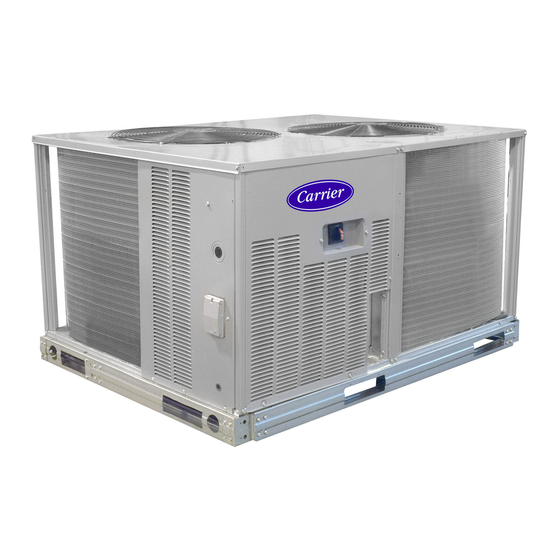
38AU
Air-Cooled Condensing Units
50 Hz
®
with Puron
(R-410A) Refrigerant
Sizes 07 - 14
CONTENTS
SAFETY CONSIDERATIONS . . . . . . . . . . . . . . . . . . . . . . . 1
INSTALLATION GUIDELINES. . . . . . . . . . . . . . . . . . . . . . . 2
INSTALLATION . . . . . . . . . . . . . . . . . . . . . . . . . . . . . . . . 9-19
Step 1 – Plan for Unit Location . . . . . . . . . . . . . . . . . . . 9
Step 2 – Complete Pre-Installation Checks. . . . . . . . . . 9
Step 3 – Prepare Unit Mounting Support . . . . . . . . . . 9
Step 4 – Rig and Mount the Unit . . . . . . . . . . . . . . . . . . 9
Step 5 – Complete Refrigerant Piping Connections . . 10
Step 6 – Install Accessories. . . . . . . . . . . . . . . . . . . . . . 14
Step 7 – Complete Electrical Connections . . . . . . . . . 14
PRE-START-UP . . . . . . . . . . . . . . . . . . . . . . . . . . . . . . . . 19
System Check . . . . . . . . . . . . . . . . . . . . . . . . . . . . . . . . . 19
Turn On Crankcase Heater . . . . . . . . . . . . . . . . . . . . . . 19
Preliminary Charge. . . . . . . . . . . . . . . . . . . . . . . . . . . . . 19
START-UP. . . . . . . . . . . . . . . . . . . . . . . . . . . . . . . . . . . . . 19 -25
38AU Units . . . . . . . . . . . . . . . . . . . . . . . . . . . . . . . . . . . 19
OPERATING SEQUENCE. . . . . . . . . . . . . . . . . . . . . . . . . . 26
Indoor (Supply) Fan . . . . . . . . . . . . . . . . . . . . . . . . . . . . 26
Cooling, Unit Without Economizer . . . . . . . . . . . . . . . . 26
Cooling, Unit With Economizer . . . . . . . . . . . . . . . . . . . 26
Heating. . . . . . . . . . . . . . . . . . . . . . . . . . . . . . . . . . . . . . . 26
ROUTINE SYSTEM MAINTENANCE. . . . . . . . . . . . . . . 26
Quarterly Inspection (and 30 days after initial start) . . 26
Seasonal Maintenance . . . . . . . . . . . . . . . . . . . . . . . . 26
SERVICE. . . . . . . . . . . . . . . . . . . . . . . . . . . . . . . . . . . . . .27 - 33
Refrigeration System . . . . . . . . . . . . . . . . . . . . . . . . . 27
Compressor Oil. . . . . . . . . . . . . . . . . . . . . . . . . . . . . . . . 27
Servicing Systems on Roofs with
Synthetic Materials. . . . . . . . . . . . . . . . . . . . . . . . . . . . . 27
Liquid Line Filter Drier . . . . . . . . . . . . . . . . . . . . . . . . . 27
Filed Refrigerant Access Ports . . . . . . . . . . . . . . . . . 27
Factory High-flow Access Ports . . . . . . . . . . . . . . . . 27
Comfort Alert Diagnostic Module. . . . . . . . . . . . . . . 28
Crankcase Heater . . . . . . . . . . . . . . . . . . . . . . . . . . . . . . 30
Compressor Protection. . . . . . . . . . . . . . . . . . . . . . . . . . 30
Low-Pressure Switches . . . . . . . . . . . . . . . . . . . . . . . . . 30
High-Pressure Switches. . . . . . . . . . . . . . . . . . . . . . . . . 30
Outdoor Fans. . . . . . . . . . . . . . . . . . . . . . . . . . . . . . . . . . 30
Lubrication . . . . . . . . . . . . . . . . . . . . . . . . . . . . . . . . . . . 30
NOVATION™ Coil Cleaning and Maintenance . . . . 33
Installation, Start-Up and
Service Instructions
Repairing NOVATION Condenser Tube Leaks . . . . 33
Replacing NOVATION Condenser Coil . . . . . . . . . . 33
Service Parts . . . . . . . . . . . . . . . . . . . . . . . . . . . . . . . 33 3
Fastener Torque Values . . . . . . . . . . . . . . . . . . . . . . . 33 3
TROUBLESHOOTING . . . . . . . . . . . . . . . . . . . . . . . . . 34 -35
APPENDIX A
Air Conditioner and Heat Pump with Puron
Quick Reference Guide . . . . . . . . . . . . . . . . . . . . . . . 36
APPENDIX B
Wiring Diagram List. . . . . . . . . . . . . . . . . . . . . . . . . 36
APPENDIX C
Motormaster Sensor Locations. . . . . . . . . . . . . . . . . 37
START-UP CHECKLIST . . . . . . . . . . . . . . . . . . . .CL-1, CL-2
SAFETY CONSIDERATIONS
Improper
installation,
adjustment,
maintenance, or use can cause explosion, fire, electrical shock
or other conditions which may cause personal injury or
property damage. Consult a qualified installer, service agency,
or your distributor or branch for information or assistance. The
qualified installer or agency must use factory-authorized kits or
accessories when modifying this product. Refer to the
individual instructions package
Follow all safety codes. Wear safety glasses and work gloves.
Use quenching cloths for brazing operations and have a fire
extinguisher available. Read these instructions thoroughly and
follow all warnings or cautions attached to the unit. Consult
local building codes for special requirements. In absence of
local codes, it is recommended that the (USA standard ANSI/
NFPA70, National Electrical Code (NEC), be followed.
It is important to recognize safety information. This is the
safety-alert symbol
. When you see this symbol on the unit
and in instructions or manuals, be alert to the potential for
personal injury.
Understand the signal words DANGER, WARNING,
CAUTION, and NOTE. These words are used with the safety-
alert symbol. DANGER identifies the most serious hazards
which will result in severe personal injury or death.
WARNING signifies hazards which could result in personal
injury or death. CAUTION is used to identify unsafe practices,
which may result in minor personal injury or product and
property damage. NOTE is used to highlight suggestions
which will result in enhanced installation, reliability, or
operation.
®
–
alteration,
service,
Advertisement
Table of Contents


Need help?
Do you have a question about the 38AUZ*07 Series and is the answer not in the manual?
Questions and answers