Table of Contents
Advertisement
Quick Links
Advertisement
Table of Contents

Related Manuals for AVer AVerVision VP-1HD


Summary of Contents for AVer AVerVision VP-1HD
- Page 1 AVerVision VP-1HD User Manual...
- Page 3 F C C N O T I C E ( C l a s s A) This device complies with Part 15 of the FCC Rules. Operation is subject to the following two conditions: (1) this device may not cause harmful interference, and (2) this device must accept any interference received, including interference that may cause undesired operation.
- Page 4 The information contained in this documentation is subject to change without notice. In no event will AVer be liable for direct, indirect, special, incidental, or consequential damages arising out of the use or inability to use this product or documentation, even if advised of the possibility of such damages.
-
Page 5: Table Of Contents
Connecting a PC or Macintosh Computer ........................... 6 Connect to a Computer via USB ..............................7 Connecting to a Microscope ................................ 8 Setting Up AVerVision VP-1HD ............................... 10 Unfolding the Unit ..................................10 Operating Height & Angle ................................11 Paper Guide ....................................11 ... - Page 6 OSD Menu ......................................15 Navigate the Menu and Submenu ............................. 16 Image ......................................17 Presentation ....................................19 Setting ....................................... 22 System ...................................... 26 Transfer Captured Images/Videos to a computer.......................... 29 Troubleshooting ....................................30 Limited Warranty ....................................31 ...
-
Page 7: Introduction
3D objects onto a TV, LCD or DLP projector making presentations a snap. RGB Cable (VGA Cable) AVerVision VP-1HD is an Power Adapter ideal presentation tool for * The power adapter will vary business, academic, depending on the country where it is... -
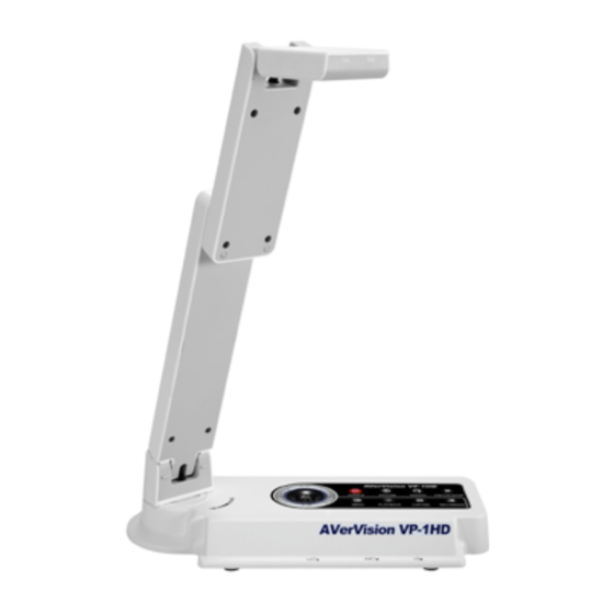
Page 8: Avervision Vp-1Hd Parts
The illustrations below identify the parts of AVerVision VP-1HD Camera head Camera lens Rear panel Control panel Right panel Paper guide Bulit-in MIC HDMI port (10) DC 12V port (11) RGB output port (12) RGB input port (13) USB OTG port... -
Page 9: Technical Specifications
Image Dimension Sensor 1/4" CMOS color image sensor Operating 275mm(L) x 114mm(W) x 335mm(H) Total Pixels 5 Mega Pixels Folded 275mm(L) x 114mm(W) x 70mm(H) 30 fps (max.) Weight 1.2 kg (about 2.64 lb) Frame Rate 15fps (1080p) Power 30fps (720p) Power Source 100-240V, 50-60Hz 1920x1080,... -
Page 10: Making The Connections
Switch function from OTG port to mini USB port. (7) Mini USB Port Connect to a mini USB port of a computer with a USB cable and use AVerVision VP-1HD as a USB Camera or transfer the captured images/videos either from the memory source to computer. -
Page 11: Connecting The Power Adapter
Connect the power adapter to a standard 100V~240V AC power source. Wall outlet Power adapter Locate the HDMI input port of the display device and connect it to HDMI port of AVerVision VP-1HD. HDMI cable HDMI monitor... -
Page 12: Connecting A Rgb, Mac Display Monitor Or Lcd/Dlp Projector
Locate the RGB input port of the display device and connect it to RGB OUT port of VP-1HD. If you are not sure, please refer to the user manual of the device. Make sure the TV/RGB switch is set to RGB. RGB cable LCD/DLP projector LCD / MAC monitor... -
Page 13: Connect To A Computer Via Usb
Locate the USB port of the computer or laptop and connect it to USB port of AVerVision VP-1HD. This enables you to use AVerVision VP-1HD as a USB Camera or to transfer the captured pictures/videos from the memory and to computer. Also see “Transfer Capture Images/Videos to a... -
Page 14: Connecting To A Microscope
Connecting the VP-1HD to a microscope enables you to examine microscopic objects on a big screen without straining your eyes. Adjust the focus of the microscope. Change the image display mode to Microscope. Press MENU > select IMAGE tab > select MODE > select (microscope) and press Select the appropriate rubber coupler size for the microscope... - Page 15 Attach the microscope adapter to the AVerVision camera head. Then connect it to the AVerVision and microscope. 5. Microscope Adapter 4. Microscope eyepiece Microscope...
-
Page 16: Setting Up Avervision Vp-1Hd
This section provides useful tips on how to setup the VP-1HD to meet your needs. Follow the step by step procedure below to setup the unit. (1) Unfold the arm. (2) Turn 90° to the left. (3) Swivel up to the left. (4) Fold the camera down. -
Page 17: Operating Height & Angle
& & The approximate height of the arm should be 335mm and angled at 53° to display an A4 size landscape document. The A4 paper marks serve as a guide for placing the A4 document under the camera. The approximate shooting area of VP-1HD is 340mm x 255mm. 340 mm 340 mm 255 mm... -
Page 18: External Memory Storage
If no external storage is connected, all captured still images will be saved in the built-in memory. Make sure to set the USB Flash Drive switch o the right before inserting a USB flash drive. AVerVision VP-1HD can support USB flash drive from 2GB to 32GB (FAT). -
Page 19: Touch Button Control Panel
The touch button control panel located on the top side of the VP-1HD provides quick access to commonly used functions. (10) AUTO (11) Function Description (1) POWER Turn the unit on/standby. To turn off, press hold POWER button for 5 sec. (2) PC/CAM Switch between Camera and PC mode. -
Page 20: Control Panel Light Color
Function Description View & playback captured still images and audio video files. Press PLAYBACK button, the screen will switch to (7) PLAYBACK playback mode. Press ►, ◄, ▼, and▲ to choose a selection in the playback list. To Exit playback mode, press PC/CAM button. -
Page 21: Osd Menu
There are 4 tabs on the OSD menu: IMAGE, PRESENTATION, SETTING and SYSTEM. PRESENTATION IMAGE SYSTEM SETTING... -
Page 22: Navigate The Menu And Submenu
1. Press MENU button on the remote or control panel. 2. Press ► and ◄ to toggle between tabs 3. Press ▼ and ▲ to choose a selection in the menu list. 4. Press to make a selection. 5. Use ► and ◄ to adjust the setting or make a selection. 6. -
Page 23: Image
Menu Screen Function Brightness Adjust brightness level manually between 0 and 63. Contrast Adjust the contrast level manually between 0 and 255 under bright and dark environments. - Page 24 Menu Screen Function Mode Select from the various image display settings. Sharp - adjust the contrast along the edges making text appear more visible. Graphics - adjust the gradient of image. Motion - increase frame rate. Sufficient lighting is required when using this mode. Microscope - automatically adjust optical zoom for microscopic viewing.
-
Page 25: Presentation
Menu Screen Function Spotlight Spotlight overlays a frame on the presentation screen. You can move the Spotlight around the presentation screen using the ▲, ▼, ◄, & ► buttons. Select Execute to call the Spotlight submenu. In the Spotlight submenu, the following options are available. ON/OFF –... - Page 26 Menu Screen Function Visor Visor covers the presentation screen. The upper part of the presentation screen is slightly exposed. Use the ▲, ▼, ◄, & ► buttons to reveal more of the covered area. Select Execute to call the Visor submenu.
- Page 27 Menu Screen Function Select the thumbnail playback screen location and show the thumbnail playback screen at the corner of the screen to recall the captured image from the memory in Camera mode. Select OFF to cancel PIP. Lower Left Upper Left Upper Right Lower Right Split Screen...
- Page 28 Menu Screen Function Capture Select to set the capture resolution, quality, type and interval settings. Resolution Select the capture size. In 5M setting, the capture resolution size is 2560 X 1920.
-
Page 29: Setting
Menu Screen Function Quality Select the capture compression setting. Type Select the capture type. Single - capture one picture only. Continuous - capture successive pictures. Interval The interval function is not available for VP-1HD model. - Page 30 Menu Screen Function Recording Select the video recording compression setting. Storage The VP-1HD only support save the audio & video recording in USB flash drive. Format Format to delete all the data in the selected memory.
- Page 31 Function USB to PC Select the status of the AVerVision VP-1HD when it is connected to the computer via USB. Make sure the USB switch on the left panel is set to Camera - can be used as a computer webcam or with our bundled software to record video and capture still image.
-
Page 32: System
Menu Screen Function Language Change and select different language. Output Display Set the resolution to display the image on screen. This selection will be disabled in TV output mode. - Page 33 Menu Screen Function Backup The backup function is not available for VP-1HD model. Save Setting Save current setting in the selected profile number. Only effect, mode, brightness and contrast settings can be saved. Recall Setting Restore the setting back to the selected profile number.
- Page 34 Menu Screen Function Information Display the product information. Default Restore all the settings into original factory default setting.
-
Page 35: Transfer Captured Images/Videos To A Computer
The instruction below MUST be read and followed BEFORE connecting the USB cable. 1. Make sure to set the USB switch to for the computer to detect AVerVision VP-1HD. 2. MUST set the USB to PC as STORAGE before connecting the USB cable. -
Page 36: Troubleshooting
This section provides many useful tips on how to solve common problems while using the VP-1HD. There is no picture on the presentation screen. 1. Check all the connectors again as shown in this manual. 2. Check the on/off switch of the display output device. 3. -
Page 37: Limited Warranty
This limited warranty extends only to You as the original purchaser. Except for the foregoing, the Product is provided “AS IS.” In no event does AVer warrant that You will be able to operate the Product without problems or interruptions, or that the Product is suitable for your purposes. - Page 38 THEORY, EVEN IF AVER HAS ADVISED OF THE POSSIBILITY OF SUCH DAMAGES. AVER’S TOTAL, AGGREGATE LIABILITY FOR DAMAGES OF ANY NATURE, REGARDLESS OF FORM OF ACTION, SHALL IN NO EVENT EXCEED THE AMOUNT PAID BY YOU TO AVER FOR THE SPECIFIC PRODUCT UPON WHICH LIABILITY IS BASED.
- Page 40 P/N: 300AP0G1BDWM...
Need help?
Do you have a question about the AVerVision VP-1HD and is the answer not in the manual?
Questions and answers