Table of Contents
Advertisement
Quick Links
Download this manual
See also:
Quick Manual
Advertisement
Table of Contents

Related Manuals for AVer AVerVision W30


Summary of Contents for AVer AVerVision W30
- Page 1 ENGLISH AVerVision W30 User Manual...
- Page 2 The information contained in this documentation is subject to change without notice. In no event will AVer be liable for direct, indirect, special, incidental, or consequential damages arising out of the use or inability to use this product or documentation, even if advised of the possibility of such damages.
- Page 3 ENGLISH Remote Control B a t t e r y S a f e t y I n f o r m a t i o n Store batteries in any cool & dry place. Do not dispose used batteries in domestic waste. Dispose batteries at special collection points or return to stores if applies.
-
Page 4: Table Of Contents
ENGLISH 0 B P ackage Contents ................1 1 B O ptional Accessories ..............1 Get Familiar with the AVerVision W30 ........... 2 Camera ....................2 Right Panel ..................2 Control Panel ..................3 LED Light ..................3 Base ....................... 4 Rear Panel .................. - Page 5 ENGLISH 4 0 B P resentation ..................23 6 3 B C C AM / RGB IN ................23 6 3 B S plit Screen..................23 6 2 B P IP ....................23 6 4 B T imer ....................24 Setting ....................
-
Page 6: P Ackage Contents
ENGLISH Make sure the following items are included in the package. USB Cable W30 (base) RCA Cable RGB Cable W30 (camera) RS-232/CVBS Cable x2 Power Adapter (12V, 3A) * The power adapter will vary depending on the standard Software & Manual CD power outlet of the country Remote Control where it is sold. -
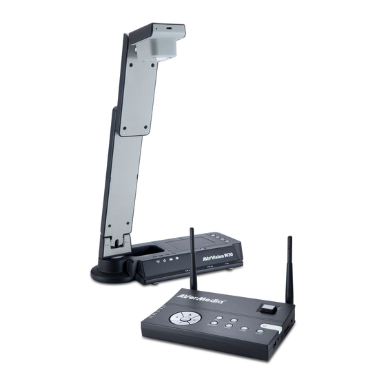
Page 7: Get Familiar With The Avervision W30
ENGLISH Ca me r a (fig. 1.1) Name Function Camera Head Contain the camera sensor. Camera Lens Focus the image in the camera. Control Panel Easy access to various functions. Connection for the power adapter to charge the battery and binding Right Panel button to tie up with the W30 base. -
Page 8: Control Panel
ENGLISH Control Panel (fig. 1.3) Name Function Power Turn the W30 camera on/off. Zoom + Increase the magnification of the W30 camera image. Zoom - Decrease the magnification of the W30 camera image. Auto Focus Adjust the focus automatically. LED Light (fig. -
Page 9: Base
ENGLISH Ba s e (fig. 1.5) Name Function Antenna Send and receive data signal to and from W30 camera and base. Connections for computer, RGB/DVI-I/RCA external display device, and Rear Panel RS-232 communication port. Control Panel Easy access to various functions. IR Sensor Receive remote control commands. -
Page 10: Right Panel
ENGLISH Name Function Connect the supplied RS-232/CVBS cable into this port. The RCA jack outputs the video signal from the camera to a TV or RS-232/CVBS port video equipment. The RS-232 jack is used to connect to computer serial port or to any control panel or for centralized control if desire. -
Page 11: Control Panel
ENGLISH Control Panel (12) (11) (10) (fig. 1.9) Name Function POWER Turn the unit on/standby mode. AUTO FOCUS Adjust the focus automatically. RECONNECT Reconnect the W30 camera and base. SOURCE Select from 6 types of display options. CAM – display the video signal from the W30 camera. ... -
Page 12: Remote Control
- Move the selection in Playback mode and in OSD menu. The remote control requires two (2) “AAA” size batteries (supplied), make sure batteries are installed properly before use. You can access all the features of AVerVision W30 with the remote. - Page 13 ENGLISH Name Function Display a thumbnail size picture from the memory at the corner of the screen and on top of the W30 camera live image. (22 ) (21 ) Press to only display the (20 ) selected image in full screen and (10 ) again to revert back to thumbnail size (19 )
- Page 14 ENGLISH Name Function (14) BRIGHTNESS Adjust the brightness. (15) ZOOM +/- - Increase/decrease the image magnification in camera and picture (22 ) playback mode. (21 ) - Use to easily page up and page down (20 ) 16-thumbnail picture preview. (10 ) (19 ) - Make a selection in Playback mode...
-
Page 15: M Aking The Connection
ENGLISH Before making the connection, make sure the power of all devices are turned off. If you are not sure on where to connect, simply follow the illustrated connections below and also refer to the user manual of the device you are connecting the W30 base with. 2 1 B The TV-RGB switch determines the display output selection. -
Page 16: 3 B C Onnect To A Monitor Or Lcd/Dlp Projector With Dvi-I Interface
ENGLISH 2 3 B Locate the DVI-I input port of the display device and connect it to DVI-I OUT port of W30 base. Make sure the TV/RGB switch is set to RGB. LCD Monitor DVI cable with DVI interface (not supplied) DVI cable LCD/DLP projector (not supplied) -
Page 17: 5 B C Onnecting The Power
ENGLISH 2 5 B Connect the power adapter to a standard 100V~240V AC power outlet. The unit automatically in standby mode once the power is connected. Press to turn on. Wall outlet Power adapter 2 6 B Locate the RGB (VGA) output port of the computer or laptop and connect it to RGB IN port of W30 base. -
Page 18: 7 B C Onnect To A Computer Via Usb
ENGLISH 2 7 B Set the USB switch on W30 base right panel to and the LED on the control panel will light up. This enables you to use W30 as a USB Camera or to transfer the captured pictures from the memory source and to computer. -
Page 19: 0 B C Onnect To A Microscope
ENGLISH 3 0 B Connect the W30 camera to a microscope enables you to examine microscopic objects on a big screen. Change the image display mode to Microscope. Press MENU > select IMAGE tab > select MODE > select (microscope) and press Aim the camera head at the farthest point and press AUTO FOCUS. -
Page 20: S Etting Up And Operating W30
ENGLISH Be sure to match the latches to the holes and the arrow on the microscope adapter and W30 camera head are on the same side. Connect and then twist counterclockwise to lock. This section provides useful tips on how to adjust the W30 to meet your needs. Follow the step by step procedure below to setup the unit. -
Page 21: W30 Camera Operating Height & Angle
ENGLISH & & The approximate height of W30 camera should be at 336mm and angled at 55° to display a A4 size landscape document. 90° 336 mm 90° 140 mm The A4 paper marks serve as a guide for placing the A4 document under the camera. The approximate shooting area of W30 camera is 330mm x 248mm. -
Page 22: I Nfrared Sensor
ENGLISH The IR sensor is located on the W30 base only. Aim the remote control at the infrared sensor to operate the unit. 3 6 B W30 supports both SD memory card and USB flash drive for more image capture capacity. It can detect when there is an external storage media and automatically switch to the last detected storage. -
Page 23: I N S E R T A U S B F L A S H D R I V E
ENGLISH 4 5 B 1. Set the USB switch on W30 base right panel to . W30 will then detect the USB flash drive and the LED on the control panel will light up. 2. Connect the USB flash drive in the USB slot. W30 can support USB flash drive from 2GB to 64GB (FAT32). -
Page 24: O Sd Menu
ENGLISH There are 5 tabs on the OSD menu: IMAGE, PRESENTATION, SETTING and SYSTEM. In Playback mode, you can access PLAYBACK OSD menu to enable the Slide Show feature and modify Slide Show interval and transition setting if desire. For TV output, the RESOLUTION will be disabled in SETTING menu list. IMAGE PRESENTATION SETTING... -
Page 25: 7 B N Avigate The Menu And Submenu
ENGLISH 3 7 B 1. Press MENU button on the remote or control panel. 2. Press ► and ◄ to toggle between tabs 3. Press ▼ and ▲ to choose a selection in the menu list. 4. Press to make a selection. 5. -
Page 26: 9 B M Ode
ENGLISH Menu Screen Function M ode 4 9 B Select from the various image display settings. Sharp - adjust the contrast along the edges making text appear more visible. Graphics - adjust the gradient of image. Motion - increase frame rate. Sufficient lighting is required when using this mode. -
Page 27: 8 B A Uto Image
ENGLISH Menu Screen Function A uto Image 4 8 B Select ON or OFF to automatically adjust the white balance and exposure setting, and correct the color and exposure compensation. E xposure 5 3 B Select the exposure setting. AUTO - automatically adjust the camera exposure and the amount of light required. -
Page 28: 0 B P Resentation
ENGLISH 4 0 B Menu Screen Function C AM / RGB IN 6 3 B C Select to change the layout of the CAM/RGB IN. The display layout can only be changed when W30 is in CAM/ RGB IN mode. To switch to this mode, press SOURCE button and select CAM/RGB IN. -
Page 29: 4 B T Imer
ENGLISH Menu Screen Function T imer 6 4 B Start/Pause/Stop the timer and set the timer duration. The timer automatically counts up after the countdown reaches zero to show the elapsed time. Even when you switch between different video display sources, the timer will continue. -
Page 30: 8 B T Ype
ENGLISH Menu Screen Function T ype 6 8 B Select the capture type. Single - capture one picture only. Continuous - capture successive pictures. I nterval 6 9 B Set the time interval for continuous capture. The length can be set up to 600 sec (10 min). S torage 7 2 B Change the storage location. -
Page 31: 5 B F Licker
ENGLISH Menu Screen Function F licker 5 5 B Select between 50Hz or 60Hz. Some display devices cannot handle high refresh rates. The image will flicker a couple of times as the output is switched to another refresh rate. 4 2 B 4 1 B Menu Screen Function B inding... -
Page 32: 8 B S Ave Setting
ENGLISH Menu Screen Function S ave Setting 7 8 B Save current setting in the selected profile number. Only effect, mode, brightness and contrast settings can be saved. Recall Setting Restore the setting back to the selected profile number. I nformation 8 0 B Display the product information. -
Page 33: Playback
ENGLISH Menu Screen Function S lide Show 8 1 B Start/stop to display all captured images in an automated slide show. Interval Set the interval before displaying the next picture. The length can be set up to 100 sec. S lide Show Effect 8 3 B Select the slide show transition effect. -
Page 34: 5 B D Elete All
ENGLISH Menu Screen Function D elete All 8 5 B Permanently delete all the data in selected memory source. A Warning Message will appear. Select YES to continue and NO to stop deleting all the data. This enables you to transfer the captured image from the built-in memory or SD to a computer. -
Page 35: T Echnical Specifications
ENGLISH I mage 8 6 B 8 6 B Sensor 1/2” CMOS Pixel Count 3 megapixels Frame Rate 30 fps (max.) White Balance Auto / Manual Exposure Auto / Manual Image mode Sharp / Graphics / Motion / Microscope Effect Color / B/W / Negative / Mirror / Freeze 1920 x 1080, 1600x1200, 1280x1024, 1280x720, 1024x768, RGB output... -
Page 36: E Xternal Storage
ENGLISH E xternal Storage Secure Digital (SDHC) 1GB ~ 32GB (FAT32) USB Flash Drive 2GB ~ 64GB (FAT32) W30 can be controlled using a computer or any centralized control panel through RS- 232 connection. The command code for RS-232 is provided for the system integrator to be able to incorporate it with the system program. -
Page 37: Rs-232 Transmission Specifications
ENGLISH Start bit 1 bit Data bit 8 bit 1 bit Stop bit None Parity bit None X parameter 9600bps Baud rate(Communication speed) Send Device Code(1 Byte) : 0x52 Type Code(1 Byte) : 0x0B DataLength Code(1 Byte) : 0x03 Data Code(1 Byte) - Page 38 ENGLISH Function Data[0] Data[1] Data[2] CheckSum TIMER START 0x06 0x00 0x00 0x5D TIMER PAUSE 0x07 0x00 0x00 0x5C TIMER STOP 0x08 0x00 0x00 0x53 TIMER SET TIME 0x09 Value[1~120] 0x00 PREVIEW MODE: TEXT 0x0B 0x00 0x00 0x50 PREVIEW MODE: GRAPHIC 0x0B 0x01 0x00...
- Page 39 ENGLISH Function Data[0] Data[1] Data[2] CheckSum FLICKER: 60Hz 0x1C 0x01 0x00 0x46 FLICKER: AUTO 0x1C 0x02 0x00 0x45 PIP: OFF 0x23 0x00 0x00 0x78 PIP: ON 0x23 0x01 0x00 0x79 PIP POSITION: BOTTOM LEFT 0x24 0x00 0x00 0x7F PIP POSITION: TOP LEFT 0x24 0x01 0x00...
-
Page 40: 3 B R S-232 Get Command Table
ENGLISH Function Data[0] Data[1] Data[2] CheckSum BACKUP TO THUMBDRIVE 0x32 0x01 0x00 0x68 PROFILE SAVE: PROFILE 1 0x33 0x00 0x00 0x68 PROFILE SAVE: PROFILE 2 0x33 0x01 0x00 0x69 PROFILE SAVE: PROFILE 3 0x33 0x02 0x00 0x6A PROFILE RECALL: PROFILE 1 0x34 0x00 0x00... -
Page 41: Troubleshooting
ENGLISH CheckSum Function Data[0] ReData[0] Code Power Status 0x04 0x5C 0 : OFF 1: ON Lamp Status 0x05 0x5D 0 : OFF 1: ON 0: Camera Mode Display Status 0x06 0x5E 1: Playback Mode 2: PC-1 Pass Through Video Output Status 0x07 0x5F 0: VGA 1: TV... -
Page 42: 5 B L Imited Warranty
You as the original purchaser. Except for the foregoing, the Product is provided “AS IS.” In no event does AVer warrant that You will be able to operate the Product without problems or interruptions, or that the Product is suitable for your purposes. Your exclusive remedy and the entire liability of AVer under this paragraph shall be, at AVer’s option, the repair or... - Page 43 CONNECTION WITH THIS LIMITED WARRANTY, OR THE USE OR PERFORMANCE OF ANY PRODUCT, WHETHER BASED ON CONTRACT OR TORT, INCLUDING NEGLIGENCE, OR ANY OTHER LEGAL THEORY, EVEN IF AVER HAS ADVISED OF THE POSSIBILITY OF SUCH DAMAGES. AVER’S TOTAL, AGGREGATE LIABILITY FOR DAMAGES OF ANY NATURE, REGARDLESS OF FORM OF ACTION, SHALL IN NO EVENT EXCEED THE AMOUNT PAID BY YOU TO AVER FOR THE SPECIFIC PRODUCT UPON WHICH LIABILITY IS BASED.