
Subscribe to Our Youtube Channel
Related Manuals for AIREDALE LogiCool InRak


Summary of Contents for AIREDALE LogiCool InRak
- Page 1 LogiCool InRak™ • Direct Expansion • Chilled Water • Dual Circuit Chilled Water Technical Manual FM00542 EMS52086...
-
Page 2: Customer Services
Customer Services Warranty, Commissioning & Maintenance As standard, Airedale guarantees all non consumable parts only for a period of 12 months, variations tailored to suit product and application are also available; please contact Airedale for full terms and details. To further protect your investment in Airedale products, Airedale can provide full commissioning services, comprehensive maintenance packages and service cover 24 hours a day, 365 days a year (UK mainland). -
Page 3: Health And Safety
Airedale recommends that personal protective equipment is used whilst installing, maintaining and commissioning equipment. Refrigerant Warning The Airedale LogiCool InRak unit uses R410A refrigerant which requires careful attention to proper storage and handling procedures. Use only manifold gauge sets designed for use with R410A refrigerant. Use only refrigerant recovery units and cylinders designed for high pressure refrigerants. -
Page 4: Environmental Considerations
Airedale Ltd endeavours to ensure that the information in this document is correct and fairly stated, but none of the statements are to be relied upon as a statement or representation of fact. Airedale Ltd does not accept liability for any error or omission, or for any reliance placed on the information contained in this document. -
Page 5: Table Of Contents
IT Cooling LogiCool InRak™ Contents Customer Services Health and Safety Manual Handling Environmental Considerations Freeze Protection Environmental Policy Specifiers Guide Nomenclature Introduction Standard and Optional Features Unit Overview Front Door Assembly Rear Door Assembly Optional Features Packaging Cooling Mode - Chilled Water Cooling (C0) - Page 6 LogiCool InRak™ IT Cooling Contents Installation Dimensions Unpacking and Lifting Positioning Levelling Incoming Services Electrical Services Incoming Cabling Interconnecting Wiring Refrigeration Pipe work Refrigerant Pipe Sizing Guide Oil Charging Guide System Refrigerant Charging Breaking the System Vacuum Operation Checks Evaporator Superheat...
-
Page 7: Specifiers Guide
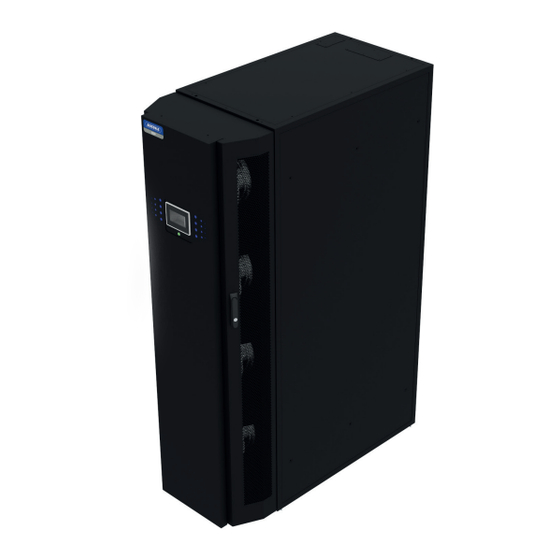
380V / 3PH /N/ 60Hz Introduction The LogiCool InRak is an efficient in-row IT cooling solution for data centre applications. The InRak delivers complete confidence, with redundancy features such as hot swappable fans and dual power supplies. It is extremely efficient, offering the latest fan technology coupled with sophisticated controls logic designed to optimise operation. -
Page 8: Standard And Optional Features
LogiCool InRak™ IT Cooling Standard and Optional Features ● ● ● ● Hot Swappable Fan Assembly ● ● ● ● Independent Fan Isolation ● ● ● ● Discharge Grille ● ● ● ● Removable Access Panel ● ● ● ●... - Page 9 IT Cooling LogiCool InRak™ Standard and Optional Features ● ● ● ● Microprocessor Control ● ● ● ● Graphical Display ● ● ● ● Unit Status LED ● ● ● ● Dew Point Control ○ ○ ○ ○ Filter Change Monitoring ○...
-
Page 10: Unit Overview
LogiCool InRak™ IT Cooling Unit Overview Standard Front Door Features • Hot Swappable Fan Assembly • Independant Fan Isolation • Discharge Grille • Removable Access Panel • Secure Door Lock Standard Construction Features • Levelling Feet • Castors • Anti-Recirculation Brush Seal •... - Page 11 IT Cooling LogiCool InRak™ Unit Overview Standard Rear Door Features • Secure Door Lock • Return Air Grille • Mains Isolator Optional Rear Door Features • G4 Return Door Air Filter Standard Electrical Components • Electrical Switch Gear • Door Electric Isolator •...
-
Page 12: Front Door Assembly
LogiCool InRak™ IT Cooling Front Door Assembly# Standard Features EC Fan motor 310mm diameter backward curved centrifugal fans with EC motors mounted with inlet ring shall be provided to ensure optimum efficiency. The fan section shall be designed as a hot swap assembly which can be changed quickly minimising downtime during replacement or maintenance. -
Page 13: Rear Door Assembly
Units shall be supplied complete with additional LAT corner protection and cross braces to afford extra transit protection. Sterling board heat treated man made material shall be used (including pallet) to comply with phytosanity import regulations (please contact Airedale for this option). InRak™ Technical Manual 7462807 V1.11.0_04_2016... -
Page 14: Cooling Mode - Chilled Water Cooling (C0)
LogiCool InRak™ IT Cooling Cooling Mode - Chilled Water Cooling (C0) Standard Features Chilled Water Coil 3/8” plain tube cooling coil with 1.8 mm fin pitch and hydrophilic fins. Dependant on model the coil shall be single (C0) or dual circuit (CC). -
Page 15: Cooling Mode - Direct Expansion Cooling (Dx)
IT Cooling LogiCool InRak™ Cooling Mode - Direct Expansion Cooling (DX) Single EC Inverter Driven Compressor Comprising of an EC inverter driven scroll compressor which provides variable control of the system performance, by adjusting its speed. This output allows external load demands to be met with greater precision, eliminating unnecessary temperature and humidity variations. - Page 16 LogiCool InRak™ IT Cooling Refrigeration Components Standard Features Oil Separator Fitted to ensure higher than usual levels of circulatory oil of the variable speed compressor stay within the unit, and are not lost to external pipe work causing damage to the compressor.
-
Page 17: Electrical
IT Cooling LogiCool InRak™ Electrical Standard Electrical features include • Mains Isolator • MCB’s • Withdrawable Main Control Panel Ultracap UPS The Ultracap module is an external backup device for the controller. The module guarantees temporary power to the controller in the event of power failures and allows for enough time to keep the controller running with time to change power supplies. -
Page 18: Controls
LogiCool InRak™ IT Cooling Controls Display/Keypad The display keypad features a simple array of keys to navigate through the in built menus. With an 8 x 22 character (132 x 64 pixel) screen size, back lit in white for improved contrast, the large screen shall provide for user friendly viewing and easy status recognition by displaying a combination of text and icons. - Page 19 IT Cooling LogiCool InRak™ Controls Standard Features Temperature/ Humidity Sensor Unit mounted temperature and humidity sensor shall be supplied as standard. This shall be mounted at the inlet side of the unit monitoring return air conditions. Water Temperature Sensor A water temperature sensor shall be fitted to the water inlet pipe work.
- Page 20 Controls Lon BMS Connection The Airedale controllers, using special serial cards, shall be integrated into LonWorks® networks. The RS485 and the FTT10 standards shall be supported by the LonWorks® serial cards. The types of LonWorks® serial cards shall be FTT-10A 78 kbs (TP/FT-10) on the LonWorks® network.
- Page 21 IT Cooling LogiCool InRak™ Controls Dynamic Pressure Control (DX units) With DX units the fans will operate with constant pressure control except the fan speed will modulate within predefined upper and lower limits, to maintain the target differential whilst maintaining the evaporating temperature.
-
Page 22: Technical Data - Direct Expansion
LogiCool InRak™ IT Cooling Technical Data - Direct Expansion Operating Limits Cooling °C Room Temperature Room RH at 24°C °C Return Air Temperature Outdoor Ambient °C Cold Aisle Hot Aisle Moisture Content Operating Band Dry Bulb temperature °C) CAUTION Low humidity in a data centre may cause static electricity build up. -
Page 23: Performance Data - Single Compressor (X1)
IT Cooling LogiCool InRak™ Technical Data - Direct Expansion Performance Data - Single Compressor (X1) Full Load (X1) Ambient (°C) Unit Air On DB / RH 18.83 18.83 21.14 20.33 20.50 Gross Total Cooling (kW) 25°C / 42% 4.43 4.43 6.19... -
Page 24: Performance Data - Tandem Compressor (X2)
LogiCool InRak™ IT Cooling Technical - Direct Expansion Performance Data - Tandem Compressor (X2) Full Load (X2) Ambient (°C) Unit Air On DB / RH 27.62 27.62 26.66 25.51 26.53 Gross Total Cooling (kW) 25°C / 42% 7.29 7.29 7.97 8.81... - Page 25 IT Cooling LogiCool InRak™ Technical - Direct Expansion Performance Data - Single Compressor (X1) Max EER (X1) Ambient (°C) Unit Air On DB / RH Gross Total Cooling (kW) 10.85 10.85 10.97 10.52 13.66 25°C / 42% 2.15 2.15 2.27 2.58...
- Page 26 LogiCool InRak™ IT Cooling Technical - Direct Expansion Performance Data - Tandem Compressor (X2) Max EER (X2) Ambient (°C) Unit Air On DB / RH Gross Total Cooling (kW) 14.94 14.94 14.82 14.24 13.80 25°C / 42% 3.22 3.22 3.30 3.70...
- Page 27 IT Cooling LogiCool InRak™ Intentionally Blank InRak™ Technical Manual 7462807 V1.11.0_04_2016...
-
Page 28: Mechanical Data - Single Compressor (X1)
LogiCool InRak™ IT Cooling Technical - Direct Expansion Mechanical Data - Single Compressor (X1) LIR6042U-X123 LIR6042U-X130 Standard Condenser Match CR50 CR50 Capacity Nom Cooling (Gross) 34.24 35.21 Nom Power Input 11.98 12.16 Nom EER 2.86 2.90 Capacity Steps 10 - 100% Modulation Dimensions –... -
Page 29: Electrical Data - Single Compressor (X1)
IT Cooling LogiCool InRak™ Technical - Direct Expansion Electrical Data - Single Compressor (X1) LIR6042U-X123 LIR6042U-X130 Standard Condenser Match - CR50 CR50 Unit Data Cooling only Nominal Run Amps 20.1 21.2 Maximum Start Amps 27.3 27.3 Recommended Mains Fuse Size Max Mains Incoming Cable Size mm²... -
Page 30: Mechanical Data - Tandem Compressor (X2)
LogiCool InRak™ IT Cooling Technical - Direct Expansion Mechanical Data - Tandem Compressor (X2) LIR6042U-X240-0 LIR6042U-X250-0 Standard Condenser Match CR65 CR80 Capacity Nom Cooling (Gross) 48.17 50.75 Nom Power Input 17.34 17.17 Nom EER 2.78 2.95 Capacity Steps 10 - 100% Modulation Dimensions –... -
Page 31: Electrical Data - Tandem Compressor (X2)
IT Cooling LogiCool InRak™ Technical - Direct Expansion Electrical Data - Tandem Compressor (X2) LIR6042U-X240-0 LIR6042U-X250-0 Standard Condenser Match - CR65 CR80 Unit Data Cooling only Nominal Run Amps 27.9 29.4 Maximum Start Amps 89.3 89.3 Recommended Mains Fuse Size Max Mains Incoming Cable Size mm²... -
Page 32: Sound Data - (X1 / X2)
LogiCool InRak™ IT Cooling Technical - Direct Expansion Sound Data - (X1 / X2) Frequency (Hz) dB Overall Fan load % Sound Measurement dB(A) 1000 2000 4000 8000 Overall Lw Sound Pressure @ 1m LIR6042U-X123 Overall Lw Sound Pressure @ 1m... -
Page 33: Technical Data - Chilled Water
IT Cooling LogiCool InRak™ Technical Data - Chilled Water Operating Limits Cooling °C Room Temperature Room RH at 24°C °C Return Air Temperature °C Entering Water Temperature °C Leaving Water Temperature Cold Aisle Hot Aisle Moisture Content Operating Band Max 2°C ∆T Minimum Water Temperature Dry Bulb temperature °C) -
Page 34: Performance Data - (C0)
LogiCool InRak™ IT Cooling Technical Data - Chilled Water Performance Data - (C0) Full Load - (C0) Water Temperatures (°C) Air On DB / RH 10/16 11/17 12/18 13/19 14/20 20.28 18.67 17.20 15.54 13.34 Gross Total Cooling (kW) 25°C / 42% Power Input (kW) 0.36... - Page 35 IT Cooling LogiCool InRak™ Technical Data - Chilled Water Performance Data - (C0) Full Load - (C0) Water Temperatures (°C) Air On DB / RH 10/16 11/17 12/18 13/19 14/20 24.53 22.28 20.11 18.02 16.00 Gross Total Cooling (kW) 25°C / 42% Power Input (kW) 0.97...
- Page 36 LogiCool InRak™ IT Cooling Technical Data - Chilled Water Performance Data - (C0) Part Load - (C0) Water Temperatures (°C) Air On DB / RH 10/16 11/17 12/18 13/19 14/20 11.39 10.60 9.95 9.22 8.17 Gross Total Cooling (kW) 25°C / 42% Power Input (kW) 0.08...
- Page 37 IT Cooling LogiCool InRak™ Technical Data - Chilled Water Performance Data - (C0) Part Load - (C0) Water Temperatures (°C) Air On DB / RH 10/16 11/17 12/18 13/19 14/20 Gross Total Cooling (kW) 14.52 13.66 12.81 11.62 9.78 25°C / 42% 0.15...
-
Page 38: Mechanical Data - (C0)
LogiCool InRak™ IT Cooling Technical Data - Chilled Water Mechanical Data - (C0) LIR6042U-C030 LIR6042U-C040 LIR6042U-C045 LIR6042U-C060 Capacity Nom Cooling (Gross) 37.04 44.87 51.47 64.02 Nom Fan Power Input 0.36 0.65 1.15 2.43 Nom EER 102.89 69.03 44.76 26.35 Dimensions – H x W x D... -
Page 39: Electrical Data - (C0)
IT Cooling LogiCool InRak™ Technical Data - Chilled Water Electrical Data - (C0) LIR6042U-C030 LIR6042U-C040 LIR6042U-C045 LIR6042U-C060 Standard Outdoor Unit Match - Chiller Chiller Chiller Chiller Unit Data Cooling only Nominal Run Amps Maximum Start Amps Recommended Mains Fuse Size Max Mains Incoming Cable Size mm²... -
Page 40: Sound Data - (C0)
LogiCool InRak™ IT Cooling Technical Data - Chilled Water Sound Data - (C0) Frequency (Hz) dB Overall Fan load % Sound Measurement dB(A) 1000 2000 4000 8000 Overall Lw Sound Pressure @ 1m LIR6042U-C030 Overall Lw Sound Pressure @ 1m... -
Page 41: Unit Pressure Drops (C0)
IT Cooling LogiCool InRak™ Technical Data - Chilled Water Unit Pressure Drops (C0) InRak C0 Unit Pressure Drop Curves Flow Rate (l/s) LIR6042U-C045-0, LIR6042U-C060-0, LIR6042U-C045-1, LIR6042U-C060-1. LIR6042U-C030-0, LIR6042U-C040-0, LIR6042U-C030-1, LIR6042U-C040-1. Unit and Solenoid Valve Pressure Drops (C0) InRak C0 Unit Pressure Drop Curves Including Inlet / Outlet Solenoid Valves Flow Rate (l/s) LIR6042U-C045-0, LIR6042U-C060-0, LIR6042U-C045-1, LIR6042U-C060-1. -
Page 42: Technical Data - Dual Circuit Chilled Water
LogiCool InRak™ IT Cooling Technical Data - Dual Circuit Chilled Water Operating Limits Cooling °C Room Temperature Room RH at 24°C °C Return Air Temperature °C Entering Water Temperature °C Leaving Water Temperature Cold Aisle Hot Aisle Moisture Content Operating Band Max 2°C ∆T... -
Page 43: Performance Data - (Cc)
IT Cooling LogiCool InRak™ Technical Data - Dual Circuit Chilled Water Performance Data - (CC) Full Load - (CC) Water Temperatures (°C) Air On DB (°C)/RH (%) 10/16 11/17 12/18 13/19 14/20 12.65 11.40 10.16 8.92 7.68 Gross Total Cooling (kW) 25 / 42 0.33... - Page 44 LogiCool InRak™ IT Cooling Technical Data - Dual Circuit Chilled Water Performance Data - (CC) Full Load - (CC) Water Temperatures (°C) Air On DB (°C)/RH (%) 10/16 11/17 12/18 13/19 14/20 16.49 14.73 13.01 11.35 9.81 Gross Total Cooling (kW) 25 / 42 0.96...
- Page 45 IT Cooling LogiCool InRak™ Technical Data - Dual Circuit Chilled Water Performance Data - (CC) Part Load - (CC) Water Temperatures (°C) 10/16 11/17 12/18 13/19 14/20 Air On DB (°C) / RH (%) Gross Total Cooling (kW) 8.24 7.62 6.96...
- Page 46 LogiCool InRak™ IT Cooling Technical Data - Dual Circuitl Chilled Water Performance Data - (CC) Part Load - (CC) Water Temperatures (°C) 10/16 11/17 12/18 13/19 14/20 Air On DB (°C) / RH (%) Gross Total Cooling (kW) 10.07 9.18 8.29...
- Page 47 IT Cooling LogiCool InRak™ Intentionally Blank InRak™ Technical Manual 7462807 V1.11.0_04_2016...
-
Page 48: Mechanical Data - (Cc)
LogiCool InRak™ IT Cooling Technical Data - Dual Circuit Chilled Water Mechanical Data - (CC) LIR6042U-CC22 LIR6042U-CC26 LIR6042U-CC30 LIR6042U-CC40 Capacity Nom Cooling (Gross) 25.82 31.40 36.03 42.68 Nom Fan Power Input 0.33 0.67 1.10 2.39 Nom EER 78.24 46.87 30.53 17.86... -
Page 49: Electrical Data - (Cc)
IT Cooling LogiCool InRak™ Technical Data - Dual Circuit Chilled Water Electrical Data - (CC) LIR6042U-CC22 LIR6042U-CC26 LIR6042U-CC30 LIR6042U-CC40 Standard Outdoor Unit Match - Chiller Chiller Chiller Chiller Unit Data Cooling only Nominal Run Amps Maximum Start Amps Recommended Mains Fuse Size Max Mains Incoming Cable Size mm²... -
Page 50: Sound Data - (Cc)
LogiCool InRak™ IT Cooling Technical Data - Dual Cool Chilled Water Sound Data - (CC) Frequency (Hz) dB Overall Load % dB(A) 1000 2000 4000 8000 Sound Measurement Overall Lw Sound Pressure @ 1m LIR6042U-CC22-0 Overall Lw Sound Pressure @ 1m... -
Page 51: Unit Pressure Drops (Cc)
IT Cooling LogiCool InRak™ Technical Data - Dual Cool Chilled Water Unit Pressure Drops (CC) Flow Rate (l/s) LIR6042U-CC30-0, LIR6042U-CC40-0, LIR6042U-CC30-1, LIR6042U-CC40-1. LIR6042U-CC22-0, LIR6042U-CC26-0, LIR6042U-CC22-1, LIR6042U-CC26-1. Unit and Leak Isolation Pressure Drop (CC) Flow Rate (l/s) LIR6042U-CC30-0, LIR6042U-CC40-0, LIR6042U-CC30-1, LIR6042U-CC40-1. -
Page 52: Installation
LogiCool InRak™ IT Cooling Installation Dimensions 1344 1040 ADJUSTABLE FEET MAINS ISOLATOR STATUS DISPLAY DISCHARGE DISCHARGE FRONT REAR InRak™ Technical Manual 7462807 V1.11.0_04_2016... -
Page 53: Unpacking And Lifting
IT Cooling LogiCool InRak™ Installation Unpacking and Lifting The unit is to be carefully unpacked, inspected and any damage reported to Airedale immediately. All packaging is to be recycled accordingly. InRak™ Technical Manual 7462807 V1.11.0_04_2016... -
Page 54: Positioning
LogiCool InRak™ IT Cooling Installation Positioning Server Server InRak ADJACENT RACKS MUST BE FLUSH AT THE FRONT The InRak requires space at the front and rear of the unit for maintenance purposes. This is highlighted above. InRak™ Technical Manual 7462807 V1.11.0_04_2016... -
Page 55: Levelling
IT Cooling LogiCool InRak™ Installation Levelling The unit once positioned shall be levelled. This ensures that the unit has an air tight seal between the InRak and any adjacent server racks. Unit need to be level to ensure that any condensate collected is disposed of correctly. -
Page 56: Incoming Services
LogiCool InRak™ IT Cooling Installation Incoming Services Top Entry - Direct Expansion 614.5 80.5 VIEW FROM TOP 147.5 1040 HOLE 'A' Ø65mm CONTROLS IN/OUT HOLES 'B' 50mm MAINS POWER SUPPLY HOLE 'C' Ø50mm HOLE 'D' Ø38mm CONDENSATE DRAIN HOLE 'E' Ø76mm DISCHARGE LINE HOLES 'B','E' AND 'F' TO BE SUPPLIED WITH GLAND PLATES FITTED . - Page 57 IT Cooling LogiCool InRak™ Installation Incoming Services Top Entry - Chilled Water 614.5 VIEW FROM TOP 80.5 147.5 1040 HOLE 'A' Ø65mm CONTROLS IN/OUT HOLES 'B' Ø50mm MAINS POWER SUPPLY HOLE 'C' Ø50mm HOLE 'D' Ø38mm CONDENSATE DRAIN HOLE 'E' Ø76mm WATER OUTLET HOLES 'B','E' AND 'F' TO BE SUPPLIED WITH GLAND PLATES FITTED .
- Page 58 LogiCool InRak™ IT Cooling Installation Incoming Services Top Entry - Dual Cool Chilled Water 669.5 166.5 76.5 ACCESS TO CIRCUIT2 BLEED VALVE 80.5 147.5 704.5 1040 HOLE 'A' O50mm CONTROLS IN/OUT HOLES 'B' O50mm MAINS POWER SUPPLY HOLE 'C' O38mm HOLE 'D' O38mm CONDENSATE DRAIN HOLES 'B', 'E', 'F', 'G' AND 'H' TO BE SUPPLIED WITH GLAND PLATES FITTED.
-
Page 59: Electrical Services Incoming Cabling
IT Cooling LogiCool InRak™ Installation Electrical Services Incoming Cabling The electrical services enter the unit through either the base or the roof of the unit. Termination is via a terminal box at the base of the unit (bottom connections only, top connection direct to isolator). -
Page 60: Interconnecting Wiring
LogiCool InRak™ IT Cooling Installation Interconnecting Wiring Mains incoming supply 1 400V/3~/50Hz 380V/3~/60Hz Mains incoming supply 2 400V/3~/50Hz 380V/3~/60Hz ... - Page 61 IT Cooling LogiCool InRak™ Installation Interconnecting Wiring Rx-Tx- Rx+Tx+ Network Connections (Incoming connection) Rx-Tx- Rx+Tx+ Network Connections (Outgoing connection) Wired BMS connection (ModBUS, BACNet, LON, BMS Network Connections ...
-
Page 62: Refrigeration Pipework
LogiCool InRak™ IT Cooling Installation Refrigeration Pipework InRak Customer Incoming Wiring Temperature Sensors Network Cables (Belkin) 400V / 3PH / 50Hz 380V / 3PH / 60Hz 0-10 VDC Signal to condenser speed controller / EC Fan Interconnecting Wiring 230V / 1PH / 50- 60Hz... - Page 63 IT Cooling LogiCool InRak™ Installation Refrigeration Pipework Oil Traps For long vertical rises in both liquid and discharge lines, it is essential that oil traps are located every 4m to ensure proper oil movement/entrapment. In addition there should be an oil trap at the exit of the air handling unit before a vertical riser is applied (refer to example below).
- Page 64 LogiCool InRak™ IT Cooling Installation Liquid Line If the system is configured with the InRak higher than the condenser unit it may be required to increase the degree of sub cooling to prevent flashing gas occurring in the liquid line. This flashing is due to excess pressure drop caused by the static head of liquid refrigerant and can result in poor operation of the evaporator and expansion device.
- Page 65 IT Cooling LogiCool InRak™ Installation Calculation of System Refrigerant Charge (kg) The system refrigerant charge can be calculated using the following equation: Where: Total System Refrigerant Charge (kg) SR = LR + IR + OR Total Liquid Line Refrigerant Charge. (As calculated from above) Indoor Unit Refrigerant Charge.
- Page 66 LogiCool InRak™ IT Cooling Installation Liquid Sub Cooling The degree of liquid sub cooling required to prevent flashing of liquid refrigerant can be calculated by the following method. Subcooling = Condensing temperature — Saturation temperature (Nett pressure at expansion valve) Given the following as an example: •...
-
Page 67: Oil Charging Guide
IT Cooling LogiCool InRak™ Oil Charging Guide In order to determine if a system requires additional oil to accommodate for long interconnecting pipe lines and oil traps, a simple calculation can be used to approximate the volume of oil required as follows: Where OT = (RC / 200) - (OC x 0.09) -
Page 68: System Refrigerant Charging
LogiCool InRak™ IT Cooling System Refrigerant Charging System Evacuation Perform a deep evacuation of the system. Ensure all valves are open and that there are no parts of the system are isolated. Replace any Schrader caps to ensure no leaks through the core. A Schrader core may open due to the evacuation. -
Page 69: Pipework Schematics
IT Cooling LogiCool InRak™ Installation Pipework Schematics LOCATED EXTERNALLY CONDENSER COIL " " LIQUID EXPANSION LINE " COMMON LIQUID LINE DISCHARGE LINE " " OIL FEED LINE EVAPORATOR ASSEMBLY VARIABLE SPEED SCROLL OIL EQUALISATION LINE COMPRESSOR FIXED SPEED SCROLL COMPRESSOR "... - Page 70 LogiCool InRak™ IT Cooling Installation Pipework Schematics LOCATED EXTERNALLY CONDENSER COIL " " DISCHARGE LINE LIQUID LINE " " LIQUID EXPANSION " LINE " OIL FEED LINE VARIABLE SPEED EVAPORATOR SCROLL ASSEMBLY COMPRESSOR " SUCTION LINE KEY: ALL ITEMS CENTRIFUGAL FAN...
- Page 71 IT Cooling LogiCool InRak™ Installation Pipework Schematics C0 (3 Port Valve) INLET LEG OPTIONAL OPTIONAL OPTIONAL BY-PASS LEG OPTIONAL OPTIONAL PORT C PORT A OUTLET LEG KEY: ALL ITEMS BINDER POINT BLEED VALVE DRAIN VALVE WATER TEMPERATURE SENSOR 2-WAY REGULATING BALL VALVE...
- Page 72 LogiCool InRak™ IT Cooling Installation Pipework Schematics C0 (2 Port Valve) INLET LEG OPTIONAL OPTIONAL OPTIONAL OPTIONAL PORT C PORT A OUTLET LEG KEY: ALL ITEMS BINDER POINT BLEED VALVE DRAIN VALVE WATER TEMPERATURE SENSOR 2-WAY REGULATING BALL VALVE (ACTUATOR DRIVEN)
- Page 73 IT Cooling LogiCool InRak™ Installation Pipework Schematics CC (3 Port Valve) KEY: ALL ITEMS CIRCUIT 1 CIRCUIT 1 OPTIONAL OPTIONAL INLET LEG OUTLET LEG BINDER POINT BLEED VALVE PORT A OPTIONAL DRAIN VALVE BTM CONNS PORT C ONLY WATER TEMPERATURE SENSOR...
- Page 74 LogiCool InRak™ IT Cooling Installation Pipework Schematics CC (2 Port Valve) KEY: ALL ITEMS CIRCUIT 1 CIRCUIT 1 OPTIONAL INLET LEG OUTLET LEG OPTIONAL BINDER POINT BLEED VALVE DRAIN VALVE PORT A WATER TEMPERATURE SENSOR PORT B 2-WAY REGULATING BALL VALVE...
-
Page 75: Commissioning
IT Cooling LogiCool InRak™ Commissioning CAUTION Please ensure all documents have been completed correctly and returned to Airedale Technical Support to validate warranty. General To be read in conjunction with the commissioning sheets provided. CAUTION Please ensure all documents have been completed correctly and returned to Airedale technical support to validate warranty. - Page 76 LogiCool InRak™ IT Cooling Commissioning Dual power Supply Check that the two power supplies are live. Ensure that the Dual power supply LED illuminate with correct power source. Uninterrupted The UPS requires charging for a period of 8 hours before the internal battery can Power Supply supply the rated backup time.
-
Page 77: Maintenance
IT Cooling LogiCool InRak™ Maintenance Operational Maintenance checks Owner’s Responsibility To ensure that the unit can be maintained correctly ensure the following requirements are met. Maintain a safe working environment around the unit, free from obstructions and debris. The unit shall observe the following maintenance regime as a minimum. -
Page 78: General Inspections
LogiCool InRak™ IT Cooling Maintenance General Inspections Task Frequency 3 Months 12 Months 60 Months ● Check for visible mechanical damage to unit ● Visually inspect the unit for general wear and tear, treat metalwork ● Rust should be inhibited, primed and touched up with matching paint Check for excess vibration from other rotating equipment ●... -
Page 79: Electrical Inspection
IT Cooling LogiCool InRak™ Maintenance Electrical Inspection Task Frequency 3 Months 12 Months 60 Months ● Check main power supply voltages ● Check electrical terminals are tight ● Check for signs of hotspots/discolouration on power cables Check amperages are as per design ●... -
Page 80: Refrigeration
LogiCool InRak™ IT Cooling Maintenance Refrigeration Task Frequency Compare the following and compare results with commissioning records: 3 Months 12 Months 60 Months Suction, Liquid and Discharge pressures ● Refrigeration system temperatures, Suction, Liquid and Discharge. Record ● superheat and subcooling temperatures Check each circuit sight glass for dryness and bubbles for indication of leaks ●... -
Page 81: Waterside
Water Strainer A water strainer must be fitted to the inlet side of the evaporator. Failure to do so may result in severe damage and will void the AIREDALE warranty. Water Flow Rate Check that the design water flow rate is available to the unit. If not available do not turn unit on. -
Page 82: Controls
LogiCool InRak™ IT Cooling Maintenance Controls Task Frequency 3 Months 12 Months 60 Months Change controller battery. The controller will keep the strategy for a short period ● of time with no battery Service Tools/Test Equipment Safety equipment • Small Terminal Screwdriver •... -
Page 83: System
IT Cooling LogiCool InRak™ Maintenance System Task Frequency Check the following against the commissioning records: 3 Months 12 Months 60 Months ● Record operating conditions ● Water on/off temperatures ● Water pressure drop Unit Operation Checks Record the following operating conditions of the unit at stable conditions. -
Page 84: Troubleshooting
LogiCool InRak™ IT Cooling Troubleshooting POSSIBLE CAUSE FAULT REMEDY / ACTION Check isolator, fuses, MCBs, contactor No power to compressor. and control circuit wiring. Seized compressor, possibly due Replace compressor - investigate oil to lack of oil, broken valve. trapping and general installation. - Page 85 IT Cooling LogiCool InRak™ Troubleshooting POSSIBLE CAUSE FAULT REMEDY / ACTION Depending on model: Low evaporator airflow. Check fan motor speed set point or Check fan motors, belts and drives Investigate for refrigerant leaks, Suction pressure too low. Flash gas (bubbles in sight glass) at expansion valve.
-
Page 86: Alarms
LogiCool InRak™ IT Cooling Alarms Alarm Menu Display Alarm number Alarm Status Alarm name Time Date Unit Demand Ambient Supply Return Alarm Log The alarm page offers a log of the last 100 alarm messages in a scrolling log, pressing the alarm button will enter the alarm page. -
Page 87: Alarms
IT Cooling LogiCool InRak™ Alarms Code Description Cause Action Once the clock returns to Indicates an error with the real time clock on- functioning correctly the alarm ● ● AL02 Clock board fault or not connected board the controller. During alarm any time will be automatically reset and zones set up would be ignored. - Page 88 LogiCool InRak™ IT Cooling Alarms Code Description Cause Action The alarm will de-activate the • • Inverter compressor trip due to fault on AL25 Inverter compressor tripped compressor. Alarm will auto-reset if Power+ or system pressures during start-up possible or manual reset if not This alarm indicates the status of compressor.
- Page 89 IT Cooling LogiCool InRak™ Alarms Code Description Cause Action Inverter compressor maintenance • AL44 alarm • Fixed speed compressor AL45 maintenance alarm Once maintenance has been • Indicates that the run hours for the particular AL46 Condenser fan maintenance alarm...
- Page 90 LogiCool InRak™ IT Cooling Alarms Code Description Cause Action Correct Power+ model • Power plus check failed – incompatible AL78 Power+ inverter is not a compatible model must be connected and drive reconfigured The alarm is automatically Indicates the controller cannot communicate reset once communications •...
- Page 91 All Airedale products or parts (non consumable) supplied for installation within the UK mainland and commissioned by an Airedale engineer, carry a full Parts & Labour warranty for a period of 12 months from the date of commissioning or 18 months from the date of despatch, whichever is the sooner.
- Page 92 Head Offi ce Airedale International Air Conditioning Ltd Leeds Road Rawdon Leeds LS19 6JY Tel: +44 (0) 113 2391000 Fax:+44 (0) 113 2507219 E-mail enquiries@airedale.com Web www.airedale.com TM_InRak_7462807_v1.11.0_04_2016...
Need help?
Do you have a question about the LogiCool InRak and is the answer not in the manual?
Questions and answers