
Related Manuals for AIREDALE TurboChill TCW


Summary of Contents for AIREDALE TurboChill TCW
- Page 1 TurboChill™ TCW Water Cooled Compact Chiller 150-375kW R134a R1234ze(E) Technical Manual...
- Page 2 Airedale Ltd endeavours to ensure that the information in this document is correct and fairly stated, but none of the statements are to be relied upon as a statement or representation of fact. Airedale Ltd does not accept liability for any error or omission, or for any reliance placed on the information contained in this document.
- Page 3 ● Measure, control and verify environmental performance through internal and external audits. ● Continually improve our environmental performance. CE Directive Airedale certify that the equipment detailed in this manual conforms with the following EC Directives: Electromagnetic Compatibility Directive (EMC) 2014/30/EU...
- Page 4 Refrigerant Warning These Airedale chillers use R134a or R1234ze (E) refrigerant which requires careful attention to proper storage and handling procedures in accordance with EN 378. Maximum water temperature flowing through the chiller should be 42°C. All service personnel must have hydrocarbon refrigerant handling training.
- Page 5 The refrigerant has a boiling point of -19°C. Protective Personal Equipment Airedale recommends that personal protective equipment is used whilst installing, maintaining and commissioning equipment. Safe Operating Limits The TurboChill R1234ze(E) chiller has operating limits set to ensure that the refrigerant does not become unstable.
-
Page 6: Table Of Contents
TurboChill™ Chillers Contents Specifier’s Guide Nomenclature Introduction Unit Overview Refrigeration Evaporator and Condenser TurboCor Compressor Waterside Electrical Controls External Performance Data Measurement of Sound Data Design Data Glycol TCW11RC1E1-S - TCW11RC1E1-G - TCW11RC1E1-L TCW11XC1E1-S - TCW11XC1E1-G - TCW11XC1E1-L Waterside Pressure Drop Minimum System Water Volume Calculations Installation Data Lifting... -
Page 7: Specifier's Guide
400V 3PH 50Hz Power Supply Introduction The Airedale TurboChill Water Cooled chiller uses the technologically superior centrifugal TurboCor compressors. Designed for a cooling capacity of 150kW to 1488kW*, the nominal operating conditions are based on EN14511 rating conditions for water cooled chillers which are 12/7°C Evaporator and 30/35°C Condenser water temperatures. -
Page 8: Unit Overview
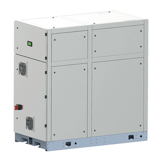
TurboChill™ Chillers Unit Overview Oil Free Centrifugal Compressor Fan Assisted Ventilation Grille Isolator Economiser Image for illustration purposes only TurboChill Water Cooled Technical Manual 9216326 V1.13.0 07_2018... - Page 9 Chillers TurboChill™ Condenser Evaporator TurboChill Water Cooled Technical Manual 9216326 V1.10.0 06_2017...
- Page 10 TurboChill™ Chillers Features The TurboChill Water Cooled Chiller shall be supplied complete with: ● TurboCor Oil Free Compressor ● Microprocessor Control ● Compact Evaporator ● Compact Condenser ● Single Refrigeration Circuit ● Liquid Level Transmitters and Liquid Level Control Valves ●...
-
Page 11: Refrigeration
Chillers TurboChill™ Refrigeration Electronic Expansion Valve Economiser System System Configuration ● ● ● Compact Evaporator with Integrated Sub Cooler ● ● ● Compact Condenser ● ● ● TurboCor Compressor ● – ● R134a Refrigerant – ● – R1234ze(E) Refrigerant ● ●... - Page 12 TurboChill™ Chillers Electronic Expansion Valves (EEV) Electronic expansion valves differ to the normal thermostatic expansion valves in their ability to maintain control of the suction superheat at reduced head pressures. This can lead to significant energy savings particularly at reduced loading and low ambient temperatures.
-
Page 13: Evaporator And Condenser
Chillers TurboChill™ Evaporator and Condenser Condenser Outlet (Supply) Evaporator Outlet (Supply) Condenser Inlet (Return) Evaporator Inlet (Return) Image for illustration purposes only System Configuration ● ● ● Evaporator Differential Pressure Switch ● ● ● Condenser Differential Pressure Switch ● ● ●... -
Page 14: Turbocor Compressor
TurboChill™ Chillers Compressor System Configuration ● ● ● Vibration Isolating Rubber Mounts ● ● ● Suction Strainer ● ● ● Discharge Shut Off Valves ● ● ● Suction Shut Off Valves ● ● ● Line Reactor ● ● ● EMI/EMC Filter –... - Page 15 Chillers TurboChill™ Key benefits of TurboCor compressor technology: ● Oil Free Operation. ● More efficient use of heat exchangers. ● No oil entrainment issues – pipe work can be optimised for performance not oil return. ● Variable speed operation offering exact capacity match and optimum part load performance. ●...
-
Page 16: Waterside
TurboChill™ Chillers Waterside Differential Pressure Sensor Temperature Sensor Shut Off Valve Actuator Image for illustration purposes only System Configuration ● ● ● Differential Water Pressure Transducers* ● ● ● Grooved and Clamped Unit Terminations ● ● ● Manual and Actuated Isolation Valves ●... - Page 17 Chillers TurboChill™ Flow Proving Device* Evaporator and condenser differential pressure sensors facilitate low flow limiting and pressure drop monitoring via the microprocessor which shall be fitted to ensure correct unit water flow. Pump Interlock* Provision for a pump interlock is available within the control panel. Water Flow Switch* If selected, a water flow switch shall be fitted ensuring integrity of the cooling solution flow.
- Page 18 TurboChill™ Chillers Electrical Panel View Filter Reactor Permanent Single Panel Thermostat Phase Supply Comp. Control Board Contactor pCO5+ Controller Isolator 3 Pole MCB Transformer Incoming Controls Incoming Mains Wiring Access Point Supply Permanent 1ph supply (L4) Image for illustration purposes only System Configuration ●...
-
Page 19: Electrical
Chillers TurboChill™ Electrical An electrical power and controls panel is situated at the front of the unit and contains: ● Individual mains power isolator for the compressor ● Emergency interlock isolator handle ● Fully accessible controls compartment, allowing adjustment of control set points whilst the unit is operational ●... -
Page 20: Controls
BMS Interface Cards BMS Interface Card controlled units shall be interfaced with most BMS, factory fitted, please contact Airedale. A wide range of protocols shall be accommodated through the use of interface devices. Available as a standard option are: ModBus/Jbus, and Carel. - Page 21 Chillers TurboChill™ Integrated Optimised Loading and Offloading Sequence A sequence light control algorithm has been integrated into the unit strategy which will allow operation of up to 4 modules (circa 1.5MW). The loading sequence has also been optimised to maximise system EER for a given load, where multiple TCW modules will share the load evenly when possible.
-
Page 22: External
Units shall be supplied complete with additional L.A.T. corner protection and cross braces to afford extra transit protection. Sterling board heat treated man made material shall be used (including pallet) to comply with phytosanity import regulations. (Please contact Airedale for this option). TurboChill Water Cooled Technical Manual 9216326 V1.13.0 07_2018... -
Page 23: Performance Data
Chillers TurboChill™ Performance Data Measurement of Sound Data All sound data quoted has been measured in the third-octave band limited values, using a Real Time Analyser calibrated sound intensity meter in accordance with BS EN ISO 9614 Part 1:2009. The Global sound data quoted is valid for noise emitted in the horizontal plane in all directions. -
Page 24: Design Data
TurboChill™ Chillers Design Data Design Data Glycol Glycol Glycol is recommended when a supply water temperature of +5°C or below is required or when static water can be exposed to freezing temperatures (lower than 3°C Ambient). This is specifi ed further in the environmental consideration section at the front of this document. - Page 25 Chillers TurboChill™ Design Data Glycol Glycol is recommended when a supply water temperature of +5°C or below is required or when static water can be exposed to freezing temperatures (lower than 3°C Ambient). This is specifi ed further in the environmental consideration section at the front of this document.
-
Page 26: Tcw11Rc1E1-Stcw11Rc1E1-Gtcw11Rc1E1-L
TurboChill™ Chillers Technical Data TCW11RC1E1-S - TCW11RC1E1-G - TCW11RC1E1-L Mechanical TCW11RC1E1-L TCW11RC1E1-S TCW11RC1E1-G Cooling Duty Nominal Input 58.19 48.86 67.4 5.16 5.63 5.19 ESEER 7.18 7.85 5.92 Capacity Steps 30-100% 30-100% 30-100% Dimensions (H x W x L) 2000 x 1000 x 1956 2000 x 1000 x 1956 2000 x 1000 x 1956 Machine Weight... - Page 27 Chillers TurboChill™ Technical Data TCW11RC1E1-S - TCW11RC1E1-G - TCW11RC1E1-L Electrical TCW11RC1E1-S-0 TCW11RC1E1-G-0 TCW11RC1E1-L-0 Unit Data Nominal Run Amps Maximum Start Amps Mains Supply 400V (±10%) 3PH 50Hz Rec Mains Fuse Size Max Mains Incoming Cable Size mm² Permanent Supply 230V (±10%) 1PH 50Hz Rec Permanent Fuse Size Max Permanent Incoming Cable Size mm²...
-
Page 28: Tcw11Xc1E1-Stcw11Xc1E1-Gtcw11Xc1E1-L
TurboChill™ Chillers Technical Data TCW11XC1E1-S - TCW11XC1E1-G - TCW11XC1E1-L Mechanical TCW11XC1E1-S TCW11XC1E1-G TCW11XC1E1-L Cooling Duty Nominal Input 58.19 48.86 67.4 5.16 5.63 5.19 ESEER 7.18 7.85 5.92 Capacity Steps 30-100% 30-100% 30-100% Dimensions (H x W x L) 2000 x 1000 x 1956 2000 x 1000 x 1956 2000 x 1000 x 1956 Machine Weight... - Page 29 Chillers TurboChill™ Technical Data TCW11XC1E1-S - TCW11XC1E1-G - TCW11XC1E1-L Electrical TCW11XC1E1-S TCW11XC1E1-G TCW11XC1E1-L Unit Data Nominal Run Amps Maximum Start Amps Mains Supply 400V (±10%) 3PH 50Hz Rec Mains Fuse Size Max Mains Incoming Cable Size mm² Permanent Supply 230V (±10%) 1PH 50Hz Rec Permanent Fuse Size Max Permanent Incoming mm²...
-
Page 30: Waterside Pressure Drop
TurboChill™ Chillers Waterside Pressure Drop Evaporator Flowrate l/s Condenser Flowrate l/s Graphs represent performance at 100% water. TurboChill Water Cooled Technical Manual 9216326 V1.13.0 07_2018... -
Page 31: Minimum System Water Volume Calculations
Chillers TurboChill™ Minimum System Water Volume Calculations METHOD 1 (Preferred Method) Where the system permanent heat load is known, the minimum water volume in litres V = Water Flow Rate (litres/min) x Minimum Compressor Run Time (min) x Chiller Loading Factor (CLF) Where Vmin is the minimum water volume in llitres Minimum Compressor Run Time is 2 minutes... -
Page 32: Installation Data
● Lift the unit slowly and evenly ● If the unit is dropped, it should immediately be checked for damage and reported to Airedale Service CAUTION Only use lifting points provided. The unit should be lifted from the base and where possible, with all packing and protection in position. If any other type of slinging is used, due care should be taken to ensure that the slings do not crush the casework. -
Page 33: Centre Of Gravity
Chillers TurboChill™ Installation Data Centre of Gravity Lifting Operating CoG 1 CoG 2 Lifting CoG Mass Mass 2253 2465 1225 1220 TCW11RC1E1-S 2265 2477 1220 1220 TCW11RC1E1-G 2265 2477 1220 1220 TCW11RC1E1-L TCW11XC1E1-S 2358 2570 1215 1220 2370 2582 1215 1220 TCW11XC1E1-G 2370... -
Page 34: Dimensions
TurboChill™ Chillers Dimensions TurboChill Water Cooled Technical Manual 9216326 V1.13.0 07_2018... -
Page 35: Module Installation
Chillers TurboChill™ Module Installation The compact evaporator and condenser shall be designed for a single refrigeration circuit. The compact design lends itself to a modular application as can be seen below. Multiple Modules TCW Module removal/installation Each module shall be a complete packaged water cooled chiller independent of adjacent modules; multiple modules can be linked together via a common waterside to increase plant capacity as required. - Page 36 TurboChill™ Chillers Clearance Should the chiller be installed standalone/unable to move the unit, provison must be made for maintenance around the chiller. The following minimum clearance is required: Pipework Pipework Start position Finish Position Units unable to move Moveable A - Clearance between units - 800mm B - Clearance between unit and external walls - 800mm C - Clearance for chiller - 2000mm D - Clearance for chiller maneuverability - 3000mm...
-
Page 37: Standard Recommended Pipework Installation
VALVES OFF VALVES PUMP AERATER Supplied by Others Supplied by Airedale PUMP (Optional Extra) STRAINER Condenser Head Pressure Control To ensure correct operation of the chiller a 3-way mixing valve shall be installed on the condenser supply water leg. The aim is to maintain the design head pressure setpoint throughout the operation of the chiller at various loading stages and ambient conditions. -
Page 38: Pressure Relief Valve Discharge Piping
TurboChill™ Chillers Pressure Relief Valve Discharge Piping Considerations must be made when designing pipework for PRV venting. This must be designed in accordance to EN378-3 Section 5.8 Piping and ducting. Caution must be taken to ensure excessive pressure drop in the pipework is avoided. ●... -
Page 39: Differential Pressure Connections
Chillers TurboChill™ Differential Pressure Connections DETAIL A The 1/4” BSP Male connection to the water pipework shall be connected through the bulkhead of IMPORTANT the unit. Trace heating must be applied to protect against freezing. TurboChill Water Cooled Technical Manual 9216326 V1.10.0 06_2017... -
Page 40: Water System
TurboChill™ Chillers Water System Component Recommended Requirements The recommended requirements to allow commissioning to be carried out correctly are: ● The inclusion of binder points adjacent to the flow and return connections, to allow temperature and pressure readings ● A differential pressure sensor or equivalent, fitted adjacent to the water outlet side of the unit ●... - Page 41 Chillers TurboChill™ Pump Statement When installing circulating water pumps or equipment containing them, the following rules should be applied: ● Ensure the system is filled with liquid then vented and the pump primed with water before running the pump, this is required because the pumped liquid cools the pump bearings and mechanical seal faces ●...
-
Page 42: Electrical
TurboChill™ Chillers Electrical ● Please refer to the electrical wiring diagrams provided for installation. ● ALL work MUST be carried out by technically trained competent personnel. ● The equipment contains live electrical and moving parts, ISOLATE prior to maintenance or repair work. -
Page 43: Interconnecting Wiring
Chillers TurboChill™ Interconnecting Wiring ¡ ç ¡ ç Mains Incoming Supply 400V / 3~ / 50Hz ¡ ç ¡ ç ¡ ç Separate Permanent Supply ¡ ç 230V / 1~ / 50Hz ¡ ç ¡ è (1) Evaporator Flow Switch ¡... -
Page 44: Plan Termination
TurboChill™ Chillers pLAN Termination Customer Side The plugged termination ensures that the connections are made simultaniously. Failure to attached the cables this this way may cause damage to the controller. RxTx - RxTx + RxTx - RxTx + Sensor Connections Panel Side 3-WAY VALVE... -
Page 45: Power Quality & Harmonics
Chillers TurboChill™ Power Quality & Harmonics Variable speed drives are now common place due to their efficiency and versatility. Not ignoring these facts, care must be taken when installing VSD technology into new and existing installations. This is due to the effect the introduction of such technology may have on line harmonics of a buildings electrical system. -
Page 46: Commissioning
TurboChill™ Chillers Commissioning To be read in conjunction with the commissioning sheets provided. Please ensure all documents have been completed correctly and return to Airedale Technical CAUTION Support immediately to validate warranty. Pre Commissioning Checklist CAUTION ALL work MUST be carried out by technically trained competent personnel. - Page 47 Chillers TurboChill™ ● With the unit running increase the low temperature limit to the actual supply water temperature - this will trip the unit in a safe manner without risk of freezing the evaporator ● Return the low temperature limit to correct value after test (this will allow the unit to operate correctly) Pump Interlock The pump interlock is fitted and functioning correctly.
- Page 48 TurboChill™ Chillers Refrigeration Compressor Record on the commissioning sheet compressor details ● Type ● Serial numbers ● Overload settings Operating Conditions Record the following operating conditions of the unit at stable conditions: ● Suction pressure (Bar) ● Liquid pressure (Bar) ●...
-
Page 49: Maintenance
Pressure Relief Valve In line with EN 378, Airedale recommends that the valve be replaced at least every 5 years. These intervals may have to be reduced if other regulations apply. The pressure relief is fitted to the unit by a three way dual shut off valve. - Page 50 TurboChill™ Chillers Maintenance Check the following against commissioning records. Investigate and adjust as necessary. Frequency Task 3 months 12 months 60 months Check the following against commissioning records: Alarm log for unusual occurrences Chilled water control maintains design termperatures ...
- Page 51 Anti-vibration mounts fixings (if fitted) Check operation of discharge non return valve For further information refer to compressor manual which is available from Airedale on request or the TurboCor website. Change the compressor capacitor Change the controller battery (may be more frequent ...
-
Page 52: Troubleshooting
TurboChill™ Chillers Troubleshooting FAULT POSSIBLE CAUSE REMEDY/ACTION No power. Check power supply to the controller. Check wire connections in accordance with wiring Wired incorrectly. Unit will not start diagram. Loose wires. Check all wires, connections, terminals etc. Remote on/off. Check that the remote on/off is at the on position. Check isolator, fuses, MCBs, contactor and control circuit No power to compressor. -
Page 53: Storage Recommendations
TurboChill™ Storage Recommendations Airedale recommends that equipment should be stored in an ambient protected warehouse facility. The unit should be stored within a heated warehouse ensuring that the temperature does not fall below 0°C. All water should be drained from the evaporator and condenser. Ensure refrigerant line shut off valves are closed. -
Page 54: After Sales
All Airedale products or parts (non consumable) supplied for installation within the UK mainland and commissioned by an Airedale engineer, carry a full Parts & Labour warranty for a period of 12 months from the date of commissioning or 18 months from the date of despatch, whichever is the sooner. -
Page 55: Appendix - Ecodesign
Chillers TurboChill™ Appendix - Ecodesign The following tables of Ecodesign data is based on the following common information: SEPR (Seasonal Energy Performance Ratio) ● Type of Condensing - Water Cooled. ● Refrigerant Fluid - R134a / R1234ze. ● Operating Temperature - +7°C (Outlet water). ●... -
Page 56: Tcw11Rc1E1-Stcw11Rc1E1-Gtcw11Rc1E1-L
TurboChill™ Chillers Technical Data TCW11RC1E1-S - TCW11RC1E1-G - TCW11RC1E1-L Ecodesign TCW11RC1E1-S Notes: Units TCW11RC1E1-G TCW11RC1E1-L SEPR 1,3,5 9.23 9.31 8.72 SEPR Tier Tier 2 (2021) Tier 2 (2021) Tier 2 (2021) Annual Electricity Consumption kWh/a 218317 296247 240181 Rated Refrigerant Capacity P 1,3,5 299.1 274.3... -
Page 57: Tcw11Xc1E1-Stcw11Xc1E1-Gtcw11Xc1E1-L
Chillers TurboChill™ Technical Data TCW11XC1E1-S -TCW11XC1E1-G -TCW11XC1E1-L Ecodesign Notes: Units TCW11XC1E1-S TCW11XC1E1-G TCW11XC1E1-L SEPR 1,3,5 9.23 9.31 8.72 SEPR Tier Tier 2 (2021) Tier 2 (2021) Tier 2 (2021) Annual Electricity Consumption kWh/a 218317 296247 240181 Rated Refrigerant Capacity P 1,3,5 299.1 274.3... - Page 58 TurboChill™ Chillers TurboChill Water Cooled Technical Manual 9216326 V1.13.0 07_2018...
- Page 59 Head Office Airedale International Air Conditioning Ltd Leeds Road Rawdon Leeds LS19 6JY Tel: +44 (0) 113 2391000 Fax:+44 (0) 113 2507219 E-mail enquiries@airedale.com Web www.airedale.com...
Need help?
Do you have a question about the TurboChill TCW and is the answer not in the manual?
Questions and answers