
Related Manuals for JCM GEN5 Series


Summary of Contents for JCM GEN5 Series
- Page 1 Website: http://www.jcmglobal.com GEN5 ™ Series Printer Operation and Maintenance Manual (Revision A) P/N 960-100940R_Rev. A © 2016, JCM American Corporation...
-
Page 2: Revision History
2. When an end user duplicates the Manual to maintain operation of the product or operate the product in general. JCM retains all rights to amend, alter, change or delete any portion of this Manual in whole, or in part, or add items ... -
Page 3: Table Of Contents
Europe, Middle East, Africa & Russia ................. 1-11 JCM Europe GmbH ........................ 1-11 UK & Ireland ....................... 1-11 JCM Europe (UK Office) ......................1-11 Asia and Oceania ....................... 1-11 JCM Gold (HK) LTD........................ 1-11 JAPAN CASH MACHINE CO., LTD. (HQ) ................1-11 2 INSTALLATION .................... - Page 4 Europe, Middle East, Africa & Russia ................3-1 JCM Europe GmbH ......................... 3-1 UK & Ireland ......................... 3-1 JCM Europe (UK Office) ......................3-1 Asia and Oceania ......................3-1 JCM Gold (HK) LTD......................... 3-1 JAPAN CASH MACHINE CO., LTD. (HQ) ................3-1 4 DISASSEMBLY/REASSEMBLY .................
- Page 5 GEN5™ Series Printer Table of Contents Page Firmware Download Procedure ..................6-3 JCM Printer Driver Installation .................. 6-4 Running the JCM Printer Basic Driver ................6-4 Printer Basic Driver Main Page ..................6-5 Printer Configuration ........................6-5 Commands ..........................6-5 Printer Status ..........................6-6 Menu Options ...........................6-6...
- Page 6 GEN5™ Series Printer THIS PAGE INTENTIONALLY LEFT BLANK P/N 960-100940R_Rev. A © 2016, JCM American Corporation...
- Page 7 Figure 4-15 Remove Lower Idler Roller ..............4-5 Figure 4-16 Remove Motor Mounting Bracket ............4-5 Figure 4-17 Remove Snap Rings Left ..............4-5 Figure 4-18 Remove Snap Rings Right ..............4-5 P/N 960-100940R_Rev. A © 2016, JCM American Corporation...
- Page 8 Figure 6-12 Start Full Firmware Upgrade ..............6-4 Figure 6-13 Firmware Upgrade Completed .............. 6-4 Figure 6-14 JCM Printer Basic Driver UI ..............6-5 Figure 6-15 Connecting to Selected Port Message........... 6-5 Figure 6-16 Printer Basic Driver Main Page ............. 6-5 Figure 6-17 Printer Configuration Section ..............
- Page 9 Table A-2 Front Bezel LED Indicators (Printer Status) ..........A-2 Table A-3 Printer Status LED Codes ..............A-2 Table A-4 Printer Error Conditions ................ A-3 Table A-5 Additional Maintenance Equipment Parts List ........A-4 P/N 960-100940R_Rev. A © 2016, JCM American Corporation...
- Page 10 GEN5™ Series Printer THIS PAGE INTENTIONALLY LEFT BLANK P/N 960-100940R_Rev. A © 2016, JCM American Corporation viii...
-
Page 11: Gen5™ Series
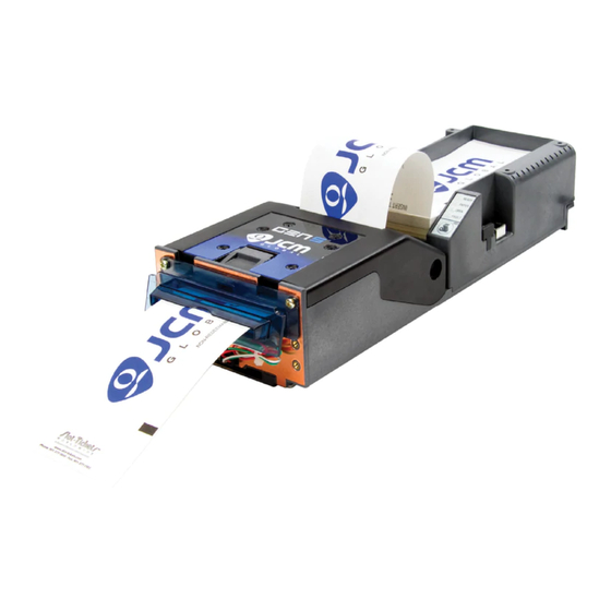
Steps require the operator to perform specific • Specifications actions; these are identified with sequential • Unit Dimensions numbers (1, 2, 3, etc.). • Technical Contact Information GEN5 Printer Unit Figure 1-1 GEN5 Printer Unit P/N 960-100940R_Rev. A © 2016, JCM American Corporation 1 - 1... -
Page 12: Product Descriptions
7. Clean and maintain the Printer regularly when Type 1 Type 2 Type 3 located in an excessively smoke-filled environ- ment. Figure 1-2 Precautionary Symbols P/N 960-100940R_Rev. A © 2016, JCM American Corporation 1 - 2... -
Page 13: Mounting, Dismounting & Transportation
3. Clean the Unit once a month to keep its perfor- mance stable. P/N 960-100940R_Rev. A © 2016, JCM American Corporation 1 - 3... -
Page 14: Ticket Fitness Requirements
TITO and Promotional Tickets • Blocked Bezel Jam Prevention Technology – detection prevents jamming • Compatibility with all Game Manufacturers’ USB, RS232C and Netplex Products – Communications are available on all Units. P/N 960-100940R_Rev. A © 2016, JCM American Corporation 1 - 4... -
Page 15: Component Names
DIP Switch (under Rubber Boot) d) Copper Shield k) USB Update Port e) Bezel LED Connector l) Paper Tray (300 note) f) Bottom Tray Figure 1-4 GEN5 Printer Components P/N 960-100940R_Rev. A © 2016, JCM American Corporation 1 - 5... -
Page 16: Specifications
USB 2.0 (Full Speed at 12Mbps); USB Download Port; Communications: Compliant with GSA GDS, IGT USB/Netplex, RS-232C *. Template Storage and Graphic Storage use shared memory. P/N 960-100940R_Rev. A © 2016, JCM American Corporation 1 - 6... -
Page 17: Environmental Specifications
*. Power Supply should be UL Listed or IEC Certified and marked “Class 2” or “LPS”. Structural Specifications Table 1-7 GEN5 Structural Specifications Weight: Approximately 1.22kg (2.7lbs.) Mounting: Horizontal Outside Dimensions: See “Entire Unit Outside Dimensions” on page 1-9 P/N 960-100940R_Rev. A © 2016, JCM American Corporation 1 - 7... -
Page 18: Ticket Specifications
MAX AREA FOR PRE-PRINTED GRAPHIC IMAGES 10.16 WHITE GAP STAY OUT AREA 1.51 MAX 5.08 31.74 156 ± 1 NOTE: All dimensions in millimeters Figure 1-5 GEN5 Printer Unit Ticket Specifications P/N 960-100940R_Rev. A © 2016, JCM American Corporation 1 - 8... -
Page 19: Unit Dimensions
92.99 68.53 306.71 Optional Paper Trays require additional clearance. NOTE: All dimensions in millimeters Figure 1-6 GEN5 Printer Unit With 300-Note Paper Tray (Without Bezel) Outside Dimensions P/N 960-100940R_Rev. A © 2016, JCM American Corporation 1 - 9... -
Page 20: Entire Unit Outside Dimensions (Continued)
Printer Unit must be mounted to a grounded metal plate 8xØ6.35 8xØ4.57 31.75 19.05 88.9 19.05 203.2 19.05 231.78 19.05 291.97 NOTE: All dimensions in millimeters Figure 1-7 GEN5 Printer Unit Mounting Rail Dimensions P/N 960-100940R_Rev. A © 2016, JCM American Corporation 1 - 1 0... -
Page 21: Technical Contact Information
JAPAN E-mail: support@jcmglobal.eu E-mail: Shohin@jcm-hq.co.jp UK & Ireland JCM Europe (UK Office) Phone: +44 (0) 190-837-7331 The JCM website for all locations is: http://www.jcmglobal.com Fax: +44 (0) 190-837-7834 Unit B, Third Avenue Denbigh West Business Park Bletchley, Milton Keynes, Buckinghamshire MK1 1DH, UK E-mail: support@jcmglobal.eu... - Page 22 Section 1 GEN5™ Series Printer General Information THIS PAGE INTENTIONALLY LEFT BLANK P/N 960-100940R_Rev. A © 2016, JCM American Corporation 1 - 1 2...
-
Page 23: Installation
† Mode (bps 9600 9600 19200 38400 (Default) 57600 115200 307200 921600 XON/XOFF (SW) *. DIP Switches SW5 and SW6 are NOT USED. †. bps = bits per second. P/N 960-100940R_Rev. A © 2016, JCM American Corporation 2 - 1... -
Page 24: Manual Baud Rate Setting
3 seconds. If the GREEN Ready light flashes, the Paper Low Sensor has just been turned ON. If the RED Fault light flashes, the Paper Low Sensor has just been turned OFF. P/N 960-100940R_Rev. A © 2016, JCM American Corporation 2 - 2... -
Page 25: Connector Pin Assignments
Ground USB- USB- (N) +13V No Connection Switched+24V Switched 24V Bezel Data Terminal Ready MRESET Master Reset USB+ USB+ (P) +24V DC +24V DC Power Supply Request to Send P/N 960-100940R_Rev. A © 2016, JCM American Corporation 2 - 3... -
Page 26: Rs232C Connector Pin Assignments
+24V DC Power Supply DGND Ground +24V DC +24V DC Power Supply Switched +24V Switched +24V(Bezel) DGND Ground Receive 1 - RS232C Transmit 1 - RS232C DATA Terminal Ready Request to Send P/N 960-100940R_Rev. A © 2016, JCM American Corporation 2 - 4... -
Page 27: Bezel Connector (On Coil Harness) Pin Assignments
Table 2-8 GEN5 Auxiliary Port Connector Pin Assignments USB Coil Interface Connector (2nd Port Harness) Connector: 39-01-3042 Mini-Fit Jr. (MOLEX) Pin No. Signal Name Function DGND GROUND RX2 232C TX2 232C No Connection P/N 960-100940R_Rev. A © 2016, JCM American Corporation 2 - 5... -
Page 28: Preventive Maintenance
Section 2 GEN5™ Series Printer Installation Preventive Maintenance JCM strongly recommends regularly scheduled Preventive Maintenance procedures to ensure that the GEN5 Printer performance meets factory speci- fications for trouble-free operation. Loading Tickets To load tickets into the GEN5 Printer, perform the following steps: 1. -
Page 29: Clearing A Ticket Jam
Cleaning Procedure red arrow (Figure 2-6 a) to access the Printer interior (Figure 2-6 b). JCM strongly recommends an annual completion of the Cleaning and Preventive Maintenance proce- dures to ensure that the GEN5 Printer performance meets factory specifications for trouble-free opera- tion. -
Page 30: Sensors Cleaning Procedure
(Paper Low) alcohol swab. Paper Out Blow clean with (Index Mark) Compressed Air Wipe clean with an Lid Open alcohol swab. Wipe clean with an Taken Sensor alcohol swab. P/N 960-100940R_Rev. A © 2016, JCM American Corporation 2 - 8... -
Page 31: Cleaning Card Cleaning Procedure
NOTE: Each Cleaning Card is intended for single use only. Always use a new Cleaning Card for each cleaning cycle. 8. Feed 2 or 3 Tickets through the Printer to remove alcohol residue. P/N 960-100940R_Rev. A © 2016, JCM American Corporation 2 - 9... - Page 32 Section 2 GEN5™ Series Printer Installation THIS PAGE INTENTIONALLY LEFT BLANK P/N 960-100940R_Rev. A © 2016, JCM American Corporation 2 - 1 0...
-
Page 33: Communications
2-3-15, Nishiwaki, Hirano-ku, Osaka 547-0035 JAPAN D-40472 Düsseldorf Germany E-mail: Shohin@jcm-hq.co.jp E-mail: support@jcmglobal.eu UK & Ireland The JCM website for all locations is: JCM Europe (UK Office) http://www.jcmglobal.com Phone: +44 (0) 190-837-7331 Fax: +44 (0) 190-837-7834 Unit B, Third Avenue... - Page 34 Section 3 GEN5™ Series Printer Communications THIS PAGE INTENTIONALLY LEFT BLANK P/N 960-100940R_Rev. A © 2016, JCM American Corporation 3 - 2...
-
Page 35: Disassembly/Reassembly
Figure 4-1 Remove Paper Tray Mounting Screws 2. Lift the Paper Tray up slightly, then disconnect the LED panel connection (not shown). 3. Lift the Paper Tray up and off the Bottom Tray. P/N 960-100940R_Rev. A © 2016, JCM American Corporation 4 - 1... -
Page 36: Print Mechanism Disassembly
3. Pull the Hinge Pin (Figure 4-4 b) out of the side of the Print Head, separating the Mounting Bracket from the Lid Assembly. 4. Remove four (4) screws securing the Print Head (Figure 4-4 thru P/N 960-100940R_Rev. A © 2016, JCM American Corporation 4 - 2... -
Page 37: Upper Presenter Motor Removal
5. Remove four (4) flat head screws holding the left side (Figure 4-9 thru ) and the single Pan Head screw from the inside of the left bracket (Figure 4-9 e). P/N 960-100940R_Rev. A © 2016, JCM American Corporation 4 - 3... -
Page 38: Bottom Presenter Mechanism Disassembly
Taken Sensor (Figure 4-12 b). 2. Remove one (1) connector (Figure 4-12 c). 3. Lift the Taken Sensor off the Bottom Presenter. Figure 4-14 Remove Presenter Motor Figure 4-12 Remove Taken Sensor P/N 960-100940R_Rev. A © 2016, JCM American Corporation 4 - 4... -
Page 39: Presenter Rollers
8. Remove the four (4) Roller Bushings (2 Left/2 Right) (Figure 4-19 thru 9. Remove the two (2) Presenter Rollers (Figure 4- Figure 4-16 Remove Motor Mounting Bracket Figure 4-19 Remove Roller Bushings and Presenter Rollers P/N 960-100940R_Rev. A © 2016, JCM American Corporation 4 - 5... - Page 40 Section 4 GEN5™ Series Printer Disassembly/Reassembly THIS PAGE INTENTIONALLY LEFT BLANK P/N 960-100940R_Rev. A © 2016, JCM American Corporation 4 - 6...
-
Page 41: Wiring Diagrams
5 WIRING DIAGRAMS This section provides the following Wiring • System Wiring Diagram. Diagram for the GEN5 Printer Unit: System Wiring Diagram Figure 5-1 GEN5 Printer System Wiring Diagram P/N 960-100940R_Rev. A © 2016, JCM American Corporation 5 - 1... - Page 42 Section 5 GEN5™ Series Printer Wiring Diagrams THIS PAGE INTENTIONALLY LEFT BLANK P/N 960-100940R_Rev. A © 2016, JCM American Corporation 5 - 2...
-
Page 43: Firmware Updating And Testing
System Resources Paper Low Detect: Enabled Disabled Library Inventory SYSTEM RESOURCES (Fonts) Amount of Flash Flash-Used: 000016 Memory in use Flash Memory Free: 524256 Available Figure 6-2 Configuration Ticket (sample) P/N 960-100940R_Rev. A © 2016, JCM American Corporation 6 - 1... -
Page 44: Printing A Configuration Ticket
Figure 6-3 Load Ticket Stack into Printer/ LED Status Figure 6-5 FLDFUSetupV228.exe File Location Welcome to the InstallShield Wizard for The “ FLIDFU Downloader ” Screen shown in Figure 6-6 will appear. P/N 960-100940R_Rev. A © 2016, JCM American Corporation 6 - 2... -
Page 45: Firmware Download Procedure
FLDFU Downloader “ ” top to launch the applica- tion. 4. Look for verification of a valid connection to the GEN5 Printer (Figure 6-11 a). Figure 6-8 Installing FLIDFU Downloader P/N 960-100940R_Rev. A © 2016, JCM American Corporation 6 - 3... -
Page 46: Jcm Printer Driver Installation
“ ” file to install the application. Running the JCM Printer Basic Driver To run the JCM Printer Basic Driver Application: Start 1. Click the button on the PC desktop. Figure 6-12 Start Full Firmware Upgrade Programs JCM. -
Page 47: Printer Basic Driver Main Page
Printer (Figure 6-16) will be Basic Driver Main Page displayed. Figure 6-14 JCM Printer Basic Driver UI 4. Select the desired Communication Protocol and Port Number to connect the Printer. Figure 6-16 Printer Basic Driver Main Page a) To toggle the Communication Protocol setting from... -
Page 48: Printer Status
Printer’s current status. When any of the twenty Exiting the Printer Driver Application (20) separate Warning conditions monitored by the To close and exit the JCM Basic Printer Driver user Printer occurs, the Warning tile display color interface, click the Close icon (Figure 6-21 a). -
Page 49: Exploded Views & Parts Lists
GEN5 Entire Unit Exploded View • GEN5 Bottom Tray Assembly Exploded View • GEN5 Bottom Presenter Exploded View GEN5 Entire Unit Exploded View Figure 7-1 GEN5 Entire Unit Exploded View P/N 960-100940R_Rev. A © 2016, JCM American Corporation 7 - 1... -
Page 50: Gen5 Entire Unit Parts List
140-00243-102 PCBA Assy., GEN5 370-00015-100 Base 150-00373-100 Cable Assy., Coil 14 RS232/USB 362-00253-100 Label, Tray JCM Arrow 362-00256-100 Label, Lid, JCM Type 5 362-00080-101 Label, No Tamper 473-00082-100 SCR,FLHPH,PLASTITE 48-2,#6x3/8 473-00117-100 STUD, SELF CLINCHING PEM FHS-632-8 OR EQ. 476-00008-100 NUT, HX, #6-32, Narrow. -
Page 51: Gen5 Bottom Presenter Exploded View
Exploded Views & Parts Lists GEN5™ Series Printer Section 7 GEN5 Bottom Presenter Exploded View Figure 7-2 GEN5 Bottom Presenter Exploded View P/N 960-100940R_Rev. A © 2016, JCM American Corporation 7 - 3... -
Page 52: Gen5 Bottom Presenter Parts List
473-00050-100 Screw, MACH, PNHPH 4-40x0.187 482-00012-100 Washer, Lock Motor 486-00044-100 Retaining Ring, 0.188 473-00078-100 Screw, PLASTITE PNHPH #4x0.25 150-00033-100 Ground Harness 150-00027-100 Cable, Assy-Taken Sensor 482-00028-100 Washer #6 473-00079-100 Screw, PLASTITE 48-2, #6x0.25 P/N 960-100940R_Rev. A © 2016, JCM American Corporation 7 - 4... -
Page 53: Gen5 Bottom Presenter Housing Exploded View
Exploded Views & Parts Lists GEN5™ Series Printer Section 7 GEN5 Bottom Presenter Housing Exploded View Figure 7-3 GEN5 Bottom Presenter Housing Exploded View P/N 960-100940R_Rev. A © 2016, JCM American Corporation 7 - 5... -
Page 54: Gen5 Bottom Presenter Housing Parts List
GEN5 Bottom Presenter Housing Parts List Table 7-3 GEN5 Bottom Presenter Housing Parts List Ref No. Part No. Description Remark 470-00007-100 Lid Sensor 473-00099-100 Screw, PNHPH 2-32x0.125 486-00032-100 Bearing, Plastic 486-00044-100 Retaining Ring P/N 960-100940R_Rev. A © 2016, JCM American Corporation 7 - 6... -
Page 55: Gen5 Top Presenter Exploded View
Exploded Views & Parts Lists GEN5™ Series Printer Section 7 GEN5 Top Presenter Exploded View Figure 7-4 GEN5 Top Presenter Exploded View P/N 960-100940R_Rev. A © 2016, JCM American Corporation 7 - 7... -
Page 56: Gen5 Top Presenter Parts List
Ref No. Part No. Description Remark 370-00019-100 Top Presenter 370-00021-100 Floating Part 370-00026-100 Floating Part, Cover Plate - Spring 485-00175-100 Spring, Compression 460-00006-100 Roller, Pinch 473-00078-100 Screw, PLASTITE, PNHPH #4x0.25 P/N 960-100940R_Rev. A © 2016, JCM American Corporation 7 - 8... -
Page 57: Gen5 Lid Upper Presenter Exploded View
Exploded Views & Parts Lists GEN5™ Series Printer Section 7 GEN5 Lid Upper Presenter Exploded View Ground Lug From Bottom Presentor Figure 7-5 GEN5 Lid Upper Presenter Exploded View P/N 960-100940R_Rev. A © 2016, JCM American Corporation 7 - 9... -
Page 58: Gen5 Lid Upper Presenter Parts List
486-00033-100 Retaining Ring, Hinge Pin, E-RING 0.25in. dia. 473-00082-100 Screw, Top Presenter, PLASTITE-FLHPH #6x.375 482-00012-100 Washer, Lock 485-00008-100 Spring, Compression 473-00078-100 Screw, PLASTITE-PNHPH #4x.025 150-00023-100 Print Head Harness P/N 960-100940R_Rev. A © 2016, JCM American Corporation 7 - 1 0... -
Page 59: Gen5 Bottom Tray Assembly Exploded View
Exploded Views & Parts Lists GEN5™ Series Printer Section 7 GEN5 Bottom Tray Assembly Exploded View Figure 7-6 GEN5 Bottom Tray Assembly Exploded View P/N 960-100940R_Rev. A © 2016, JCM American Corporation 7 - 1 1... -
Page 60: Gen5 Bottom Tray Assembly Parts List
473-00019-103 SCR, MACH PNHPH, M3x4mm Screw Lock Spring 473-00072-100 SCR, SHLDR 4-40 1/8 x 3/16 473-00497-100 SCR, MACH PN# 9PH #2 x 3/16 485-00019-100 SPR - EXT 150-00028-100 CABLE, ASSY. BEZEL 486-00001-100 WIRE SADDLE NYLON P/N 960-100940R_Rev. A © 2016, JCM American Corporation 7 - 1 2... -
Page 61: Index
Instructions for ...A-1 GEN5 photo of a ...1-1 Wiring Diagram system & individual primary part ...5-1 Model Descriptions Product Number Specifications of ...1-2 Navigation within manual ...1-1 procedure for © 2016, JCM American Corporation P/N 960-100940R_Rev. A 8 - 1... - Page 62 GEN5™ Series Printer THIS PAGE INTENTIONALLY LEFT BLANK © 2016, JCM American Corporation P/N 960-100940R_Rev. A 8 - 2...
-
Page 63: A Troubleshooting
Refer to Section 6: “Firmware Updating and Testing” on page 6-1 for details. Ticket does not load Reload the ticket. Refer to “Clearing a Ticket Jam” on page 2-7 for details. P/N 960-100940R_Rev. A © 2016, JCM American Corporation A - 1... -
Page 64: Led Indication Conditions
Ready (GREEN) Paper (YELLOW) Open (ORANGE) Fault (RED) No Power Ready No Ticket Detected Paper Jam Detected Printer Lid Open Firmware Problem Detected Hardware Fault Detected *. LED Flashes P/N 960-100940R_Rev. A © 2016, JCM American Corporation A - 2... -
Page 65: Printer Errors
The Printer will remain in this condition until the power is cycled or the Unit problem with the Thermal Print Print Head is reset. If the problem persists, the Printer may require service. Contact JCM Head. This condition may occur Customer Service for assistance. -
Page 66: Maintenance Equipment
JAC No. Description Qty. Remark 150-00013-100 Evaluation Cable 350-00258-100 Power Supply/With AC Plug 400-100249R USB Cable A-B 302-100004R USB Serial Adapter 30210001012 JU-H40911-S1 4 Port HUB 150-00373-100 Coil Harness P/N 960-100940R_Rev. A © 2016, JCM American Corporation A - 4... -
Page 67: B Glossary
... 6-1 Pictograph small internationally recognized safety and attention symbols placed to the left of Notes, Cautions and Warnings throughout a JCM Maintenance Manual ... 1-1 Precautions Special instructions and warnings that appear in JCM Maintenance Manuals. Precau- tions are intended to promote personal safety and prevent damage to equipment when working with the applicable JCM Product ... - Page 68 Host controller, and is commonly found on nearly all personal comput- ers built today. The GEN5 Printer features a USB interface, allowing the user to download data files into flash memory quickly and easily from a PC ... 2-5 P/N 960-100940R_Rev. A © 2016, JCM American Corporation B - 2...
- Page 70 GEN5™ Series Printer P/N 960-100940R_Rev. A © 2016, JCM American Corporation...
Need help?
Do you have a question about the GEN5 Series and is the answer not in the manual?
Questions and answers