Table of Contents
Advertisement
Quick Links
Advertisement
Table of Contents

Related Manuals for JCM TSP - 02


Summary of Contents for JCM TSP - 02
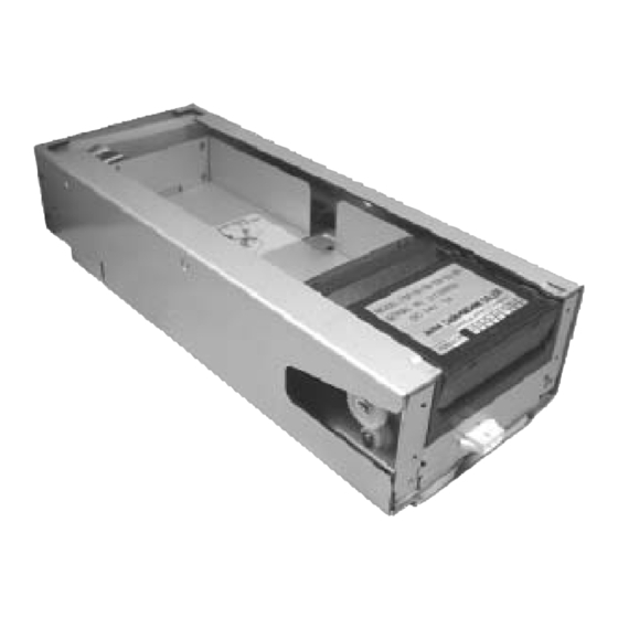
- Page 1 Office: (800) 683-7248 Technical Support: (702) 651-3444 FAX: (702) 651-0214 E-Mail: techsupport@jcm-american.com Web-Site: www.jcm-american.com TSP - 02 Printer Operation and Maintenance Manual (Rev. B) JCM Part No. 960-000051 2004 JCM – American, Corp.
-
Page 3: Table Of Contents
Table of Contents Introduction......................... 1 Model Classification ......................2 General Specifications ......................3 Installation .......................... 5 Loading Paper ........................6 Pin Assignments ......................... 7 Dip Switch Settings ......................8 Maintenance ........................10 Sensor Adjustment ...................... 10 Cleaning ........................10 Exploded View ......................... 11 Parts List ........................... -
Page 5: Introduction
Introduction The TSP - 02 Printer The TSP – 02 printer is a multipurpose while allowing the customer the freedom to thermal printer that is suitable for any create a unique 4-color design on the top application requiring quality printing ability. -
Page 6: Model Classification
600 notes (with extended hopper) (5) Paper size Fanfold paper, 65 mm x 156 mm (US $ size) (6) Faceplate No Faceplate (7) Type of Software ID-003 JCM Standard ID-024 IGT Netplex (8) Other Options 001 – Standard configuration Examples: TSP-02-05-310-03-001 Printer model 02 with no front bracket, small rear style mounting, 003 ribbon style cable;... -
Page 7: General Specifications
Recommended Thermal Paper Brand - Kanzaki Part No. TO-381N NOTE: Using paper not recommended may affect quality and thermal printer head longevity. Contact your JCM account representative for a list of qualified suppliers. Paper Dimensions 65 mm width 156 mm Length... - Page 8 General Specifications: Con’t Installation Indoors Avoid direct sunlight A lengthwise installation angle between 0 and 45 Angle Operating Environment Temperature : C ~ +45 C (41 F ~ 113 Humidity : 10 ~ 90% RH (no condensation) Storage Environment Temperature : C ~ +70 C (77 F ~ 158...
-
Page 9: Installation
Installation... -
Page 10: Loading Paper
Loading Paper Set the packet of fan-folded paper beside the printer, making sure the Index mark is positioned properly. Remove the band from the packet and drop it in the printer hopper. Turn the printer ON. Place the top sheet of paper in the entry opening as shown in photo. -
Page 11: Pin Assignments
Pin Assignments a. Pin Assignments (Main connector on underside of printer) Position Name Description MRESET Hardware reset RXD - I Receive data (printer), Photo-coupler Isolation Photo-coupler bias voltage. (DC+12 V or DC+13 V) TXD – I Transmit data (printer), Photo-coupler Isolation IGND Isolated Ground DC+24 V... -
Page 12: Dip Switch Settings
Dip Switch Settings DIP Switches DIP Switch 1 2 3 4 Function 0 0 0 0 Normal operation (interfaced with a host controller) 1 0 0 0 Reserved 0 0 0 1 Ticket print test 1 0 0 1 Continuous ticket print test 0 1 0 1 Reserved 1 1 0 1... - Page 13 Continuous Ticket Printer Test - Printer will print one ticket after another (Previously printed ticket does not have to be removed.). Sensor Adjustment Data - Mark sensor and Exit sensor adjustment data is printed on ticket. Test Pattern and Version Information - A checker pattern, model name and version information is printed on ticket.
-
Page 14: Maintenance
Maintenance Sensor Adjustment Procedure • Make sure printer power is turned off • Turn ON all four DIP switches • Open the printer and insert the reference paper (Part No. 501-000059) • Turn on printer power • Wait for the LED to flash (On - 100ms, Off - 1 sec.). You may need to wait 10 seconds •... -
Page 15: Exploded View
Exploded View... -
Page 16: Parts List
Part No. Description Qty. 079520 Slide Frame 079526 Slide Guide (L) 079527 Slide Guide (R) 079575 I/F Assy. 079574 Slide Harness 079530 Harness Clamp 079517 Unit Base 079533 079519 Unit Lock 079538 Unit Lock Spring 079537 Unit Lock Bush 005663 Clamp 079576 Sensor Assy. - Page 17 Part No. Description Qty. 072284 Switch Insulation Seat 079540 Hex. Spacer 079518 Unit Frame 079522 Slide Rail 079523 Slide Ring 079542 Nylon Washer M3 x 6 Pan WH P-tight (Black) M3 x 6 Bind P-tight (Black) 3 E-type Clip M2.6 x 4 W-SEMS (Small) M3 x 5 Pan Screw (Small) M2 x 8 Pan Screw P-tight 2 x 8 Spring Pin...
- Page 18 925 Pilot Road, Las Vegas, Nevada 89119 Office: (800) 683-7248, Tech. Support: (702) 651-3444, FAX: (702) 651-0214 E-mail: techsupport@jcm-american.com http://www.jcm-american.com...
Need help?
Do you have a question about the TSP - 02 and is the answer not in the manual?
Questions and answers