Table of Contents
Advertisement
Advertisement
Table of Contents

Related Manuals for Selden Furlex 100 S


Summary of Contents for Selden Furlex 100 S
- Page 1 595-102-E 2011-04-15 100 S Manual Furlex 100 S...
-
Page 2: Introduction
1 Introduction 1.1 The manual To derive the maximum benefit and enjoyment from your Furlex system, we recommend that you … study this manual carefully. The manual is divided into two sections, one dealing with ASSEMBLY and one with … OPERATION. -
Page 3: Table Of Contents
Contents Page Page OPERATION 1 Introduction 10 Halyard routing The manual 10.1 Summary Product information 10.2 Halyard sheave box ASSEMBLY 10.3 Spinnaker halyard Checklist Furlex box 11 Sailing with Furlex Foil pack 11.1 To hoist the sail Tools 11.2 Unfurling the sail 11.3 Furling the sail Assembly preparations... -
Page 4: Product Information
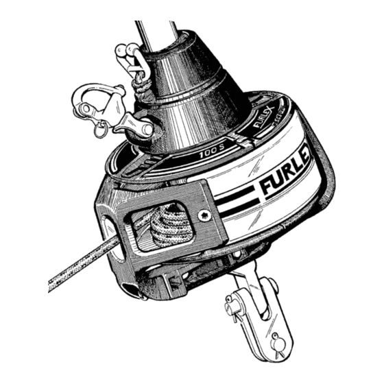
This permits smoother furling and considerably reduces bearing wear. Furlex 100 S for Ø 6 mm forestay can be supplied with an optional external rigging screw. … The Furlex luff section has the same dimensions over its whole length. The entire luff is furled …... - Page 5 1. Forestay /eye terminal 11. Tack ring 2. Top guard 12. Adapter 3. Halyard swivel 13. Fork / fork toggle 4. Snap shackle 14. Line drum flange halves 5. Luff extrusion 15. Line guard housing 6. Distance tube 16. Line guard 7.
-
Page 6: Assembly
ASSEMBLY 2 Checklist 2.1 Furlex box Forestay wire Halyard Swivel (with snap shackle) Lower bearing assembly with snap shackle 4 Line drum flange halves Line guard housing Line guide fitting... - Page 7 Furling line 2 halyard leads 508-135 with insulator sheets incl. 4 screws Drill bit Ø 5.3 mm (7/32”) Torx bit set (T15/20/25/30/40/45) 4 stanchion blocks Prefeeder incl. shock cord and hook Locking adhesive Lubricating grease Top guard incl. 2 screws Instructions Spare parts list Certificate of guarantee...
-
Page 8: Foil Pack
2.2 Foil pack: One x 1000 mm (39 3/8”) luff extrusion with long joint sleeve. One x 2000 mm (78 3/4”) luff extrusion with distance tube. 2400 mm (94 1/2”) luff extrusions with distance tube + joint sleeves. (Number dependent on length ordered). Sail feeder (sail feeder + sailfeeder connector.) One long connecting spring for each... -
Page 9: Assembly Preparations
3 Assembly preparations 3.1 Forestay attachment - guiding principle The guiding principle is that the forestay connections should allow sufficient articulation in all directions. In most cases a toggle should be fitted between the Furlex stay and the forestay attachment. 3.2 Mast attachment Some Seldén forestay attachment options are shown below, illustrating the rules and exceptions. -
Page 10: Dimension Of Lower Bearing Assembly
3.3.1 Dimensions of lower bearing assembly (mm) 3.3.2 Dimensions of top eye terminal Fig. 3.3.a Fig. 3.3.b Wire dim. Ø 4 (5/32”) ~ 100 (4 ”) ø 8.2 (5/16”) 4 (5/32”) Ø 5 (3/16”) Ø 152 (6”) ~ 100 (4 ”) 80 (3 1/8”) Ø... -
Page 11: Table Of Measurements For Toggles
3.3.3 Table of measurements for toggles (Toggles available from your Furlex dealer) Forestay Dimensions Toggle type Ø 4 (5/32”) Ø 5 (3/16”) Ø 6 (1/4”) Eye / fork toggle Article no. 174-102 174-103 174-104 Length (H) 25 (1”) 35 (1 3/8”) 40 (1 1/2”) Ø... -
Page 12: Assembly Below Deck
3.4 Assembly below deck The lower bearing assembly can be fitted below deck inside an anchor well. The advantage is that the sail’s luff length is maximized and the access around the forestay is improved. The disadvantage is a more complicated route for the furling line, increasing furling resistance. The diagrams below illustrate various methods of installation. -
Page 13: Calculating The Length Of The Forestay Wire
Furlex fitted above deck, but with the forestay fitting in the anchor well. Use the Furlex extension toggle. For a larger gap, use a custom-made stainless steel bar or rod stay. For Ø 6 only, the Furlex rigging screw or extension link may also be used. -
Page 14: Calculating The Length Of The Luff Extrusion
3.6 Calculating the length of the luff extrusion 1. Insert the length of the new forestay wire (WL) as calculated in table 1 into table 2, in the row marked WL. 2. Calculate the number of full length extrusions and the length of the top extrusion. Your Example 3.6.1... - Page 15 Fig. 3.5.a...
-
Page 16: Assembly Of The Furlex-System
4 Assembly of the Furlex System 4.1 Assembly of the luff section Assembly should be carried out on a horizontal surface. Connect the luff extrusions one by one, starting at the lower bearing assembly. Fig. 4.1.a Fit the short connecting spring (L=103 mm/4 1/8”) to the 1000 mm (39 3/8”) extrusion. The larger hook must be on the free end. -
Page 17: Fitting The Wire Terminal
Fig. 4.1.e Fit the halyard swivel over the top end of the extrusion, slide it down as far as the sail feeder gap and secure it in this position with adhesive tape. Fit the top guard and secure it with the two pre- fitted screws. - Page 18 Fig. 4.2.d The core of the wire should protrude approx. 2 mm (3/32”) from the wedge. Space the outer strands of the wire evenly around the wedge and push it into the socket so that the strands are held in place. Tap the wire lightly so the outerstrands jam in the seat. NOTE! Check that no strands slip into the slot of the wedge.
- Page 19 15:2 Fig. 4.2.h Fig. 4.2.i Furlex 100 S with Ø 4 or Ø 5 mm wire: Furlex 100 S with Ø 6 mm wire: The swaged end fitting will protrude completely. About half of the swaged fitting will be exposed.
-
Page 20: Fitting The Line Drum And Line Guide
Installing the sail feeder: Fig. 4.2.n Press on the sail feeder connector from the front of the luff extrusion. Fig. 4.2.o Clip the sail feeder into the connector’s top recess, then press the sail feeder’s lower edge until it snaps into place. We recommend fitting the Furlex system onto the boat at this stage. - Page 21 Remove the screw A in the lineguard bracket. Slide the bracket over the narrowest part B of the eye wire terminal. Then slide the bracket Fig. 4.3.d upwards. Replace the screw A and tighen it lightly. Fit the lower halves. Fig.
-
Page 22: Halyard Routing
5 Halyard routing The angle between the halyard and the forestay must be 5 - 10° - see fig. 5.4.c. If this angle is less, the halyard may wrap around the luff section when the sail is being furled, possibly damaging the halyard and the luff extrusion. -
Page 23: Halyard Sheave Box
5.2 Halyard sheave box A sheave box can also be fitted to the mast to meet the 5-10° requirement. The sheave box will not damage the halyard, nor is it worn by the wire. Installation is more complicated but the box will eliminate the need to replace the halyard leads in future as above. - Page 24 For the halyard routing to work properly, the halyard swivel must be in the correct position to achieve the required angle of 5 - 10°. If the sail does not have the required luff length, this needs to be adjusted . (See Sail, 7.1) 10°...
-
Page 25: Furling Line Arrangement
6 Furling line arrangement 6.1 Functional description As the sail unfurls, the furling line is wound onto the line drum. It is centred on the line drum through the hole in the line guide fitting, which has a stainless steel bush to reduce friction and wear on the line. -
Page 26: Routing Of The Furling Line
6.3 Routing of the furling line The line should be led aft to the cockpit via the lead blocks included in the Furlex package. The lead blocks are mounted on stanchions and the pulpit. See fig. 6.4.a-6.4.f. Fig. 6.3.b Fig. 6.3.a Slacken the locking screw ... -
Page 27: Fitting The Stanchion Blocks
6.4 Fitting the stanchion blocks The Furlex kit contains 4 stanchion blocks to be fitted to a 25 mm (1”) stanchion or pulpit. The block has a ball-and-socket joint and can be angled in any direction. Fig. 6.4.a Fig. 6.4.b Insert the clamp halves into the sheave house as Squeeze the clamps together around the shown. -
Page 28: The Sail
7 The Sail 7.1 Adapting the sail to the Furlex system To fit the Furlex system , an existing sail may need a number of modifications. The maximum luff … length is calculated as shown in Table 7.1.1 and fig. 7.1.b. FL (F+E) (existing forestay length as per Table 3.5.1 - less head and tack deduction). -
Page 29: Table Of Sail Measurements
7.1.1 Table of sail measurements 100 S Forestay dimension Ø 4 & 5 Ø 6 Head deduction F 360 (14”) 375 (14 3/4”) Tack deduction E 280 (11”) 295 (11 5/8”) (Any additional toggle or link must be added to E) Cutback CB 60 (2 3/8”) Ø... -
Page 30: Determining The Length Of The Pendant
Smaller foresails such a cruising (working) jib will have a higher clew, giving better visibility under the sail, easier passage over the guard rail and less exposure to waves breaking over the foredeck in heavy weather. This type of sail often requires less adjustment of the sheeting position when reefed (See chap. -
Page 31: Operation
OPERATING MANUAL To derive the maximum benefit and enjoyment from your Furlex system, we recommend that you study this operating manual carefully. All safety-related information is indicated by the following symbol. Furlex is specified and manufactured using Metric dimensions. To assist owners unfamiliar with this system, the approximate equivalent Imperial dimension are given in brackets . -
Page 32: Halyard Routing
10 Halyard Routing 10.1 Summary IMPORTANT POINTS! Routing the halyard is one of the most important aspects of system assembly for safe, trouble- free … sailing using the jib furling and reefing system. The angle between the halyard and the forestay must be 5 - 10°. See fig. 5.4.b. If the angle is less, …... -
Page 33: Halyard Sheave Box
10.2 Halyard sheave box A sheave box can also be fitted to the mast to meet the 5–10° requirement. A sheave box will not damage the halyard nor is it worn by it either. Installation is more complicated but the box will eliminate the need to replace halyard leads in the future, as mentioned above. -
Page 34: Sailing With Furlex
11 Sailing with Furlex 11.1 To hoist the sail The forestay must be properly tensioned each time the sail is hoisted. You should therefore tension the backstay and any running backstays before hoisting the sail. Tension the forestay for hard close-reach sailing before the sail is hoisted. If the sail is hoisted firmly tensioned before the forestay, this may put excess strain on the halyard, halyard swivel and sail when the forestay is tensioned afterwards. -
Page 35: Unfurling The Sail
If the furling line exits on the port side of the line drum, the sail should be hoisted in the starboard groove. If the line exits on the starboard side, use the port groove. Hoisting the sail in the ”right” groove reduces initial resistance when furling the sail, which then has less of a ”fold”... -
Page 36: Furling The Sail
11.3 Furling the sail 1. Release the windward sheet and ensure that it can run freely. 2. Furl the sail by pulling the furling line. Release the leeward sheet but keep a little tension on it, for example by placing a turn around a winch. It is important to furl the sail tightly and evenly, as a sail which is furled too loosely can blow out a little in strong winds. -
Page 37: Reefing
12 Reefing The size of the working sail area is infinitely variable with a jib furling and reefing system. Even if the sail is designed as a furling sail incorporating foam etc. and the Furlex system is equipped with a ”free turn”... -
Page 38: Setting A Reefed Sail From The Furled Position
12.3 Setting a reefed sail from the furled position You will achieve the best sail shape by first unfurling the sail completely and then reefing down … to the appropriate size. Pull in the furling line and keep the sheet well tensioned. The sail will then form a tight roll and its shape will be improved. -
Page 39: Furlex For Racing
13 Furlex for racing Many racing yachtsmen have exploited the advantages of the jib furling and reefing system … with reat success. The sail can be partly furled before the start, giving good visibility and easy manoeuvring of the boat. Just before starting, the sail is unfurled and the boat crosses the line under full sail. -
Page 40: Adjusting The Forestay Length
14 Adjusting the forestay length The Furlex 100 S for Ø 6 mm forestay may be supplied with or without an external rigging screw. For Ø 4 and Ø 5 mm forestay, there are no Furlex- rigging screw available. 14.1 Furlex with rigging screw On a system with a rigging screw, the forestay length can be adjusted. -
Page 41: Furlex Without Rigging Screw
Dismantling, chap. 17 and Assembly of the Furlex System, chap. 4. NOTE! Never shorten the system by removing the lower Furlex toggle. (See Deck attachments, chap. 3.3). A Furlex 100 S with Ø 6 mm forestay can be retrofitted with a rigging screw. Contact your Furlex dealer. -
Page 42: Lubricating The Lower Bearing Assembly
15 Maintenance of the Furlex System To ensure that the system rotates easily and functions satisfactorily year after year, regular maintenance should be carried out. This should be done once a year, or perhaps when the boat is unrigged at the end of each season. -
Page 43: Cleaning The Furlex
15.3 Cleaning the Furlex Wash and rinse the entire Furlex system with fresh water and a mild detergent to remove dirt and salt crystals. Note! Some detergents contain substances which can cause aluminium to corrode, so it is important to rinse all detergent off thoroughly. -
Page 44: Rigging
16 Rigging The Furlex system is best transported and rigged together with the mast. 16.1 Fitting the Furlex on a stepped mast 1. Slacken the backstay as much as possible, but make sure that any rigging screw is not unscrewed so far that the threads are no longer visible ”on the inside”. -
Page 45: Stepping The Mast With Furlex Fitted
16.2 Stepping the mast with Furlex fitted 1. Lay the mast with the front uppermost. 2. Connect the top end of the Furlex system to the forestay attachment. 3. Lift the mast with the Furlex system lying on the leading edge of the mast. 4. -
Page 46: Dismantling
17 Dismantling NOTE! Do not dismantle the halyard swivel or lower bearing assembly. You will find it difficult to re-assemble them correctly (the ball-bearings are loose and difficult to refit!) . Contact your Furlex dealer if service is required. 17.1 Halyard swivel The halyard swivel can be removed from the system by removing the top guard and sliding it over the end of the forestay wire. -
Page 47: Lineguide / Line Drum
17.3 Lineguide / Line drum 1. Unwind all the line from the line drum. Note the number of turns of line (for reassembly). Fig. 17.3.b Fig. 17.3.a Remove the line guide fitting. Loosen screws screw . Fig. 17.3.c Press the clip hook at the flange halves and pull. Fig. -
Page 48: Forestay
1 7 . 4 F o r e s t a y To shorten the wire or to remove it. For a better understanding of the following instructions, we recommend that you first read the section on assembly on chap. 4.1. Remove the toggles from the wire terminal. -
Page 49: Lower Bearing Assembly
1 7 . 5 L o w e r b e a r i n g a s s e m b l y Remove the sailfeeder. See Sailfeeder, chap. 17.2. Remove the hook which holds the pre-feeder shock cord to the sailfeeder gap. Pull out the pre-feeder. -
Page 50: Troubleshooting
18 Trouble shooting Problem Probable cause Action 18.1 ”The sail will not unfurl or • The jib halyard is wrapped around the • Ease the halyard slightly and try to will only partly unfurl” luff extrusion. reverse the system. Refer to the ass- embly and operating manual chap. - Page 51 Problem Probable cause Action 18.5 ”The sail is hard to hoist” • The luff tape is too thick. • Return the sail to the sailmaker and refer to Furlex manual, chap. 7.1.1 Table of sail measurements. • The sail is caught on something or •...
-
Page 52: Checklist
19 Checklist Go through the checklist below and make sure that all the important instructions have been carried out. This will ensure that the Furlex system functions safely and reliably under all conditions. 19.1 Points to check before sailing chapter Check that the angle between the halyard and forestay is 5 - 10°...
Need help?
Do you have a question about the Furlex 100 S and is the answer not in the manual?
Questions and answers
What size bead goes in channel