Table of Contents
Advertisement
Advertisement
Table of Contents

Related Manuals for Selden Furlex 200 S


Summary of Contents for Selden Furlex 200 S
- Page 1 595-104-E 2011-02-01 200 S & 300 S Manual Furlex 200 S & 300 S...
-
Page 2: Introduction
1 Introduction 1.1 The manual To derive the maximum benefit and enjoyment from your Furlex-system, we recommend that you study this manual carefully. The manual is divided into two sections, one dealing with ASSEMBLY and one with OPERATION. Each section contains references to the other. It is very important to read and note these cross references. -
Page 3: Table Of Contents
Contents Page Page OPERATING MANUAL 1 Introduction 10 Halyard routing The manual 10.1 Summary Product information 10.2 Halyard sheave box ASSEMBLY 10.3 Spinnaker halyard 2 Checklist Furlex box 11 Sailing with Furlex Foil pack 11.1 To hoist the sail Tools 11.2 Unfurling the sail 3 Assembly preparations... -
Page 4: Product Information
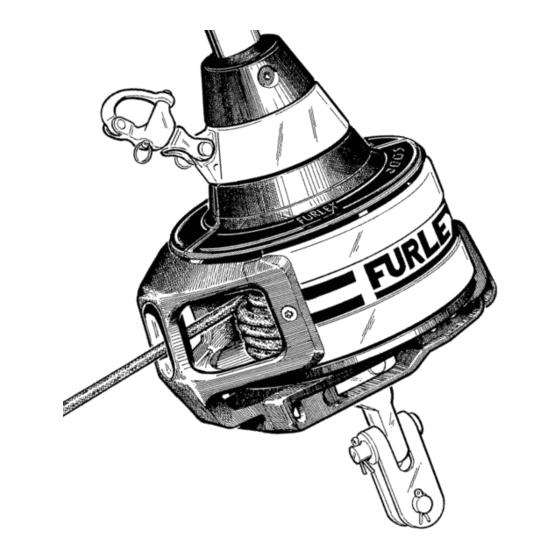
1.2 Product information When the original Furlex was introduced in 1983, it was not a pioneering project. The design included features which improved on other manufacturers’ products to increase performance, function and reliability. The first systems sold are still functioning well, providing ample proof of the design’s effectiveness and long-term staying power. - Page 5 1. Forestay /eye terminal 12. Tack ring 2. Top guard 13. Adapter 3. Halyard swivel 14. Terminal part or rigging screw 4. Snap shackle 15. Fork / fork toggle 5. Luff extrusion 16. Line drum half 6. Distance tube 17. Line guard housing 7.
-
Page 6: Assembly
ASSEMBLY 2 Checklist 2.1 Furlex box Forestay wire with top bearing Wire terminal with distance bearing or with rigging screw function. (Depends on which type ordered.) Halyard swivel with snap shackle Lower bearing assembly with snap shackle Two line drum halves (one with furling line end lock) Line guide fitting... - Page 7 Line guard housing Line guide locking block Furling line 200 S: 2 halyard leads 508-159 with insulator sheets incl. 4 screws Drill bit Ø 5,3 mm (7/32”) 300 S: 2 halyard leads 508-128 with insulator sheets incl. 6 screws Drill bit Ø 5.3 mm (7/32”) Torxbits (T15/20/25/30/40/45) 200 S: 4 stanchion blocks 538-971-02...
-
Page 8: Foil Pack
2.2 Foil pack One 1000 mm (39 3/8”) luff extrusion with long joining sleeve. One 2000 mm (78 3/4”) luff extrusion with distance tube. 2400 mm (94 1/2”) luff extrusions with distance tube + joining sleeve (number dependent on length ordered.) Sail feeder (sail feeder + sailfeeder connector.) One short connecting plate for each... -
Page 9: Assembly Preparations
3 Assembly preparations 3.1 Forestay attachment - guiding principle The guiding principle is that the forestay connections should allow sufficient articulation in all directions. In most cases a toggle should be fitted between the Furlex stay and the forestay attachments. 3.2 Mast attachment Some Seldén forestay attachment options are shown below, illustrating the rules and exceptions. -
Page 10: Dimensions Of Lower Bearing Assembly
3.3.1 Dimensions of lower bearing assembly (mm) 3.3.2 Dimensions of top eye terminal Fig. 3.3.a Fig. 3.3.b Furlex Series ‑DW Wire Dim. ø 6 (1/4”) 12,2 (1/2”) 6 (1/4”) 200 S Ø 186 (7 1/3”) 120 (4 3/4”) 95 (3 3/4”) ø... -
Page 11: Table Of Measurements For Toggles
3.3.3 Table of measurements for toggles (Toggles available from your Furlex dealer) Forestay Dimensions Toggle type Ø 6 (1/4”) Ø 7 (9/32”) Ø 8 (5/16”) Ø 10 (3/8”) Eye / fork toggle Article no. 174-104 174-105 174-106 174-107 Length 40 (1 1/2”) 45 (1 3/4”) 50 (2”) 65 (2 1/2”) -
Page 12: Assembly Below Deck
3.4 Assembly below deck The lower bearing assembly can be fitted below deck inside an anchor well. The advantage is that the sail’s luff length is maximized and the access around the forestay is improved. The disadvantage is a more complicated route for the furling line, increasing furling resistance. The diagrams below illustrate various methods of installation. -
Page 13: Calculating The Length Of The Forestay Wire
Furlex fitted above deck, but with the forestay fitting in the anchor well. Use the Furlex extension toggle. For a larger gap, use a custommade stainless steel bar or rod stay. Short wire pennants are not recommended as forestay forces may not be distributed evenly, and wire will not resist the Fig. -
Page 14: Calculating The Length Of The Luff Extrusion
3.6 Calculating the length of the luff extrusion 1. Insert the length of the new forestay wire (WL) as calculated in ”Table 1” into ”Table 2”, in the row marked WL. 2. Calculate the number of full length extrusions and the length of the top extrusion. Example Your 3.6.1... - Page 15 Fig. 3.5.a...
-
Page 16: Assembly Of The Furlex-System
4 Assembly of the Furlex-system 4.1 Assembly of the luff section Assembly should be carried out on a horizontal surface. Connect the luff extrusions one by one as follows: Fig. 4.1.a The long joining sleeve must be in the 1000 mm (39 3/8”) luff extrusion when commencing assembly. - Page 17 Fig. 4.1.e Fit a joining sleeve into the next 2400 mm (94 1/2”) extrusion together with a connecting plate. Connect this to the lower extrusions. Using a spare joining sleeve, push in the distance tube from the top until the lower joining sleeve touches the distance tube below the join. Check that the distance (J) between the end of the distance tube and the end of the extrusion is approximately half the length of a joining sleeve.
-
Page 18: Fitting The Wire Terminal (Or Rigging Screw)
4.2 Fitting the wire terminal (or rigging screw) Stretch the Furlex wire out by hand on a flat surface. Be careful when you open the wire coil as it may uncoil quickly. Note: Be careful when you open the wire coil! 2. - Page 19 Fig. 4.2.c Slide the wedge over the core (7 strands) of the wire. The core of the wire should protrude approx. 2 mm (3/32”) from the wedge. Space the outer strands of the wire evenly around the wedge and bring down the socket so that the strands are held in place. Hold an adjustable spanner between the 1000 mm extrusion and the socket.
- Page 20 16. Check the length FL of the stay acc. ”Table 1” (3.5.1) & Fig. 3.5.a. If the Furlex rigging screw is fitted, it should be 50% extended. (”Rigging screw adjustment”, see table 14.1.1.) 17.1 17.2 Fig. 4.2.g Fig. 4.2.l Terminal part: Rigging screw: Press the spacer bush over the wire.
-
Page 21: Fitting The Line Drum And Line Guide
4.3 Fitting the line drum and line guide The line drum consists of two halves. These are easier to fit after the Furlex is fitted to the boat. Feed the furling line through the hole in the line guide fitting and then through the hole in the Fig. - Page 22 6. Tighten the screw lightly. Fig. 4.3.f Adjust the line guide vertically so that it is midway between the line drum flanges. If the casing or line guard come into contact with the line drum flanges, unnecessary friction will be Fig.
-
Page 23: Halyard Routing
5 Halyard routing The angle between the halyard and the forestay must be 5–10° - see Fig. 5.4.c. If this angle is less, the halyard may wrap around the luff section when the sail is being furled, possibly damaging the halyard and the luff extrusion. -
Page 24: Halyard Sheave Box
5.2 Halyard sheave box A sheave box can also be fitted to the mast to meet the 5–10° requirement. The sheave box will not damage the halyard, nor is it worn by the wire. Installation is more complicated but the box will eliminate the need to replace the halyard leads in future as above. - Page 25 For the halyard routing to work properly, the halyard swivel must be in the correct position to achieve the required angle of 5–10°. If the sail does not have the required luff length, this needs to be adjusted. (See Sail, 7.1.) 0–5°...
-
Page 26: Furling Line Arrangement
6 Furling line arrangement 6.1 Functional description As the sail unfurls, the furling line is wound onto the line drum. It is centred on the line drum through the hole in the line guide fitting, which has a stainless steel bush to reduce friction and wear on the line. -
Page 27: Routing Of The Furling Line
6.3 Routing of the furling line The line should be led aft to the cockpit via the lead blocks included in the Furlex package. The lead blocks are mounted on stanchions and the pulpit. See Fig. 6.4.a–6.4.f for how to fit the 200 Series and Fig. -
Page 28: Fitting The Stanchion Blocks
6.4 200 S: Fitting the stanchion blocks The Furlex kit contains 4 stanchion blocks to be fitted to a 25 mm (1”) stanchion or pulpit. The block has a ball-and-socket joint and can be angled in any direction. Fig. 6.4.a Fig. -
Page 29: The Sail
7 The Sail 7.1 Adapting the sail to the Furlex-system To fit the Furlex-system , an existing sail may need a number of modifications. The maximum luff length is calculated as shown in Table 7.1.1 and Fig. 7.1.b. FL -(F+E) (existing forestay length as per Table 3.5.1 –... -
Page 30: Table Of Sail Measurements
7.1.1 Table of sail measurements 200 S 300 S Furlex type Head deduction F 540 (21 1/2”) 550 (22”) Tack deduction E 330 (13”) 400 (15 3/4”) (Any additional toggle or link must be added to E) Cutback CB 60 (2 3/8”) 80 (3 1/8”) Internal diameter of luff groove DLG Ø... -
Page 31: Determining The Length Of The Pendant
Smaller foresails such a cruising (working) jib will have a higher clew, giving better visibility under the sail, easier passage over the guard rail and less exposure to waves breaking over the foredeck in heavy weather. This type of sail often requires less adjustment of the sheeting position when reefed (See Chapter 12, ”Reefing”). -
Page 32: Operating Manual
OPERATING MANUAL To derive the maximum benefit and enjoyment from your Furlex-system, we recommend that you study this operating manual carefully. All safety-related information is indicated by the following symbol. Furlex is specified and manufactured using Metric dimensions. To assist owners unfamiliar with this system, the approximate equivalent Imperial dimension are given in brackets. -
Page 33: Halyard Routing
10 Halyard Routing 10.1 Summary IMPORTANT POINTS! Routing the halyard is one of the most important aspects of system assembly for safe, trouble- free sailing using the jib furling and reefing system. The angle between the halyard and the forestay must be 5–10°. See Fig. 5.4.b. If the angle is less, the halyard may wrap around the luff section when the sail is being furled, possibly damaging the halyard and the luff extrusion. -
Page 34: Halyard Sheave Box
10.2 Halyard sheave box A sheave box can also be fitted to the mast to meet the 5–10° requirement. The sheave box will not damage the halyard, nor is it worn by the wire. Installation is more complicated but the box will eliminate the need to replace the halyard leads in future as above. -
Page 35: Sailing With Furlex
11 Sailing with Furlex 11.1 To hoist the sail The forestay must be properly tensioned each time the sail is hoisted. You should therefore tension the backstay and any running backstays before hoisting the sail. Tension the forestay for hard close-reach sailing before the sail is hoisted. If the sail should be hoisted and firmly tensioned before the forestay, this may put excess strain on the halyard, halyard swivel and sail when the forestay is tensioned afterwards. -
Page 36: Unfurling The Sail
Hoisting the sail in the correct groove through the sail feeder. If the furling line exits on the port side of the line drum, the sail should be hoisted in the starboard groove. If the line exits on the star- board side, use the port groove. -
Page 37: Furling The Sail
3. Place a turn of the leeward genoa sheet around a winch and unfurl the sail by pulling in the sheet. Once the wind catches the sail it will unfurl more easily. The best point of sail for unfurling is between close reach and beam reach, as the wind will then fill the sail quickly. -
Page 38: Reefing
12 Reefing The size of the working sail area is infinitely variable with a jib furling and reefing system. Even if the sail is designed as a furling sail incorporating foam etc. and the Furlex-system is equipped with a ”free turn”... -
Page 39: Setting A Reefed Sail From The Furled Position
12.3 Setting a reefed sail from the furled position You will achieve the best sail shape by first unfurling the sail completely and then reefing down to the appropriate size. Pull in the furling line and keep the sheet well tensioned. The sail will then form a tight roll and its shape will be improved. -
Page 40: Furlex For Racing
13 Furlex for racing Many racing yachtsmen have exploited the advantages of the jib furling and reefing system with great success. The sail can be partly furled before the start, giving good visibility and easy manoeuvring of the boat. Just before starting, the sail is unfurled and the boat crosses the line under full sail. If the boat has a small crew, the advantages are obvious. -
Page 41: Adjusting The Forestay Length
14 Adjusting the forestay length The Furlex 200 S and 300 S may be supplied with or without an integral rigging screw. 14.1 Furlex with rigging screw On a system with an integral rigging screw, the forestay length can be adjusted. This is the primary task of the rigging screw. -
Page 42: Rigging Screw Adjustment
6. Place one wrench over the flat faces of the wire terminal and the other over the flat faces of the rigging screw body. Adjust the position of the rigging screw by turning the body of the rigging screw until the desired forestay length is obtained. Note! Do not turn the wire terminal. The rigging screw has a stop at the maximum position to which it can be unscrewed. -
Page 43: Maintenance Of The Furlex-System
15 Maintenance of the Furlex-system To ensure that the system rotates easily and functions satisfactorily year after year, regular maintenance should be carried out. This should be done once a year, or perhaps when the boat is unrigged at the end of each season. -
Page 44: Cleaning The Furlex
15.3 Cleaning the Furlex Wash and rinse the entire Furlex-system with fresh water and a mild detergent to remove dirt and salt crystals. Note! Some detergents contain substances which can cause aluminium to corrode, so it is important to rinse all detergent off thoroughly. When the parts have dried, the anodized surfaces of the luff extrusions can be treated with a silicon- free boat polish or wax. -
Page 45: Rigging
16 Rigging The Furlex-system is best transported and rigged together with the mast. 16.1 Fitting the Furlex on a stepped mast 1. Slacken the backstay as much as possible, but make sure that any rigging screw is not unscrewed so far that the threads are no longer visible ”on the inside”. 2. -
Page 46: Stepping The Mast With Furlex Fitted
16.2 Stepping the mast with Furlex fitted 1. Lay the mast with the front uppermost. 2. Connect the top end of the Furlex-system to the forestay attachment. 3. Lift the mast with the Furlex-system lying on the leading edge of the mast. 4. -
Page 47: Lineguide
Re-installing the sail feeder: Fig. 17.2.d Fig. 17.2.e Push on the connector from the front of the luff Hook on the sailfeeder at its upper edge. Secure section. with tape. Fit the screws. 17.3 Lineguide 1. Unwind all the line from the line drum. Note the number of turns of line (for reassembly). Fig. -
Page 48: Line Drum
17.4 Line drum 1. Dismantle the line drum halves. One turn of the furling line wound around the line drum during disassembly prevents the free half of the drum from falling overboard. Fig. 17.4.a Insert a screwdriver under one of the connecting clips. At Fig. -
Page 49: Wire Terminal
17.6 Wire terminal Remove the spacer bush. This has a longitudinal slot to allow the wire to be removed. (Only applies to Furlex without rigging screw.) Remove the terminal part (or rigging screw) from the socket. See fig. 17.5.b & fig. 4.2.a. Remove the former from the bottom of the eye part. -
Page 50: Trouble Shooting
If, due to contamination or damage this method fails the connection parts protruding boss’ can be drilled out. Use a Ø 6 mm drill bit for 200 S, Ø 8 mm for 300 S. Reassembly of the luff extrusion. Check all metal corners, edges and holes for damage, and file down if necessary. Clean the wire and all extrusion parts with fresh water. - Page 51 Problem Probable cause Action • The furling line has become tangled • Unfurl the sail and take it down. on the drum. Rewind the furling line. Unfurl with slight drag on the furling line in future and avoid having too much line on the drum.
-
Page 52: Checklist
19 Checklist Go through the checklist below and make sure that all the important instructions have been carried out. This will ensure that the Furlex-system functions safely and reliably under all conditions. 19.1 Points to check before sailing Chapter Check that the angle between the halyard and forestay is 5–10° when the sail is hoisted.
Need help?
Do you have a question about the Furlex 200 S and is the answer not in the manual?
Questions and answers