Table of Contents
Advertisement
This is a safety alert symbol and should never be ignored. When you see this symbol on labels or in
manuals, be alert to the potential for personal injury or death.
As with any mechanical equipment, personal injury can
result from contact with sharp sheet metal edges. Be
careful when you handle this equipment.
Unit Dimensions ................................................................ 2
Parts Arrangement............................................................. 3
Gas Furnace ...................................................................... 4
Shipping and Packing List ................................................. 4
Safety Information ............................................................. 4
Use of Furnace as a Construction Heater ......................... 5
General .............................................................................. 6
Combustion, Dilution & Ventilation Air ............................... 6
Setting Equipment ............................................................. 9
Filters ............................................................................... 13
Duct System .................................................................... 13
Pipe & Fittings Specifications .......................................... 13
Joint Cementing Procedure ............................................. 15
Venting Practices ............................................................. 16
*P507404-04*
(P) 507404-04
507404-04
INSTALLATION INSTRUCTIONS
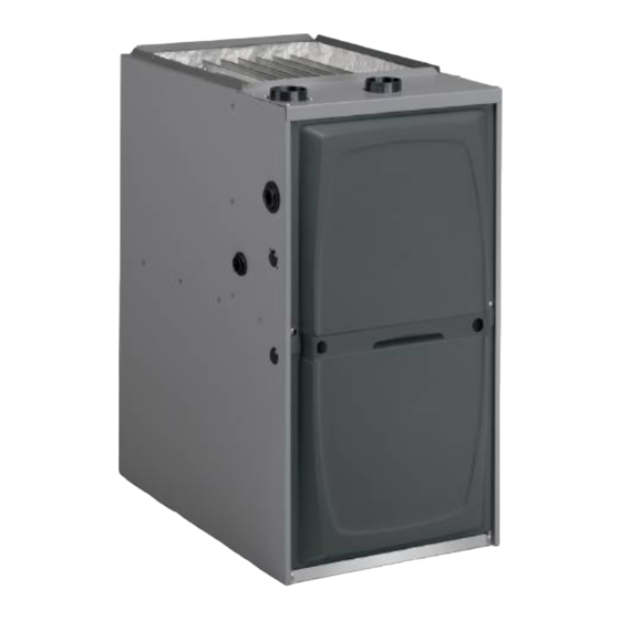
A96US2V
Warm Air Gas Furnace
Upflow/Horizontal Left Air Discharge
Direct Vent & Non-Direct Vent
This manual must be left with the homeowner for future reference.
CAUTION
TABLE OF CONTENTS
Improper installation, adjustment, alteration, service
or maintenance can cause property damage, personal
injury or loss of life. Installation and service must
be performed by a licensed professional installer (or
equivalent), service agency or the gas supplier.
Vent Piping Guidelines .................................................... 17
Gas Piping ....................................................................... 39
Electrical .......................................................................... 42
Blower Motor Performance .............................................. 52
Unit Start-Up .................................................................... 62
Gas Pressure Adjustment ................................................ 64
High Altitude Information ................................................. 65
Other Unit Adjustments.................................................... 65
Integrated Control Diagnostic Modes .............................. 68
Service............................................................................. 74
Planned Service .............................................................. 76
Repair Parts List .............................................................. 77
Start-Up & Performance Check List ................................ 78
A Lennox International, Inc. Company
Issue 1621
WARNING
Manufactured By
Allied Air Enterprises LLC
215 Metropolitan Drive
West Columbia, SC 29170
Page 1 of 80
Advertisement
Table of Contents

Related Manuals for Allied Air A96US2V

Summary of Contents for Allied Air A96US2V
-
Page 1: Table Of Contents
Repair Parts List .............. 77 Joint Cementing Procedure ..........15 Start-Up & Performance Check List ........ 78 Venting Practices ............. 16 Manufactured By Allied Air Enterprises LLC *P507404-04* A Lennox International, Inc. Company 215 Metropolitan Drive West Columbia, SC 29170... -
Page 2: Unit Dimensions
A96UH2V Unit Dimensions - inches (mm) 1 NOTE - 20 C/D (5 Ton) size units installed in upflow applications that require air volumes of 1800 cfm (850 L/s) or greater must have one of the following: 1. Single side return air with transition, to accommodate 20 x 25 x 1 in. -
Page 3: Parts Arrangement
EXPANDED VIEW Figure 1 507404-04 Issue 1621 Page 3 of 80... -
Page 4: Gas Furnace
A96US2V Gas Furnace Shipping and Packing List The A96UH2V Category IV gas furnace is shipped ready for 1 - Assembled Gas Furnace installation in the upflow or horizontal position. The furnace 1 - Bag assembly containing the following: is shipped with the bottom panel in place. The bottom panel... -
Page 5: Use Of Furnace As A Construction Heater
In Canada, installation must conform with current National In Canada, all electrical wiring and grounding for the unit Standard of Canada CSA-B149 Natural Gas and Propane must be installed according to the current regulations of Installation Codes, local plumbing or waste water codes and the Canadian Electrical Code Part I (CSA Standard C22.1) other applicable local codes. -
Page 6: General
• The input rate and temperature rise must be set per the furnace rating plate. WARNING • One hundred percent (100%) outdoor air must be provided for combustion air requirements during construction. The State of California has determined that this product Temporary ducting may supply outdoor air to the furnace. - Page 7 air is brought into the house for combustion, negative infiltration. If the furnace is located in a building of tight pressure (outside pressure is greater than inside pressure) construction with weather stripping and caulking around will build to the point that a down draft can occur in the the windows and doors, follow the procedures in the “Air furnace vent pipe or chimney.
- Page 8 Air from Outside Equipment in Confined Space - All Air from Outside If air from outside is brought in for combustion and ventilation, the confined space shall be provided with two permanent openings. One opening shall be within 12” (305 mm) of the top of the enclosure and one within 12”...
-
Page 9: Setting Equipment
INSTALLATION When ducts are used, they shall be of the same cross- sectional area as the free area of the openings to which they Setting Equipment connect. The minimum dimension of rectangular air ducts shall be no less than 3 inches (75 mm). In calculating free WARNING area, the blocking effect of louvers, grilles, or screens must be considered. - Page 10 Return Air Guidlines WARNING Return air can be brought in through the bottom or either side of the furnace installed in an upflow application. If the Improper installation of the furnace can result in furnace is installed on a platform with bottom return, make personal injury or death.
- Page 11 Optional Return Air Base (Upflow Applications Only) SIDE VIEW FRONT VIEW NOTE: Optional side return air filter kits are not for use with return air base. 1 Both the unit return air opening and the base return air opening must be covered by a single plenum or IAQ cabinet. Minimum unit side return air opening dimensions for units requiring 1800 cfm or more of air (W x H): 23 x 11 in.
- Page 12 Typical Horizontal Application Horizontal Application Installation Clearances Right-Hand Discharge Figure 18 NOTE: When the furnace is installed on a platform or with *Front the horizontal suspension kit in a crawl space, it must be Back elevated enough to avoid water damage, accommodate Ends drain trap and to allow the evaporator coil to drain.
-
Page 13: Filters
Duct System Use industry approved standards to size and install the supply and return air duct system. This will result in a quiet and low-static system that has uniform air distribution. NOTE: This furnace is not certified for operation in heating mode (indoor blower operating at selected heating speed) with an external static pressure which exceeds 0.8 inches w.c. - Page 14 CAUTION IMPORTANT Solvent cements for plastic pipe are flammable liquids A95UH2V/95G2UHV exhaust and intake connections and should be kept away from all sources of ignition. are made of PVC. Use PVC primer and solvent cement Do not use excessive amounts of solvent cement when when using PVC vent pipe.
-
Page 15: Joint Cementing Procedure
Outdoor Termination Kits Usage A96DF2V Joint Cementing Procedure 1. Measure and cut vent pipe to desired length. All cementing of joints should be done according to the 2. Debur and chamfer end of pipe, removing any ridges specifications outlined in ASTM D 2855. or rough edges. -
Page 16: Venting Practices
Exhaust Piping 6. Promptly apply solvent cement to end of pipe and inside socket surface of fitting. Cement should be applied 1. In areas where piping penetrates joist or interior walls, lightly but uniformly to inside of socket. Take care to hole must be large enough to allow clearance on all keep excess cement out of socket. -
Page 17: Vent Piping Guidelines
In some applications which permit the use of several different sizes of vent pipe, a combination vent pipe may be used. Contact Allied Air Technical Service for assistance in sizing vent pipe in these applications. NOTE: The exhaust collar on all models is sized to accommodate 2”... -
Page 18: Horizontal Application
Use the following steps to correctly size vent pipe diameter. EXHAUST PIPE Horizontal Application NOTE: All horizontal runs of exhaust pipe must slope back toward unit. A minimum of 1/4” (6 mm) drop for each 12” (305 mm) of horizontal run is mandatory for drainage. - Page 19 Maximum Allowable Intake or Exhaust Vent Length in Feet Standard Termination at Elevation 0 - 4500 ft Number of 2" Pipe 2-1/2" Pipe 3" Pipe 90° Elbows Model Model Model Used 110 135 90 110 135 n/a 110 110 88 132 113 105 105 83 127 108...
- Page 20 Maximum Allowable Intake or Exhaust Vent Length in Feet Concentric Termination at Elevation 0 - 4500 ft Number of 2" Pipe 2-1/2" Pipe 3" Pipe 90° Elbows Model Model Model Used 110 135 110 135 100 100 n/a 116 116 109 109 100 111 111 104 104 106 106 99 101 101 94...
- Page 21 Maximum Allowable Exhaust Vent Lengths with Furnace Installed in a Closet or Basement Using Ventilated Attic or Crawl Space for Intake Air in Feet Standard Termination at Elevation 0 - 4500 ft Number 2" Pipe 2-1/2" Pipe 3" Pipe of 90° Model Model Model...
- Page 22 TYPICAL EXHAUST PIPE CONNECTIONS IN UPFLOW DIRECT OR NON-DIRECT VENT APPLICATIONS * When transitioning up in pipe size, use the shortest length of 2” PVC pipe possible. NOTE: Exhaust pipe and intake pipe must be the same diameter. Figure 23 TYPICAL EXHAUST PIPE CONNECTIONS IN HORIZONTAL DIRECT OR NON-DIRECT VENT APPLICATIONS (RIGHT HAND DISCHARGE SHOWN)
- Page 23 TYPICAL AIR INTAKE PIPE CONNECTIONS IN UPFLOW DIRECT VENT APPLICATIONS * When transitioning up in pipe size, use the shortest length of 2” PVC pipe possible. NOTE: Exhaust pipe and intake pipe must be the same diameter. Figure 25 TYPICAL AIR INTAKE PIPE CONNECTIONS IN HORIZONTAL DIRECT VENT APPLICATIONS (RIGHT HAND DISCHARGE SHOWN) * When transitioning up in pipe size, use the shortest length of 2”...
- Page 24 Follow the next two steps when installing the unit in Direct Typical Air Intake Pipe Connections Vent applications, where combustion air is taken from outdoors and flue gases are discharged outdoors. The Horizontal Non-Direct Vent Applications (Horizontal Right-Hand Air Discharge Application Shown) provided air intake screen must not be used in direct vent applications (outdoors).
- Page 25 Follow the next two steps when installing the unit in Non– Direct Vent applications where combustion air is taken from indoors and flue gases are discharged outdoors. Use field-provided materials and the factory-provided air intake screen to route the intake piping as shown in Figures 27 or 28.
- Page 26 Position termination according to location given in Figures 31 NOTE: During extremely cold temperatures, below and 32. In addition, position termination so it is free from any approximately 20° F (6.7° C), units with long runs of vent obstructions and 12” above the average snow accumulation. pipe through unconditioned space, even when insulated, may form ice in the exhaust termination that prevents the unit from operating properly.
-
Page 27: Vent Termination Clearances
VENT TERMINATION CLEARANCES FOR NON-DIRECT VENT INSTALLATIONS IN THE US AND CANADA INSIDE CORNER DETAIL Fixed Operable Fixed Closed Closed Operable AREA WHERE TERMINAL AIR SUPPLY INLET VENT TERMINAL IS NOT PERMITTED US Installations Canadian Installations Clearance above grade, veranda, 12 inches (305mm) or 12 in. - Page 28 VENT TERMINATION CLEARANCES FOR DIRECT VENT INSTALLATIONS IN THE US AND CANADA INSIDE CORNER DETAIL Fixed Operable Fixed Closed Closed Operable AREA WHERE TERMINAL AIR SUPPLY INLET VENT TERMINAL IS NOT PERMITTED US Installations Canadian Installations Clearance above grade, veranda, 12 inches (305mm) or 12 in.
- Page 29 Details of Intake and Exhaust Piping Terminations for Exiting Exhaust and Intake Vent Direct Vent Installations (no common pressure zone) NOTE: In Direct Vent installations, combustion air is taken from outdoors and flue gases are discharged to outdoors. NOTE: Flue gas may be slightly acidic and may adversely affect some building materials.
- Page 30 EXHAUST PIPE TERMINATION SIZE REDUCTION FIELD SUPPLIED WALL TERMINATION Termination MODEL Exhaust Pipe Size Pipe Size 045 and 070 1-1/2” (38 mm) 2” (51 mm), 2-1/2” (64 mm), 2” (51 mm) 3” (76 mm) 2” (51 mm) 3” (76 mm) 2”...
- Page 31 Figure 38 507404-04 Issue 1621 Page 31 of 80...
- Page 32 FLUSH-MOUNT SIDE WALL TERMINATION FIELD SUPPLIED WALL TERMINATION 51W11 Figure 40 Figure 39 Page 32 of 80 Issue 1621 507404-04...
- Page 33 DIRECT VENT CONCENTRIC ROOFTOP DIRECT VENT APPLICATION TERMINATION USING EXISTING CHIMNEY 71M80, 69M29 or 60L46 (US) 41W92 or 41W93 (Canada) NOTE: Do not discharge exhaust gases directly into any chimney or Figure 41 vent stack. If vertical discharge through an existing unused chimney or stack is required, insert piping inside chimney until the pipe open end is above top of chimney and terminates as illustrated.
- Page 34 Non-Direct Vent Roof Termination Kit Non-Direct Vent Field Supplied Wall (15F75 or 44J41) Termination Extended Figure 45 * Use wall support every 24” (610). Use two supports if extension is greater than 24” but less than 48”. Figure 47 Non-Direct Vent Field Supplied Wall Termination Non-Direct Vent Application Using Existing Chimney Figure 46...
- Page 35 Condensate Piping This unit is designed for either right or left side exit of CAUTION condensate piping in upflow applications. In horizontal applications, the condensate trap must extend below the Do not use copper tubing or existing copper condensate unit. An 8” service clearance is required for the condensate lines for drain line.
- Page 36 Condensate line must slope downward away from the trap to drain. If drain level is above condensate trap, condensate CAUTION pump must be used. Condensate drain line should be routed within the conditioned space to avoid freezing of condensate Do not use copper tubing or existing copper condensate and blockage of drain line.
- Page 37 Evaporator Coil using a Common Drain IMPORTANT When combining the furnace and evaporator coil drains together, the A/C condensate drain outlet must be vented to relieve pressure in order for the furnace pressure switch to operate properly. Condensate Trap with Optional Overflow Switch Figure 54 Figure 53 Evaporator Coil using a Common Drain...
- Page 38 TRAP / DRAIN ASSEMBLY USING 1/2” PVC or 3/4” PVC Figure 56 Page 38 of 80 Issue 1621 507404-04...
-
Page 39: Gas Piping
Gas Piping 6. In some localities, codes may require installation of a manual main shut-off valve and union (furnished by installer) external to the unit. Union must be of the CAUTION ground joint type. If a flexible gas connector is required or allowed by the IMPORTANT authority that has jurisdiction, black iron pipe shall be installed at the gas valve and extend outside the furnace... - Page 40 NOTE: BLACK IRON PIPE ONLY TO BE ROUTED INSIDE OF CABINET Figure 58 HORIZONTAL APPLICATIONS POSSIBLE GAS PIPING CONFIGURATIONS Figure 59 Page 40 of 80 Issue 1621 507404-04...
- Page 41 Table 9 507404-04 Issue 1621 Page 41 of 80...
-
Page 42: Electrical
Electrical The unit is equipped with a field makeup box. The makeup ELECTROSTATIC DISCHARGE (ESD) box may be moved to the right side of the furnace to facilitate Precautions and Procedures installation. Seal unused openings on left side with plugs removed from right side. - Page 43 Electrical Wiring 7. One line voltage “EAC” 1/4” spade terminal is provided on the furnace integrated control. Any electronic air cleaner or other accessory rated up to one amp can be connected to this terminal with the neutral leg of the WARNING circuit being connected to one of the provided neutral Risk of electrical shock.
- Page 44 Non-Communicating In non-communication applications this furnace is designed to operate in a SINGLE-STAGE mode or TWO-STAGE mode using a convention thermostat. For optimal performance in non-communicating applications, use a high quality electronic digital thermostat or any other with adjustable settings for 1st stage / 2nd stage ON/OFF differentials and adjustable stage timers.
- Page 45 507404-04 Issue 1621 Page 45 of 80...
- Page 46 ® Optional Accessories for use with any icomfort Touch System ® NOTE: Icomfort Wi-Fi THERMOSTAT SENSES HUMIDITY & CONTROLS HUM CONTACTS TO CYCLE HUMIDIFIER BASED 120V CONNECTIONS ON DEMAND. NO OTHER CONTROL OR HUMIDISTAT RE “HUM” CONTACT IS QUIRED. CLOSED ANYTIME OPTIONAL OUTDOOR AIR SENSOR FOR USE WITH HUMIDI...
- Page 47 Integrated Control Figure 56 507404-04 Issue 1621 Page 47 of 80...
- Page 48 Field Wiring Applications with Conventional Thermostat * Not required on all units. Table 13A Page 48 of 80 Issue 1621 507404-04...
- Page 49 Field Wiring Applications with Conventional Thermostat (continued) * Not required on all units. Table 13B 507404-04 Issue 1621 Page 49 of 80...
- Page 50 TABLE 11 Field Wiring Applications with Conventional Thermostat (continued) EL296 Field Wiring Applications With Conventional Thermostat (Continued) DIP Switch Settings and On-Board Links (figure 60) DIP Switch 1 Wiring Connections Thermostat On Board Links Must Be Cut To Select Thermostat Heating System Options Stages...
- Page 51 TABLE 11 Field Wiring Applications with Conventional Thermostat (continued) EL296 Field Wiring Applications With Conventional Thermostat (Continued) DIP Switch Settings and On-Board Links (figure 60) DIP Switch 1 Wiring Connections Thermostat On Board Links Must Be Cut To Select Thermostat Heating System Options Stages...
-
Page 52: Blower Motor Performance
A96US2V045B12S BLOWER PERFORMANCE (less filter) 0 through 0.8 in. w.c. (Heating) and 0 through 1.0 in. w.c. (Cooling) External Static Pressure Range HEATING Heating Speed Dip Switch Setting First Stage heating Speed - cfm Second Stage Heating Speed-cfm +24% 1115 +18% 1060 +12%... - Page 53 A96US2V090C12S BLOWER PERFORMANCE (less filter) 0 through 0.8 in. w.c. (Heating) and 0 through 1.0 in. w.c. (Cooling) External Static Pressure Range HEATING Heating Speed Dip Switch Setting First Stage heating Speed - cfm Second Stage Heating Speed-cfm +24% 1210 1300 +18% 1150...
- Page 54 A96US2V090C20S BLOWER PERFORMANCE (less filter) 0 through 0.8 in. w.c. (Heating) and 0 through 1.0 in. w.c. (Cooling) External Static Pressure Range HEATING Heating Speed Dip Switch Setting First Stage heating Speed - cfm Second Stage Heating Speed-cfm +24% 1425 1920 +18% 1355...
- Page 55 A96US2V110C20S BLOWER PERFORMANCE (less filter) 0 through 0.8 in. w.c. (Heating) and 0 through 1.0 in. w.c. (Cooling) External Static Pressure Range HEATING Heating Speed Dip Switch Setting First Stage heating Speed - cfm Second Stage Heating Speed-cfm +24% 1520 2015 +18% 1445...
- Page 56 Schematic Wiring Diagram EL296UHV Schematic Wiring Diagram Schematic Wiring Diagram Schematic Wiring Diagram Figure 57 Figure 57 FIGURE 59 Page 56 of 80 Issue 1406 507404-01 Page 56 of 80 Issue 1621 507404-04 Page 56 of 80 Issue 1406 507404-01 Page 56 of 80 Issue 1406 507404-01...
- Page 57 Integrated Control DIP Switch Settings - Conventional blower OFF delay to achieve a supply air temperature Thermostat (non-communicating) between 90° and 110°F at the exact moment that the blower is de-energized. Longer OFF delay settings provide lower This furnace is equipped with a two-stage, variable speed supply air temperatures;...
- Page 58 Cooling Mode Blower Speed Ramping Ramping Option D • Motor runs at 100% until demand is satisfied. • Once demand is met, motor ramps down to stop. Table 17 Ramping Option A (Factory Selection) Switches 11, 12 and 13 — Heating Mode Blower Speed •...
- Page 59 On-Board Links On-Board Link W915 2 Stage Compr (Y1 to Y2) On-board link W915 is a clippable connection between terminals Y1 and Y2 on the integrated control. W915 must NOTE: In Comfort Sync™ systems with a conventional be cut if two-stage cooling will be used. If the Y1 to Y2 link outdoor unit (non-communicating), the on-board clippable is not cut, the outdoor unit will operate in second-stage links must be set to properly configure the system.
- Page 60 OPERATING SEQUENCE Non-Communicating Thermostat with Humidity Control Feature and Single-Speed Outdoor Unit * Dehumidification blower speed is 70% of COOL speed for all units. ** In Precision mode, thermostat will maintain room temperature up to 2°F (1.2°C) cooler than room setting. Table 19 Page 60 of 80 Issue 1621...
- Page 61 OPERATING SEQUENCE Non-Communicating Thermostat with Humidity Control Feature and Two-Speed Outdoor Unit *Normal operation first stage cooling blower speed is 70% COOL speed. **Dehumidification blower speed is reduced to 70% of COOL. *** In Precision Mode, thermostat will maintain room temperature up to 2°F (1.2°C) cooler than the set point. Table 20 507404-04 Issue 1621...
-
Page 62: Unit Start-Up
Unit Start-Up FOR YOUR SAFETY READ BEFORE OPERATING CAUTION Before attempting to perform any service or maintenance, turn the electrical power to unit OFF at disconnect switch. WARNING Do not use this furnace if any part has been underwater. BEFORE LIGHTING the unit, smell all around the furnace A flood-damaged furnace is extremely dangerous. - Page 63 Gas Valve Operation Turning Off Gas to Unit 1. STOP! Read the safety information at the beginning of 1. Set the thermostat to the lowest setting. this section. 2. Turn off all electrical power to the unit if service is to be 2.
-
Page 64: Gas Pressure Adjustment
Gas Pressure Adjustment For proper furnace operation the minimum gas supply pressure is 4.5” w.c and the maximum gas supply pressure is Gas Flow (Approximate) 10.5” w.c for natural gas. The minimum gas supply pressure is 10” w.c. and the maximum gas supply pressure is 13” w.c. for LP/propane gas. -
Page 65: High Altitude Information
Manifold and Supply Line Pressures Altitudes Supply Line Manifold Pressure in w.g. Pressure in w.g. A95DF2E 0 - 4500 ft. 4501 - 5500 ft. 5501 - 6500ft. 6501 - 7500ft. 7501-10000ft. 0 - 10000 ft. 95G2DFE High High High High High Min. - Page 66 Applications Using a Two-Stage Thermostat A-Heating Sequence - Control Thermostat Selection DIP switch in “Two Stage” Position (Factory Setting) 1. On a call for heat, thermostat first stage contacts close sending a signal to the integrated control. The integrated control runs a self diagnostic program and checks high temperature limit switches for normally closed contacts and pressure switches for normally open contacts.
- Page 67 Application Using a Single Stage Thermostat After the 20-second warm-up period has ended, the gas valve is energized on low fire (first stage) and B - Heating Sequence - Integrated Control Thermostat ignition occurs. At the same time, the control module Selection DIP switch 1 ON in “Single-Stage”...
-
Page 68: Integrated Control Diagnostic Modes
Integrated Control Diagnostic Modes Code Diagnostic Codes/Status of Equip- Action Required to Clear and Recover ment E105 Device communication problem - No Equipment is unable to communicate indicates numerous message other devices on RS BUS (Communi- errors. In most cases errors are related to electrical noise. Make sure cating systems only) high voltage power is separated from RSBus. - Page 69 Integrated Control Diagnostic Modes (Continued) Code Diagnostic Codes/Status of Equipment Action Required to Clear and Recover E180 Outdoor air temperature sensor failure. Compare outdoor sensor resistance to temperature resistance charts Only shown if shorted or out of range in unit installation instructions. Replace sensor pack if necessary. At (Communicating systems only) beginning of (any) configuration, furnace or air handler control will sense outdoor air and discharge air temperature sensor(s) If detected...
- Page 70 Integrated Control Diagnostic Modes (Continued) Code Diagnostic Codes/Status of Equipment Action Required to Clear and Recover E227 Low pressure switch open during Check operation of low pressure switch closing on heat call. Measure trial for ignition or run mode. Refer to operating pressure (inches w.c.).
- Page 71 Integrated Control Diagnostic Modes (Continued) Code Diagnostic Codes/Status of Equipment Action Required to Clear and Recover E291 Heat airflow restricted below the mini- Check for dirty filter and airflow restriction. Check blower performance. mum. 1-hour soft lockout. Cleared when heat call finishes successfully. E292 Indoor blower motor unable to start Indoor blower motor unable to start (seized bearing, stuck wheel, etc.)
- Page 72 Code Diagnostic Codes/Status of Equipment Action Required to Clear and Recover E400 LSOM - Compressor internal overload Thermostat demand Y1 is present; but, compressor is not running. tripped Check power to outdoor unit. Clears the error after current is sensed in both RUN and START sensors for at least 2 seconds, or after service is removed;...
- Page 73 Program Unit Capacity / Size Mode Refer to figures 53 and 54 for field wiring when using the Comfort Sync thermostat. Refer to tables 12A, 12B, 12C, and 12D for field wiring for all non-communicating applications. If the furnace is being matched with a non-communicating heat pump, refer to the instructions packaged with the dual fuel thermostat.
-
Page 74: Service
Service Winterizing and Condensate Trap Care 1. Turn off power to the furnace. WARNING 2. Have a shallow pan ready to empty condensate water. 3. Remove the clean out cap from the condensate trap and ELECTRICAL SHOCK, FIRE, empty water. Inspect the trap then reinstall the clean OR EXPLOSION HAZARD. - Page 75 21. Remove two screws from the front cabinet flange at 43. Reconnect wires to gas valve. the blower deck. Spread cabinet sides slightly to allow 44. Replace the blower compartment access panel. clearance for removal of heat exchanger. 45. Refer to instruction on verifying gas and electrical 22.
-
Page 76: Planned Service
Planned Service A service technician should check the following items during an annual inspection. Power to the unit must be shut off for safety. Fresh air grilles and louvers (on the unit and in the room where the furnace is installed) - Must be open and unobstructed to provide combustion air. -
Page 77: Repair Parts List
Repair Parts List The following repair parts are available through Allied Air dealers. When ordering parts, include the complete furnace model number listed on the CSA nameplate. All service must be performed by a licensed professional installer (or equivalent), service agency, or gas supplier. -
Page 78: Start-Up & Performance Check List
Start-Up & Performance Check List UNIT SET UP Page 78 of 80 Issue 1621 507404-04... -
Page 79: Issue
UNIT OPERATION Heating Mode Cooling Mode 507404-04 Issue 1621 Page 79 of 80... - Page 80 REQUIREMENTS for COMMONWEALTH of MASSACHUSETTS Modifications to NFPA-54, Chapter 10 4. INSPECTION. The state or local gas inspector of the Revise NFPA-54 section 10.8.3 to add the following side wall, horizontally vented, gas-fueled equipment requirements: shall not approve the installation unless, upon inspection, the inspector observes carbon monoxide For all side wall, horizontally vented, gas-fueled equipment detectors and signage installed in accordance with the...
Need help?
Do you have a question about the A96US2V and is the answer not in the manual?
Questions and answers