Advertisement
Quick Links
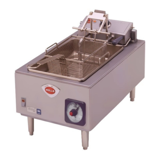
Model F58
This manual is considered to be part of the appliance and is to be given to the OWNER or
MANAGER of the restaurant, or to the person responsible for TRAINING OPERATORS of
this appliance. Additional manuals are available from your WELLS DEALER.
THIS MANUAL MUST BE READ AND UNDERSTOOD BY ALL PERSONS USING OR
INSTALLING THIS APPLIANCE. Contact your WELLS DEALER if you have any
questions concerning installation, operation or maintenance of this equipment.
2M-307589
p/n
Rev. B
WELLS BLOOMFIELD, LLC
10 Sunnen Drive P.O.Box 430195
St. Louis, MO
telephone: 314-781-2777
fax: 314-781-2714
www.wellsbloomfield.com
Model F88
IMPORTANT: DO NOT DISCARD THIS MANUAL
PRINTED IN UNITED STATES OF AMERICA
63143 USA
OWNERS MANUAL
COUNTERTOP
ELECTRIC
AUTOLIFT
INSTALLATION
USE & CARE
EXPLODED VIEW
PARTS LIST
WIRING DIAGRAM
302
FRYERS
MODELS
F58
F68
F88
Includes
09
M302
0407 rms
Advertisement

Related Manuals for Wells F58


Summary of Contents for Wells F58
-
Page 1: Exploded View
Additional manuals are available from your WELLS DEALER. THIS MANUAL MUST BE READ AND UNDERSTOOD BY ALL PERSONS USING OR INSTALLING THIS APPLIANCE. Contact your WELLS DEALER if you have any questions concerning installation, operation or maintenance of this equipment. -
Page 2: Shipping Damage Claim Procedure
The for information and other details concerning warranty. prices charged by Wells Bloomfield for its products are SERVICE POLICY AND PROCEDURE GUIDE and ADDITIONAL WARRANTY EXCLUSIONS Resetting of safety thermostats, circuit breakers, over cleaning schedules, are customer responsibility. -
Page 3: Table Of Contents
PARTS & SERVICE CUSTOMER SERVICE DATA INTRODUCTION Thank You for purchasing this Wells Bloomfield appliance. Proper installation, professional operation and consistent maintenance of this appliance will ensure that it gives you the very best performance and a long, economical service life. -
Page 4: Features & Operating Controls
FEATURES & OPERATING CONTROLS TEMPERATURE ELEMENT HEAD CONTROL (SHOWN LOWERED) KNOB HEATING INDICATOR HI-LIMIT HI-LIMIT TRIPPED RESET INDICATOR ELEMENT HEAD (SHOWN RAISED) FRYER BASKET BASKET LIFT ELEMENT LIFTING HANDLE ELEMENT SUPPORT FRYPOT HANDLES FRYPOT FUSE FUSE HOLDER POWER SWITCH (except F-68) CAUTION: NAMEPLATE Electric Shock Hazard... -
Page 5: Precautions & General Information
PRECAUTIONS AND GENERAL INFORMATION DANGER: SEVERE BURN HAZARD Contact with hot oil will cause severe burns. Always wear protective clothing and heat resistant gloves when operating the fryer or filtering the oil. WARNING: ELECTRIC SHOCK HAZARD All servicing requiring access to non-insulated components must be performed by qualified service personnel. -
Page 6: Agency Listing Information
AGENCY LISTING INFORMATION This appliance conforms to NSF Standard 4 for sanitation only if installed in accordance with the supplied Installation Instructions and STD 4 maintained according to the instructions in this manual. This appliance is Listed under UL File E6070 for 208V and 240V. E6070 INSTALLATION NOTE: DO NOT discard... - Page 7 INSTALLATION (continued) WARNING: ELECTRIC SHOCK HAZARD All servicing requiring access to non-insulated electrical components must be performed by a factory authorized technician. DO NOT open any access panel which requires the use of tools. Failure to follow this warning can result in severe electrical shock. CAUTION: FRYER ELECTRICAL INSTALLATION RISK OF...
-
Page 8: Operation
OPERATION DANGER: BURN HAZARD Contact with hot oil will cause severe burns. Always wear protective clothing and heat resistant gloves when operating the fryer. CAUTION: NORMAL OPERATION HOT SURFACE 1. a. Be sure TEMPERATURE CONTROL KNOB is turned to OFF. b. -
Page 9: Cleaning Instructions
CLEANING INSTRUCTIONS DANGER: BURN HAZARD Contact with hot oil will cause severe burns. Allow the fryer to cool before cleaning. Always wear protective clothing and heat resistant gloves when cleaning the fryer. PREPARATION CAUTION: Turn temperature control and heat switch OFF Allow fryer to cool completely before cleaning ELECTRIC Unplug fryer from receptacle before cleaning... - Page 10 DISPOSAL OF USED OIL DANGER: BURN HAZARD Contact with hot oil will cause severe burns. Allow the fryer to cool before cleaning. Always wear protective clothing and heat resistant gloves when handling hot oil. PREPARATION CAUTION: Turn temperature control and heat switch OFF Allow fryer to cool completely before draining BURN HAZARD FREQUENCY...
-
Page 11: Troubleshooting Suggestions
Not plugged in or circuit breaker Plug into proper receptacle tripped Reset circuit breaker Fuse blown Contact Wells Authorized Service Agency for repairs Heat switch not ON Press heat switch ON Temperature control knob not set to Set to desired temperature... -
Page 12: Maintenance
MAINTENANCE Periodic cleaning is PERIODIC CLEANING necessary to remove Add 1/2 cup of granulated dishwasher detergent to frypot. Fill with water carbonization from the to MAX OIL line. elements and frypot. Lower element into the frypot. Press heat switch ON and set Frypot may be cleaned by temperature control knob to 225ºF. -
Page 13: Exploded View & Parts List
505658 50231 2 places 51145 (pk 6) 2 places 51146 51259 50233 51040 50198 50543 50205 50207 51048 50222 4 places (pk 10) (pk 10) 4 places 50876 50878 2 places 50850 50215 Wells: Fryer Autolift Exploded View IL1728 4/6/09... - Page 14 EXPLODED VIEW & PARTS LIST F58 COUNTERTOP SINGLE-HEAD AUTOLIFT FRYER - FRY HEAD COMPONENTS HEAD ASSY COMPLETE, F-58 506902 (208V) 506903 (240V) 50176 fiber washer (pk 10) 57882 50177 lock washer 50172 55510 50516 amber temp control 50157 51157 62504...
- Page 15 EXPLODED VIEW & PARTS LIST F58 COUNTERTOP SINGLE-HEAD AUTOLIFT FRYER - CABINET COMPONENTS 20161 1/2 size 20162 full size 50183 53890 20169 (pk 10) 52806 51717 (pk 40) BASKET HOOKS see page 11 53068 54005 55736 (pk 10) green KEPS...
- Page 16 EXPLODED VIEW & PARTS LIST F68 COUNTERTOP DUAL-HEAD AUTOLIFT FRYER - FRY HEAD COMPONENTS HEAD ASSY COMPLETE, F-68 NOTE: Fryer has two identical 62919 (208V) fryer heads. Only one is shown. 62920 (240V) 50177 fiber washer 50176 54066 lock washer (pk 10) 50516 50172 amber...
- Page 17 EXPLODED VIEW & PARTS LIST F68 COUNTERTOP DUAL-HEAD AUTOLIFT FRYER - CABINET COMPONENTS 20161 1/2 size 21062 full size 53890 (pk 10) 51717 (pk 40) 52806 50183 20169 53245 53895 BASKET HOOKS 2 places 53068 see page 11 54005 55736 (pk 10) green KEPS 50231...
- Page 18 EXPLODED VIEW & PARTS LIST F88 COUNTERTOP DUAL-HEAD AUTOLIFT FRYER - FRY HEAD COMPONENTS HEAD ASSY, COMPLETE, F-88 NOTE: Fryer has two identical 62926 (208V) fryer heads. Only one is shown. 62927 (240V) 50177 fiber washer 57882 50176 lock washer (pk 10) 55510 50172 temp control...
- Page 19 EXPLODED VIEW & PARTS LIST F88 COUNTERTOP DUAL-HEAD AUTOLIFT FRYER - CABINET COMPONENTS 20161 1/2 size 20162 full size 53980 (pk 10) 51717 (pk 40) 52806 20169 50183 50183 53245 53895 50131 61974 53068 BASKET 51053 54005 HOOKS (pk 100) 2 places see page 11 55736...
-
Page 20: Wiring Diagram
WIRING DIAGRAM TERMINAL BLOCK POWER SWITCH CONTROL T'STAT HI-LIMIT T'STAT TEMP LIGHT (AMBER) HI-LIMIT GROUND RELAY TROUBLE LIGHT (RED) black FLAME SENSOR N.O. TERMINAL BLOCK* *REMOVE JUMPER WHEN LIFT HEATING EXTERNAL CONTROL IS MOTOR ELEMENT USED. N.C. IMPORTANT: DO NOT CONNECT ANY LIFT POSITION POWER TO FLAME MICRO-SWITCH... - Page 21 WIRING DIAGRAM TERMINAL BLOCK 3 PHASE HI-LIMIT T'STAT CONTROL THERMOSTAT HI-LIMIT T'STAT CONTROL THERMOSTAT TROUBLE TROUBLE LIGHT (RED) LIGHT (RED) HI-LIMIT RELAY HI-LIMIT COIL COIL GROUND TEMP LIGHT TEMP LIGHT RELAY (AMBER) (AMBER) HEATING HEATING ELEMENT ELEMENT black black N.O. N.O.
- Page 22 WIRING DIAGRAM *REMOVE JUMPER WHEN TEMP LIGHT TEMP LIGHT TEST/TROUBLE TEST/TROUBLE EXTERNAL CONTROL IS (AMBER) (AMBER) LIGHT (RED) LIGHT (RED) USED. RIGHT LEFT IMPORTANT: HEATING HEATING DO NOT CONNECT ANY ELEMENT ELEMENT POWER TO FLAME SENSOR TERMINAL CONTROL CONTROL BLOCK! THERMOSTAT THERMOSTAT HI-LIMIT...
-
Page 23: Parts & Service
CRUMB CRADLE 20690 authorized replacement parts, COVER, FRYPOT 21010 contact your Wells authorized LEGS, ADJUSTABLE (Set of 4) 20563 service agency, or call: Wells Bloomfield, LLC 10 Sunnen Dr., P.O.Box 430129 St. Louis MO 63143 USA Service Dept. - Page 24 Commercial Food Equipment Service Association Wells Bloomfield proudly supports CFESA Commercial Food Equipment Service Association SERVICE TRAINING - QUALITY SERVICE SERVICE TRAINING - QUALITY SERVICE Genuine Parts Protect - YOU - All - Ways CUSTOMER SATISFACTION CUSTOMER SATISFACTION WELLS BLOOMFIELD, LLC 10 Sunnen Drive P.O.Box 430195...
Need help?
Do you have a question about the F58 and is the answer not in the manual?
Questions and answers