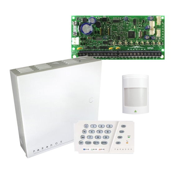
Paradox Esprit 728ULT Programming Manual

Paradox Esprit 728ULT Programming Manual

4 to 32 zone security systems
Hide thumbs Also See for Esprit 728ULT:

Advertisement

4 to 32 Zone Security Systems
PARADOX.COM
Esprit E55 V2.0
Esprit E65 V2.1
Always Armed,
Never Disarmed
Programming Guide

Advertisement

Table of Contents
loading
Need help?

Need help?

Do you have a question about the Esprit 728ULT and is the answer not in the manual?

Questions and answers

Subscribe to Our Youtube Channel

Summary of Contents for Paradox Esprit 728ULT

  • Page 1 4 to 32 Zone Security Systems Esprit E55 V2.0 Esprit E65 V2.1 Always Armed, Never Disarmed Programming Guide PARADOX.COM...
  • Page 2 © 2008 Paradox Security Systems Ltd. All rights reserved. Specifications may change without prior notice. Esprit, Esprit E55 and Esprit E65 are trademarks or registered trademarks of Paradox Security Systems Ltd. or its affiliates in Canada, the United States and/or other...
  • Page 3: Table Of Contents

    Min. = 29mA / Max. = 31mA * When using a K636 keypad, only partition 1 is available. To use both partitions, use a K10V/H, K32, or K32I keypad. Comparison Chart Feature Esprit E55 Esprit E65 Esprit 728ULT StayD Maximum Zones* On-board Zones Keypad Zones Partitions**...
  • Page 4: Entering Programming Mode

    Entering Programming Mode Press [ ENTER Enter your [ ] (default: 000000) or [ ] (no default). [ ] and [ ] lights flash. INSTALLER CODE MAINTENANCE CODE STAY To modify codes, see System Codes on page 31. Enter 3-digit [ ] you wish to program.
  • Page 5: Viewing Version Numbers

    Decimal and Hexadecimal Values What Do I See? Value or Action What Do I Press? 10-zone LED 32-zone LED Value 0 / Replace Current Erase digit and remain in section Erase digit and remain in section SLEEP Digit with 0 Values 1 to 9 [1] to [9] Erase digit and remain in section...
  • Page 6: System Planning

    System Planning Path Zone Serial # Sticker Description Path Zone Path Zone Path Zone (Entry Point) Keypad 1 / ZX8 / ZX8SP Keypad 2 / ZX8 / ZX8SP Keypad 3 / ZX8 / ZX8SP Keypad 4 / ZX8 / ZX8SP Keypad 5 / ZX8 / ZX8SP Keypad 6 / ZX8...
  • Page 7: Zone Programming

    Zone Programming See Quick Menus on page 39 To program zone definitions, zone partitions and assign options: Zone Recognition When expanding zones via ZX8, up to 3 ZX8 modules can be added to the system and are identified by the ZX8 3-position jumpers +1, +9 and +17.
  • Page 8: Zone Definitions

    Zone Definitions To program zone definitions, zone partitions and assign options: Step Action Details ] + [ ] + [ ] = flash. [ ] may also be used. ENTER INSTALLER CODE STAY MAINTENANCE CODE (default: 0000 / 000000) Enter 3-digit zone you wish to program ] + [ ] = on (see table on page 7) STAY...
  • Page 9 Partition (For a one-partition system, Zone use K636 keypads. For a Section Zone* Zone Options Definition two-partition system, use K10V/H, K32, or K32I keypads.) [001] Zone 1: __________________________ _____/_____ ________ 1 2 3 4 5 6 7 8 [002] Zone 2: __________________________ _____/_____ ________ 1 2 3 4 5 6 7 8...
  • Page 10 [705] General Zone Options 1 Option ATZ zone doubling Disabled Enabled ATZ wiring options Series Parallel [3]+[4] Tamper Recognition Keypad Bus Tamper Recognition Options* Keypad / Bus Module Tamper Recognition Options* OFF Disabled Disabled Trouble only Trouble only OFF When disarmed: Trouble only TROUBLE ONLY When armed: Follow zone’s alarm type...
  • Page 11 Section Data Description (Default 060) [054] Zone 14 (Z5 with ATZ): ____/____/____ (000 to 255) x 10ms Hardwire Zone 14 Speed [055] Zone 15 (Z6 with ATZ): ____/____/____ (000 to 255) x 10ms Hardwire Zone 15 Speed [056] Zone 16 (Z7 with ATZ): ____/____/____ (000 to 255) x 10ms...
  • Page 12: Keypad Programming

    Keypad Programming Keypad Zone Number Assignment Step Action Details ] + [ ] + [ ] = flash. [ ] may also be used. ENTER INSTALLER CODE STAY MAINTENANCE CODE (default: 0000 / 000000) ] + [ ] = on STAY Press and hold (3sec)
  • Page 13: Partition Programming

    [704] Keypad Options Option Bell squawk when arm/disarm with a keypad Disabled Enabled Beep on exit delay Disabled Enabled No exit delay beeps and no bell squawk when stay/sleep Disabled Enabled Keypad Lockout Data Description [716] ____/____/____ (000 to 255) minutes Keypad lockout delay (default 000) [717] ____/____/____...
  • Page 14: System Programming

    Section Data Description [749] ____/____/____ (000 to 255) x 15 minutes Partition 1 no movement (default 000) [750] ____/____/____ (000 to 255) x 15 minutes Partition 2 no movement (default 000) Section Data Description [761] ____/____:____/___ HH: MM Auto-arm on time Partition 1 (default 00:00) [762] ____/____:____/____ HH: MM...
  • Page 15: Communication Programming

    Communication Programming [800] Dialer Options Option [1]+2]* See Table See Table Telephone Line Monitoring (TLM) Options Disabled When disarmed: Trouble only When armed: Trouble only When disarmed: Trouble only When armed: Audible alarm Silent alarms become Audible alarm [3]* Disabled Enabled Switch to pulse on 5 attempt...
  • Page 16: Communication Settings

    [803] Event Call Direction Options 2 Option Call tel. #1 for tamper/restore report codes Disabled Enabled Call tel. #2 for tamper/restore report codes Disabled Enabled Call pager for tamper/restore report codes Disabled Enabled Call tel. #1 for trouble/restore report codes Disabled Enabled Call tel.
  • Page 17 Special Keys for Telephone Numbers Press Action or Value switch from pulse to tone dialing or vice versa 4-second pause deletes current digit SLEEP inserts blank space Communication Timers Section Data Description [830] ____/____/____ (000 to 255) x 2 seconds TLM fail delay (default 016) [831] ____/____/____...
  • Page 18 Communication Restore Report Codes [881] ____/____ GSM RF jam [882] ____/____ ____/____ GSM no service ____/____ IP100 no service* ____/____ GSM module supervision lost ____/____ IP100 supervision lost* ____/____ GPRS receiver fail to communicate* ____/____ IP receiver fail to communicate* * E65 panels only VDMP3 Options [703]...
  • Page 19 PCS100 Programming [805] GSM Options Option GSM Reporting* Primary Backup * Options are only available on the Landline Landline [1] & [2] E55 control panel. The E65 will only Landline communicate via GSM. Landline [3] & [4] Future use GSM No Service Trouble Feedback Disabled [5] &...
  • Page 20 IP / GPRS Reporting Account Settings (E65 panels only) IP Account Numbers [918] ___/___/___/___ . 1234) IP ACCOUNT PARTITION [919] ____/___/___/___ . 1234) IP ACCOUNT PARTITION IP Receiver 1 Configuration [929] ___/___/___ . ___/___/___ . ___/___/___ . ___/___/___ . 100.100.100.100) “0”...
  • Page 21: Programmable Output Programming

    [948] ___/___ . 01) IP PROFILE [949] IP RECEIVER STATUS (see Table 6 on page 19) VIEW STATUS TO REGISTER PRESS Table 6: IP/GPRS Registration Status (E65 panels only) Main Menu Trouble Sub-Menu Trouble Menu [1] IP/GPRS module registration status [1] OFF = Unregistered [1] Slow Flash = Registering...
  • Page 22: Stayd

    Event Description Event Group # Sub-group # 00 = Zone OK 01 to 32 = Zone number 01 = Zone open 99 = Any zone number 02 = Partition status 00 to 01= N/A 02 = Silent alarm 03 = Buzzer alarm 04 = Steady alarm 05 = Pulsed alarm 06 = Strobe...
  • Page 23: Stayd

    Event Group # Sub-group # 26 = Software Access (VDMP3, IP100, NEware, WinLoad) 00 = Non-valid source ID 01 = WinLoad direct 02 = WinLoad through IP module 03 = WinLoad through GSM module 04 = WinLoad through modem 05 = NEware direct 06 = NEware through IP module 07 = NEware through GSM module 08 = NEware through modem...
  • Page 24: Partitions

    Event Group # Sub-group # 44 = New trouble 00 = N/A (Partition 1 only except sub-group 07 = both partitions) 01 = AC failure 02 = Battery failure 03 = Auxiliary current overload 04 = Bell current overload 05 = Bell disconnected 06 = Clock loss 07 = Fire loop trouble 08 = Fail to communicate to monitoring station telephone #1...
  • Page 25: Partitions

    Event Group # Sub-group # 49 to 56 = N/A 58 = Zone forced 01 to 32 = Zone number 59 = Zone included 99 = Any zone number 64 = System Status 00 = Follow Arm LED status*: 1. PGM pulse fast in alarm 2.
  • Page 26: System Report Codes

    Programmable Output Delays & Recognition Section Data Default = 005 [281] PGM 1: (E55/E65 onboard) ___/___/___ (000 to 255 x 1 sec./mins.) [282] PGM 2: (E65 onboard) ___/___/___ (000 to 255 x 1 sec./mins.) [283] PGM 3: (E65 onboard) ___/___/___ (000 to 255 x 1 sec./mins.) [286] PGM 6: (ZX8 ID =+1)
  • Page 27 Special Disarming Report Codes (Default = FF) Section Data Description [862] _____/_____ Cancel auto-arm _____/_____ Disarming via PC _____/_____ Cancel alarm with user or WinLoad _____/_____ Cancel parademic Special Alarm Report Codes ( Default = FF Section Data Description Section Data Description [863]...
  • Page 28: Ademco Contact Id Report Codes

    Section Data Description Section Data Description ____/____ Test report ____/____ Installer out ____/____ ____/____ Closing Delinquency ____/____ WinLoad out ____/____ [878] _____/_____ Disarm with keyswitch Disarm with keyswitch after _____/_____ alarm Alarm cancelled with key- _____/_____ switch _____/_____ NOTE: For reporting code format instructions, see page 24. NOTE: Refer to Decimal and Hexadecimal Values on page 3.
  • Page 29 CID# Reporting Code Programming CID# Reporting Code Programming CID# Reporting Code Program- Value Value ming Value General Alarms - 140 311 Battery missing/dead 376 Hold-up zone trouble 140 General alarm 312 Power supply over current 377 Swinger trouble limit 141 Polling loop open 313 Engineer reset 378 Cross-zone trouble 142 Polling loop short...
  • Page 30: Automatic Report Code List

    CID# Reporting Code Programming CID# Reporting Code Programming CID# Reporting Code Program- Value Value ming Value 426 Access door propped open 8E 552 Radio transmitter disabled B4 427 Access point door status Bypasses - 570 monitor trouble Access point request to exit 570 Zone bypass Access program mode entry 571 Fire bypass...
  • Page 31 System Event Default Contact ID Report Code Zone shutdown (##) 1 57A - Zone bypass Zone tampered (##) 1 144 - Sensor tamper Zone tamper restore (##) 3 144 - Sensor tamper restore AC failure 1 3A1 - AC loss Battery failure 1 3A9 - Battery test failure Auxiliary supply trouble...
  • Page 32: Installer Function Keys

    Installer Function Keys To access the Installer Function keys, press: ] + [ ] = Test Report: Send the “Test Report” report code programmed in section [875] (page 25) to the ENTER INSTALLER CODE monitoring station. ] + [ ] = Cancel Communication: Cancels all communication with the WinLoad software or with the ENTER INSTALLER CODE STAY...
  • Page 33: User Programming

    User Programming See Quick Menus on page 39 System Codes [701] General System Options Option Access code length 6 digits 4 digits Lock master code Disabled Enabled Section Data Description [395] ____/____/____(147 to lock, other to unlock) Installer Code Lock (default 000) [397]* ____/____/____/____/____/____ Installer Code (default = 000000)*...
  • Page 34 User Report Codes ( Default = FF) [966] Clear User Report Codes Option Clear user report codes* Disabled Enabled * Press [ ] to reset the respective set of report codes to default before exiting the section. ENTER [967] Reset User Report Codes Option Reset user report codes to default* Disabled...
  • Page 35: Hardware Connections

    Hardware Connections Single Zone Inputs NOTE: Keyswitches are connected as standard zones and will follow ATZ options programmed in section [705] options [1] and [2] on page 8. Esprit E55 / E65...
  • Page 36 Advanced Technology Zone (ATZ) Connections Programming Guide...
  • Page 37 Connecting Fire Circuits Single Fire Zone Connections Only If the ATZ feature is enabled, do not use the extra input (i.e. in the above example, input 005 cannot be used as a zone). NOTE: It is recommended that the smoke detectors be connected in a daisy chain configuration. Alarm Relay and PGM Connections PGM Power Source + terminal...
  • Page 38: Connecting To Winload

    From the Select Firmware drop-down box, select the firmware version you wish to install. If you have already downloaded the .pef file from paradox.com, click the [...] button and select the location of the .pef file. Click the Update product firmware button.
  • Page 39 E55 PCB Layout port used for voice reporting Paradox Memory Key Status LED: DIALER EBUS VDMP3 (PMC-4, PMC5) • Flash once every second = Normal with the plug-in voice module. • Flashes ON 1 second and OFF 1 second = Any trouble...
  • Page 40 • Fast flash 6 seconds after power up PCS100. = Installer lock enabled Refer to AC Power & Paradox Memory Key Backup Battery (PMC-4, PMC5) Connections on page 35. Refer to PGM Used for connecting the IP100 Connections on page 35.
  • Page 41: Installer Quick Menu

    Installer Quick Menu Zones Step Action Details = flash. Programmed zones are lit (button or LED depending on keypad). INSTALLER CODE ] may also be used. MAINTENANCE CODE 2 digits: 01 to 32 ZONE NUMBER Wireless zone = open/close cover or press learn/tamper switch. Hardwired zone = NROLL OR ERASE ZONE Press [ ].
  • Page 42: Walk Test Mode

    Walk Test Mode Step Action Details = flash. [ ] may also be used. INSTALLER CODE MAINTENANCE CODE Activates or deactivates Walk Test Mode. Installer and Maintenance Codes Step Action Details = flash. INSTALLER CODE [7] = Installer Code [8] = Maintenance Code Enter 4- or 6-digit code.* To erase a code, press the [ ] key for 3 seconds.
  • Page 43 Communicator Step Action Details = flash. [ ] may also be used, however, it cannot modify the INSTALLER CODE MAINTENANCE CODE backup phone number. [2] = Backup Phone # [3] = Personal Phone #1 [4] = Personal Phone #2 [5] = Personal Phone #3 [6] = Personal Phone #4 [7] = Personal Phone #5 [8] = Pager #...
  • Page 44 Index 950 ..............2 955 ..............2 966 ..........9, 15, 24, 32 Sections 967 ..........9, 15, 24, 32 001 to 032 ............7 970 ............. 2, 31 041 to 056 ............8 975 ............. 2, 31 141 to 172 ............9 980 ..............
  • Page 45 Disarming Report Codes ........ 25 Panic Options ..........12 DTMF Dialing ..........13 Partition ............11 Timers Partitioning ............. 11 Entry delay - Display on LCD keypad ..... 10 PCB Layout ..........37, 38 Event Call Direction Options ......13 PCS100 Exit delay termination ........
  • Page 46 ........12 Flex-Instant delay Trouble Display ..........30 ..........12 Re-arm delay Switch to Pulse ..........13 User Code Options ......... 31 System Special Report Code ......25 User Programming ......... 31 System specifications ....... 37, 38 System Timers ..........15 System Trouble VDMP3 ..........
  • Page 48 Canada and the U.S., call 00-1-450-491-7444, Monday to Friday from 8:00 a.m. to 8:00 p.m. EST. Please feel free to visit our website at www.paradox.com We hope this product performs to your complete satisfaction. Should you have any questions or comments, please visit www.paradox.com.

This manual is also suitable for:

Esprit e65Esprit e55

Table of Contents