Table of Contents
Advertisement
Quick Links
Download this manual
See also:
User Manual
Revision: April 3, 2012
™
Lexmark
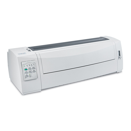
Forms Printer 2500+ series
2580+, 2581+, 2590+, 2591+
• Table of contents
• Start diagnostics
• Safety and notices
• Trademarks
• Index
Lexmark and Lexmark with diamond design are
trademarks of Lexmark International, Inc., registered
in the United States and/or other countries.
Advertisement
Table of Contents


Need help?
Do you have a question about the 2591+ and is the answer not in the manual?
Questions and answers