Table of Contents
Advertisement
Quality Assurance
Certificate Reg. No:
04 100 950420
Subject to change without notice
Manufacturing point: Jeddah, Saudi Arabia
Nearest port of embarkation: Jeddah Islamic port
Product classification: Commercial
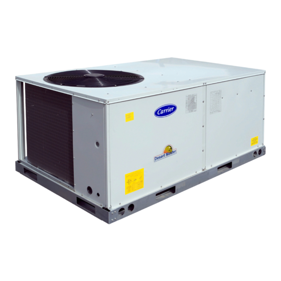
The 50TCM units are single side discharge rooftop cooling unit utilizing electric heat as an option. Units are pre-
wired, pre-charged with R-410A refrigerant, and tested at the factory. These units can be placed on the side of a
building or can be placed on a roof without roof curbs. Each unit is designed to occupy a minimal space. Piping and
drain connections are readily accessible.
Contact your local Carrier representative for additional reference materials.
50TCM – 50Hz
Nominal Cooling Capacity 6 – 12.5 Tons
HFC R - 410A Refrigerant
Page 1
Package Rooftop Units – 50Hz
Installation, Operation and Maintenance
Advertisement
Table of Contents

Related Manuals for Carrier 50TCM Series


Summary of Contents for Carrier 50TCM Series
- Page 1 R-410A refrigerant, and tested at the factory. These units can be placed on the side of a building or can be placed on a roof without roof curbs. Each unit is designed to occupy a minimal space. Piping and drain connections are readily accessible. Contact your local Carrier representative for additional reference materials. Page 1...
-
Page 2: Table Of Contents
Table of Contents 1.0 – SAFETY CONSIDERATIONS ..........................3 1.1 – General ..............................3 1.2 – Installation Safety Considerations ......................3 1.3 – Warranty ..............................3 Unit Physical Data ..............................5 Unit Dimensional Drawing ............................6 2.0 – INSTALLATION ..............................12 2.1 –... -
Page 3: Safety Considerations
Warranty is based on the general terms and conditions of the manufacturer. Any modifications to the design and/or installation made without discussion with Carrier and without advance written agreement will result in the loss of the right to any warranty claims and any claim for injury to personnel as a result of these modifications. - Page 4 WARNING ELECTRICALSHOCK HAZARD Failure to follow this warning could cause personal injury, death and/or equipment damage. Before performing service or maintenance operations on unit, always turn off main power switch to unit and install lockout tag. Unit may have more than one power switch. WARNING UNIT OPERATION AND SAFETY HAZARD Failure to follow this warning could cause personal injury, death...
-
Page 5: Unit Physical Data
Table 1 - Unit Physical Data (English) Unit 50TCM Unit Dimensions - (in) 41.3x74.3x46.7 41.2x88.1x59.4 49.3x88.1x59.4 Unit Operating Weight - (LBS) 1078 Refrigeration System Compressor No.# / Type 1 / Scroll 2 / Scroll Refrigerant type Puron ® R410A Circuts No.# Charge per Circuit (1-Down/2-Up) - (LBS) 15.43 8.71/8.82... -
Page 6: Unit Dimensional Drawing
Page 6... - Page 7 07 (cont.) 48--- in (1219 mm) Unit disconnect is mounted on panel 18--- in (457 mm) No disconnect, convenience outlet option 18--- in (457 mm) Recommended service clearance 12--- in (305 mm) Minimum clearance 42--- in (1067 mm) Surface behind servicer is grounded (e.g., metal, masonry wall) 36--- in (914 mm) Surface behind servicer is electrically non--- conductive (e.g., wood, fiberglass) Special...
- Page 8 Page 8...
- Page 9 (cont.) 48--- in (1219 mm) Unit disconnect is mounted on panel 36--- in (914 mm) If dimension--- B is 12--- in (305 mm) 18--- in (457 mm) No disconnect, convenience outlet option 18--- in (457 mm) Recommended service clearance (use electric screwdriver) 12--- in (305 mm) Minimum clearance (use manual ratchet screwdriver) 12--- in (305 mm)
- Page 10 Page 10...
- Page 11 cont C10329 C08337 48--- in (1219 mm) Unit disconnect is mounted on panel 18--- in (457 mm) No disconnect, convenience outlet option 18--- in (457 mm) Recommended service clearance 12--- in (305 mm) Minimum clearance 42--- in (1067 mm) Surface behind servicer is grounded (e.g., metal, masonry wall) 36--- in (914 mm) Surface behind servicer is electrically non--- conductive (e.g., wood, fiberglass) Special...
-
Page 12: Installation
2.0 – INSTALLATION 2.1 – Jobsite Survey Complete the following checks before installation. 1. Consult local building codes or the U.S.A. National Electrical Code (Ref: ANSI/NFPA 70, [American National Standards Institute/National Fire Protection Association], latest revision) for special installation requirements. 2. -
Page 13: Positioning And Clearance
Roof mount - Check building codes for weight distribution requirements. Unit weight and dimensions is shown in unit dimensional drawing and Table 2. DIMENSIONS Max Weight UNIT 50TCMA07 74.4 1888 38.0 41.4 1051 50TCMD08 1410 88.0 2235 41.0 1040 41.5 1055 50TCMD09 1525... -
Page 14: Field Fabricate Ductwork
2.6 – Field Fabricate Ductwork Secure all ducts to building structure. Use flexible duct connectors between unit and ducts as required (a space for 2.5 to 3ft is required in case of repairing or replacing the blower wheel). Insulate and weatherproof all external ductwork, joints, and roof openings with counter flashing and mastic in accordance with applicable codes. - Page 15 Electrical Data Table to determine the percent of voltage imbalance. Operation on improper lines voltage or excessive phase imbalance constitutes abuse and may cause damage to electrical components. Such operation would invalidate any applicable Carrier warranty. Page 15...
-
Page 16: Start-Up Instructions
Field Control Wiring – The 50TCM unit requires an external temperature control device. This device can be a thermostat (field--supplied) or a PremierLink controller (field--installed accessory, for use on a Carrier Comfort Network or as a standalone control) Thermostat – Install a Carrier--approved accessory thermostat according to installation instructions included with the accessory. -
Page 17: Compressor Rotation
3.5 – Compressor Rotation It is important to be certain the compressors are rotating in the proper direction. To determine whether or not compressors are rotating in the proper direction: 1. Connect service gages to suction and discharge pressure fittings. 2. -
Page 18: Service
Table – 3 Fan RPM at Motor Pulley Settings Unit MOTOR PULLEY TURNS OPEN - ENGLISH Freq. Drive Package 50TCM 1 1/3 2 1/3 3 1/3 4 1/3 1211 1176 1140 1104 1069 1033 Standard Static 1449 1362 1330 1298 1267 1235 1203... -
Page 19: Evaporator Fan Performance Adjustment
CAUTION UNIT DAMAGE HAZARD Failure to follow this caution may result in damage to components. 1. The compressor is in a Puron® refrigerant system and uses a (POE) lubricant Emkarate RL 32 3MAF. In the field the oil level could be topped up with Mobil EAL Arctic 22 CC if 3MAF is not available. POE oil is extremely hygroscopic, meaning it absorbs water readily. -
Page 20: Belt Tension Adjustment
Fig. 10 Condenser – Fan Adjustment 4.7 – Refrigerant Charge Amount of refrigerant charge is listed on unit nameplate and in Table 1. Refer to Carrier GTAC II; Module 5; Charging, Recovery, Recycling, and Reclamation section for charging methods and procedures. Unit panels must be in place when unit is operating during charging procedure. -
Page 21: Protective Devices
This control circuit is protected against over-current by a circuit breaker. Breaker can be reset manually if it trips, determine cause of trouble before resetting. 5.0 – REPLACEMENT PARTS A complete list of replacement parts may be obtained from any Carrier distributor. Page 21... -
Page 22: Electrical Data
Table 4 - Electrical Data 50TCM Compressor Electric Heater No.1 No.2 Drive Power MOCP Unit Size package Supply Application RLA LRA RLA LRA Qty HP FLA HP Heater P.N Indoor Motor V / Ph / Hz (KW) 10.6 74.0 1/3 1.6 17.5 10.6 74.0 1/3 1.6... - Page 23 Table 4 - Electrical Data (Continued) 50TCM Compressor Electric Heater No.1 No.2 Drive Power MOCP Unit Size package Supply Application RLA LRA RLA LRA Qty HP FLA HP Heater P.N Indoor Motor V / Ph / Hz (KW) 7.8 51.5 7.8 51.5 23.6 7.8 51.5 7.8 51.5 CRHEATER116A00...
-
Page 24: Typical Wiring Schematic
Typical Wiring Schematic 50TCMA07 400V Page 24... - Page 25 Typical Wiring Schematic 50TCMD08-09 400V Page 25...
- Page 26 Typical Wiring Schematic 50TCMD12-14 400V Page 26...
- Page 27 Typical Control Schematic 50TCMA Series Page 27...
- Page 28 Typical Control Schematic 50TCMD Series Page 28...
-
Page 29: Fan Performance
6. Bold data shows the range of air flow rate for unit management system, other rpms require field-supplied drive. 7. Use of field-supplied motor may affect wiring size. Contact your Carrier representative for details. 8. Conversion - Bhp to KWI Bhp X 0.746... - Page 30 6. Bold data shows the range of air flow rate for unit management system, other rpms require field-supplied drive. 7. Use of field-supplied motor may affect wiring size. Contact your Carrier representative for details. 8. Conversion - Bhp to KWI Bhp X 0.746...
- Page 31 6. Bold data shows the range of air flow rate for unit management system, other rpms require field-supplied drive. 7. Use of field-supplied motor may affect wiring size. Contact your Carrier representative for details. 8. Conversion - Bhp to KWI Bhp X 0.746...
-
Page 32: Cooling Chart
Charging Chart 400V-50Hz 50TCMA07 Charging Chart 400V-50Hz 50TCMD08 CIR # 1 Page 32... - Page 33 Charging Chart 400V-50Hz 50TCMD08 CIR # 2 Charging Chart 400V-50Hz 50TCMD09 CIR # 1 Page 33...
- Page 34 Charging Chart 400V-50Hz 50TCMD09 CIR # 2 Charging Chart 400V-50Hz 50TCMD12 CIR # 1 Page 34...
- Page 35 Charging Chart 400V-50Hz 50TCMD12 CIR # 2 Charging Chart 400V-50Hz 50TCMD14 CIR # 1 Page 35...
- Page 36 Charging Chart 400V-50Hz 50TCMD14 CIR # 2 Page 36...
-
Page 37: R-410A Refrigerant Quick Reference Guide
ATTENTION INSTALLERS AND SERVICE TECHNICIANS! R-410A Refrigerant Quick Reference Guide • R-410A refrigerant operates at 50-70 percent higher pressures than R-22. Be sure that servicing equipment and replacement components are designed to operate with R-410A refrigerant. • R-410A refrigerant cylinders are rose colored. •... -
Page 38: Troubleshooting
Troubleshooting Guide Cooling Service Analysis PROBLEM CAUSE REMEDY Compressor and condenser fan will not Power failure. Call power company. start. Fuse blown or circuit breaker tripped. Replace fuse or reset circuit breaker. Defective thermostat, contactor, transformer, or Replace component. control relay. Insufficient line voltage. -
Page 39: Start-Up Checklist
START-UP CHECKLIST (Remove and Store in Job File) I. PRELIMINARY INFORMATION MODEL NO: DATE: SERIAL NO: TECHNICIAN: II. PRE-START-UP (Insert checkmark in box as each item is completed) 1) ALL PACKING MATERIALS HAVE BEEN REMOVED FROM THE UNIT. 2) VERIFY THAT UNIT INSTALLATION IS LEVEL. 3) CONDENSATE CONNECTION IS INSTALLED PER INSTALLATION INSTRUCTION. - Page 40 Manufacturer reserves the rights to discontinue or change at any time, specifications or designs without notice and without incurring any obligations. Supersedes Version: 50TCM-IOM01 Catalog Number: 50TCM-IOM02 Page 40 Effective Date: 12-07-2016 Phase: 50Hz...
Need help?
Do you have a question about the 50TCM Series and is the answer not in the manual?
Questions and answers