EDAN M3 Service Manual
Vital signs monitor
Hide thumbs
Also See for M3:
- User manual (114 pages) ,
- Service manual (20 pages) ,
- User manual (116 pages)

Subscribe to Our Youtube Channel
Related Manuals for EDAN M3


Summary of Contents for EDAN M3
- Page 1 EDAN INSTRUMENTS, INC Manual Ver: V1.0 Release Date: Aug. 2008 Part Number: MS1R-109399-V1.0...
- Page 2 EDAN INSTRUMENTS INC. (hereinafter called EDAN) owns all rights to this unpublished work and intends to maintain this work as confidential. EDAN may also seek to maintain this work as an unpublished copyright. This publication is to be used solely for the purposes of reference, operation, maintenance, or repair of our equipment.
-
Page 3: Revision History
Using This Label Guide This guide is designed to give key concepts on safety precautions. WARNING A WARNING label advises against certain actions or situations that could result in personal injury or death. CAUTION A CAUTION label advises against actions or situations that could damage equipment, produce inaccurate data, or invalidate a procedure. -
Page 4: Table Of Contents
Table of Contents 1 Introduction......................... 1 1.1 General Information....................1 1.2 Screen Display ....................... 2 1.3 Button Functions..................... 5 1.4 Interfaces........................ 7 1.5 Built-in Rechargeable Battery ................. 9 2 Principle ........................12 General Parts ....................12 2.1.1 Parameter Measuring Part ................12 2.1.2 Main Control Part ................... - Page 5 4 Test and Calculation....................26 Check the Monitor ..................... 26 NIBP Calibration....................26 5 Disassembly Graph ....................28 Disassembly Graph................... 28 Front Shuck Assembly ..................28 Rear Shuck Assembly ..................30 Bracket Assembly ..................... 30 6 Troubleshooting......................32 Device Failures ....................32 Display Failures....................
-
Page 6: Introduction
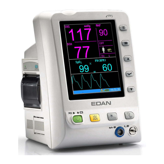
On the LCD display screen, SpO waveform and all the monitoring parameters can be displayed clearly. M3 monitor is a user-friendly device with operations conducted by a few buttons on the front panel. Refer to Button Functions for details. Figure1-1 M3 Vital Signs Monitor... -
Page 7: Screen Display
: Arterial oxygen saturation (SpO Pulse Rate (PR); PLETH (Plethysmogram) The M3 monitor provides extensive functions as visual and audible alarm, recorder and storage for trend data, SpO /NIBP measurements review, net connection, nurse call, alarm events and so on. The recorder, wireless net connection and mobile storage are optional functions for monitor. - Page 8 M3 Vital Signs Monitor Service Manual ② Figure1-3 Main display with data The icons on the interface and their meanings are as follows: Battery status indicator Connected to mains power supply Network connection indicator Network connection off Medium/Low alarm icon...
-
Page 9: Information Area
M3 Vital Signs Monitor Service Manual Patient type: ADU Patient type: PED Patient type: NEO NIBP manual mode NIBP interval mode NIBP continual mode Heart beat Current patient ID Current time 18:18:55 Parameter Area (①) Parameter area is on the right of Waveform area, and parameters are displayed: ... -
Page 10: Button Functions
M3 Vital Signs Monitor Service Manual Signs indicating the net connection status; Signs indicating the Battery or mains power supply status; Current time; Signs indicating the sensor off or alarm off. Alarm Indicator and Alarm Status -... - Page 11 M3 Vital Signs Monitor Service Manual All the operations to the monitor can be finished by several buttons. ① ON/OFF When the monitor is off, press this button to turn on it. When the monitor is on, press this button and hold for 3s to turn off the monitor;...
-
Page 12: Interfaces
Connectors for cables and sensors are as shown in Figure 1-5. sensor connector ② 1. SpO 2. NIBP cuff connector ③ WARNING Only connect the device to EDAN supplied or recommended accessories. Rear Panel ! This symbol means “BE CAREFUL". Refer to the manual. - 7 -... - Page 13 ① Equipotential grounding terminal for connection with the hospital’s grounding system. ② Power supply socket: AC100 ~ 240 V, 50/60 Hz. ③ Network Interface (reserved): Standard RJ45 Socket, for connecting to MFM-CMS of EDAN. Bottom panel There are battery compartment and fuse box at the bottom panel.
-
Page 14: Built-In Rechargeable Battery
M3 Vital Signs Monitor Service Manual Battery compartment cover Fuse Figure1-7 Bottom panel 1.5 Built-in Rechargeable Battery The monitor is equipped with a built-in rechargeable lithium-ion battery (hereinafter called battery). When switch on AC power supply, the battery will be recharged automatically until full electric energy. - Page 15 M3 Vital Signs Monitor Service Manual For recharging, the battery is 90% to 100% charged after 300min of recharging. Replace Battery During monitoring state or communication state, when the electric energy of battery is low or empty, the battery state icon will display and flash.
- Page 16 M3 Vital Signs Monitor Service Manual disassemble or modify the battery. WARNING Before transporting, the battery should be taken off from monitor. WARNING Please take out the battery before storing the monitor for more than 1 month. - 11 -...
-
Page 17: Principle
M3 Vital Signs Monitor Service Manual 2 Principle 2.1 General Parts The monitor has been designed to measure physiological parameters including NIBP and SpO There are five parts in monitor, see figure 2-1. • Parameter measuring part • Main control part •... -
Page 18: Main Control Part
M3 Vital Signs Monitor Service Manual 2.1.2 Main Control Part Main control board consists of Core board and Interface board. It has CPU/memory, display circuit, network circuit and I/O interface. Main control board of the integrated board is used to drive man-machine interface, manage parameter measurement and provide other specific functions to the user such as configuration storage, waveform and data review, etc. -
Page 19: Power Module
M3 Vital Signs Monitor Service Manual Alarm Speaker Battery board LCD backlight LCD data Keyboard Power module Slave keyboard module sensor Power control board Air pump, NIBP module 2410 Valve, Cuff Main control Wireless board USB board RJ45 module Network board... - Page 20 M3 Vital Signs Monitor Service Manual Battery Power board Power control board Figure2-3 Schematic Diagram of Power Board Principle Introduction This module converts 220V AC mains power supply or battery power into 5V, 12V and -12V DC supplies to power other boards. If AC mains and battery coexist, the former take the priority to power the system and charge the latter at the same time.
-
Page 21: Main Control Board
M3 Vital Signs Monitor Service Manual Voltage Detection Circuit Detects the output voltage of every part in detection circuit, converts analogue signals to digital signals and then send them to Main control board for processing. 2.2.2 Main Control Board Main control board which is consisted of Interface board and Core board, is the heart of monitor, it can do system control, system adapter, system management, data processing, file management, display processing, recorder management, data storage, system diagnosis, fault alarm, etc. -
Page 22: Keyboard
M3 Vital Signs Monitor Service Manual logical control and other functions. RTC can offer second, minute, hour, day, month, year and other calendar information. CPU can gain such calendar information from RTC, it also can rewrite the data in RTC. -
Page 23: Recorder Module
M3 Vital Signs Monitor Service Manual Principle Introduction This module detects key and encoder input signals, converts them into codes and sends to Main control board. Main control board sends command to the keyboard and the latter accordingly control indicator and audio process circuit to realize audio and visual alarm. -
Page 24: Software Function Principle
M3 Vital Signs Monitor Service Manual start printing action. Step Motor Drive Circuit A step motor is used in the recorder to feed paper. This circuit is designed to drive the step motor. Recorder Status Detect Circuit Detect the status of the recorder and send the information to CPU System, including the position of paper platen, whether there is paper, temperature of thermal head. -
Page 25: System Software Function
M3 Vital Signs Monitor Service Manual It indicates software system inner the frame above, on the left of frame is software system input, and on right is software system output; parameter measuring module exchanges data with software system by serial ports, while user communicates with system by keyboard; among the output devices, recorder and alarm devices receive data via serial ports, the analogue output apparatus is MBUS, screen and network controller are controlled directly by CPU. -
Page 26: System Parameters
M3 Vital Signs Monitor Service Manual 2.4 System Parameters 2.4.1 General Parameter module is the basic unit to acquire signals for monitoring parameters in monitor. The results are transmitted to Main control board by keyset to finally accomplish processing and displaying of data and waveforms. -
Page 27: Nibp
M3 Vital Signs Monitor Service Manual 2.4.2 NIBP Blood pressure monitors commonly measure arterial pressure, which is produced by the contraction of the heart and constantly changes over the course of cardiac cycle. Three blood pressure values, expressed in millimeters of mercury above atmospheric pressure, are typical obtained. - Page 28 M3 Vital Signs Monitor Service Manual display the changing light intensity in the form of changing electronic signals. The ratio between the DC and AC of the two types of signals for light is the proportion of oxygen in the blood. Then...
-
Page 29: Installation Of Monitor
M3 Vital Signs Monitor Service Manual 3 Installation of Monitor 3.1 Open the Package and Check Open the package and take out the monitor and accessories carefully. Keep the package for possible future transportation or storage. Check the components according to the packing list. -
Page 30: Connect Sensor To Patient
M3 Vital Signs Monitor Service Manual 3.4 Connect Sensor to Patient Connect all the necessary patient sensors between the monitor and the patient. NOTE: For information on correct connection, refer to related chapters in User manual. 3.5 Check the Recorder If your monitor is equipped with a recorder, open the recorder door to check if paper is properly installed in the slot. -
Page 31: Test And Calculation
Connect all the cables well, then turn on the monitor,the POST (Power-On-Self-Test) is performed automatically. After successfully POST, the EDAN logo will display, then enter the main interface. Check if all the monitoring functions of the monitor can work normally so as to make sure that the monitor is in good condition. - Page 32 M3 Vital Signs Monitor Service Manual authorized by EDAN. NOTE: The calibration of NIBP is just a method for checking the measuring result, it will not change the measuring standard. NIBP Calibration needs T-connector, hose and Thermometer. Calibration procedure: 1. Connect air way as indicated in figure 4-1;...
-
Page 33: Disassembly Graph
5.1 Disassembly Graph 1: M3 Front shuck assembly; 2: Main bracket assembly; 3: M3 rear shuck assembly; 4: Cross recessed countersunk head screw M3×6; 5, 7: Cross recessed round head screw M3×25;... - Page 34 17 18 21 22 23 1, 5, 7: Cross recessed pan head screw M3×6; 2: Main control board; 3: M3 Main control board Insulated gasket; 4: M3 Screen bracket; 6: 5.7 inches LCD; 8, 21, 26: Cross recessed pan head self-tapping screw ST3×8; 9: Main control keyboard; 10: M3 Main control keyboard pressure plate;...
-
Page 35: Rear Shuck Assembly
M3 Vital Signs Monitor Service Manual 5.3 Rear Shuck Assembly 1: M3 rear shuck rubber feet; 2: M3 battery compartment cover; 3: M3 recorder slot cover; 4, 9: Cross recessed pan head self-tapping screw ST3×8; 5: M3 recorder bracket; 6: M3 Rear shuck; 7: Cross recessed pan head self-tapping screw ST2.6×6; 8: Speaker;... - Page 36 1: Label on M3 rear board; 2: Cross recessed countersunk head screw M3×6; 3: M3 rear board; 4: M3 grounding wire pole; 5, 18: Nut M4; 6: AC power supply interface board; 7, 8, 12, 14, 16, 25: Cross recessed pan head screw M3×6; 9: Power board; 10: M3 power module insulated gasket;...
-
Page 37: Troubleshooting
M3 Vital Signs Monitor Service Manual 6 Troubleshooting In transportation, storage and use of monitor, various factors such as unstable network voltage, changing environmental temperature, falling-down or impact, component aging may all result in monitor failures and therefore affect normal application of the device. In failure conditions, professional personnel with the experience of repairing electronic medical devices should perform component-level upkeep for the failure classification listed in the table below. -
Page 38: Display Failures
M3 Vital Signs Monitor Service Manual ④ ④ connection Replace repair power supply or Main connectors control board 6.2 Display Failures Failure Possible cause Solution ①Power ① Replace Power switch board switch board damage When powering on the device, power supply is ②... -
Page 39: Power Board Failures
M3 Vital Signs Monitor Service Manual ① ① Network linking wire is Check repair damaged. network linking wire or HUB. Can not be linked into ② Network bed No. conflicts ② Change bed No. network ③ Main control board failure ③... - Page 40 M3 Vital Signs Monitor Service Manual ① Patient is moving ① eep the patient quiet waveform has ② Environment light is very ② Weaken the light intensity in strong interference. intensive the environment ① Coloring agent has been ① Remove the coloring agent...
-
Page 41: Maintenance And Cleaning
M3 Vital Signs Monitor Service Manual 7 Maintenance and Cleaning 7.1 General Cleaning WARNING Turn off the power and disconnect the line power before cleaning the monitor or the sensor/probe. CAUTION Pay special attention to avoid damaging the monitor: 1) Avoid using ammonia-based or acetone-based cleaners such as acetone. -
Page 42: Cuff Maintenance And Cleaning
M3 Vital Signs Monitor Service Manual Hydrogen Peroxide 3% d. Alcohol Isopropanol ■ Sterilization To avoid extended damage to the equipment, sterilization is only recommended when stipulated as necessary in the Hospital Maintenance Schedule. Sterilization facilities should be cleaned first. -
Page 43: Spo Sensor Maintenance And Cleaning
M3 Vital Signs Monitor Service Manual Figure7-1 Replace Rubber Bag in Cuff To replace the rubber bag in the cuff, first place the bag on top of the cuff so that the rubber tubes line up with the large opening on the long side of the cuff. Now roll the bag lengthwise and insert it into the opening on the long side of the cuff. -
Page 44: Maintenance Menu
Select “MAINTAIN” item in “SYSTEM MENU” to call up “ENTER MAINTAIN PASSWORD” dialog box as shown below, in which you can enter password and then customize maintenance settings. Factory maintenance function is only available for the service engineers of EDAN or representative authorized by EDAN. - Page 45 EXIT: exit the menu. Factory Maintain Factory maintenance function is only available for the service engineers of EDAN or representative authorized by EDAN. Enter factory maintain through password 9 9 8 0.
-
Page 46: Accessories And Ordering Information
M3 Vital Signs Monitor Service Manual 8 Accessories and Ordering Information WARNING The specification of accessories recommended is listed below. Using other accessories may damage the monitor. NOTE: For using neonatal disposable cuff, one NIBP Tube, one connecting tube and one neonatal disposable cuff are necessary. - Page 47 M3 Vital Signs Monitor Service Manual M15-40097 Neonatal Disposable Cuff 5102 (About 6-9cm) M15-40098 Neonatal Disposable Cuff 5104 (About 9-14cm) M13-36036 NIBP Tube (3m) MS1-30437 Connecting Tube for Neonatal Cuff M50R-78035 Printing Paper M21R-064115 Rechargeable Lithium-Ion Battery /HYLB-1049 (14.8V, 4.4 Ah)
-
Page 48: Warranty And Service
Limitation of Warranty Direct, indirect or final damage and delay caused by the following situations for which EDAN are not responsible may void the warranty: ² Groupware is dismounted, stretched or redebugged. - Page 49 M3 Vital Signs Monitor Service Manual EDAN on time. We will, at this option, dispatch the replace one(s) with confirmed shipping invoice. NOTE: (1) Both Return Material Authorization Form and Declaration Form are offered by EDAN service department once the SCF is confirmed by service engineer.
- Page 50 M3 Vital Signs Monitor Service Manual Contact Information If you have any question about maintenance, technical specifications or malfunctions of devices, do not hesitate to contact us. EDAN Instruments, Inc. TEL: +86-755-26898321, 26899221 FAX: +86-755-26882223, 26898330 E-mail: support@edan.com.cn - 45 -...
-
Page 51: Appendixⅰproduct Specification
M3 Vital Signs Monitor Service Manual AppendixⅠProduct Specification A1.1 Classification Anti-electroshock type ClassⅠequipment and internal powered equipment EMC type Class A Anti-electroshock degree , NIBP BF Defibrillation type Ingress Protection IPX1 Working system Continuous running equipment (less than 7 days) A1.2 Specifications... -
Page 52: A1.2.4 Battery
M3 Vital Signs Monitor Service Manual 1 Power On Indicator LED (Green) 1 Alarm Indicator LED (Orange/ Red) 1 Charge Indicator LED (Yellow) 1 Alarm Sound Indicator LED (Backlight) 1 NIBP Working Status Indicator LED (Backlight) 3 Sound Modes correspond to Alarm Mode A1.2.4 Battery... -
Page 53: A1.2.8 Spo
M3 Vital Signs Monitor Service Manual Adult Mode 30~270mmHg 10~220mmHg 20~235mmHg Pediatric Mode 30~235mmHg 10~220mmHg 20~225mmHg Neonatal Mode 30~135mmHg 10~110mmHg 20~125mmHg Cuff Pressure measuring Range 0~280mmHg Pressure Resolution 1mmHg ±3 mmHg Pressure Accuracy ±5 mmHg Mean error ≤8 mmHg Maximum Standard deviation... - Page 54 M3 Vital Signs Monitor Service Manual Anti-motion Interference Strong Anti-motion Interference, Anti-electrotome Nellcor module (optional) Measuring Range 1 ~ 100 % Alarm Range 1 ~ 100 % Resolution Accuracy ±2 digits(70%~100% SpO ) Adult and Low-perfusion ) Undefined(0~70% SpO ±3 digits(70%~100% SpO )...
- Page 55 EDAN INSTRUMENTS, INC. Addr: 3/F-B, Nanshan Medical Equipments Park, Nanhai Rd 1019#, shekou, Nanshan Shenzhen, 518067 P.R. China Tel: +86-755-26882220 Fax: +86-755-26882223...
Need help?
Do you have a question about the M3 and is the answer not in the manual?
Questions and answers
vital tower monitor shuts off when power cord is unplugged from the wall so its not running on battery... bad battery? thanks