AUSTRALIAN MONITOR AMC+250 Installation And Operation Manual
Amc+ series
Hide thumbs
Also See for AMC+250:
- Installation and operation manual (17 pages) ,
- Installation and operation manual (12 pages) ,
- Installation and operation manual (13 pages)
Table of Contents
Advertisement
Advertisement
Table of Contents

Related Manuals for AUSTRALIAN MONITOR AMC+250


Summary of Contents for AUSTRALIAN MONITOR AMC+250
-
Page 1: Service Information
SERVICE INFORMATION AMC+250 MIXER AMPLIFIER CONTENTS: OPERATION MANUAL SCHEMATIC DIAGRAMS COMPONENT OVERLAYS TEST PROCEDURE REPLACEMENT PARTS LIST SERVICE BULLETINS Australian Monitor 1 Clyde Street, Silverwater NSW 2128 Australia +61 2 9647 1411 www.australianmonitor.com.au... - Page 2 SERIES 30W/60W/120W/250W MIXER AMPLIFIERS INSTALLATION AND OPERATION MANUAL...
-
Page 3: Important Safety Information
Do not parallel- or series-connect an amplifier output with any other amplifier output. Australian Monitor Inc is not 7. Always operate the unit with the AC ground wire connected to the responsible for damage to loudspeakers for any reason. -
Page 4: Table Of Contents
INTRODUCTION AND CONTENTS INTRODUCTION The Australian Monitor AMC series of amplifiers takes the heritage and reliability of our famous AMIS series amplifiers and integrates these features into low cost amplifiers for applications where reliability is everything, but the FRONT PANEL more elaborate features of our AMIS series are not required. -
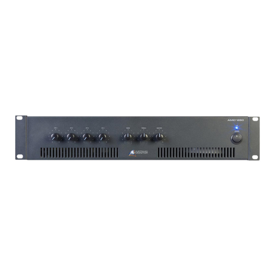
Page 5: Front Panel
FRONT PANEL CH 1–4 These control the levels for each channel input. Bass There is 12dB of cut and boost at 100Hz. Treble There is 9dB of cut and boost at 10kHz. Master This controls the overall mixed output level. This LED indicates the unit is powered “on”. -
Page 6: Rear Panel
(LINE). 70V out is available on 115V models. 100V out is available on 230V/240V models. (Optional) Tone Module These terminals are for use with an optional tone module (not supplied). Use Australian Monitor ATC5488 module. Phantom Power 12V phantom power is available for condenser or electret microphones on the XLR input when this switch is pushed in. -
Page 7: Installation
INSTALLATION Mounting Direct Output When rack mounting, it is advisable to allow 1 rack space above and below the The output terminal strip accepts wire sizes from 16-22AWG amplifier. When multiple amplifiers are mounted in a rack, exhaust fans should (1.5mm2 –... -
Page 8: Troubleshooting And Block Diagram
120 AMC 250 only) Make sure the amplifier is well ventilated DC fuse(s) blown Refer product to local Australian Monitor dealer Remove signal (disconnect input) from channel 1 OR No sound from channels 2 and 3 Priority function is being used... -
Page 9: Functional Notes And Internal Adjustments
FUNCTIONAL NOTES AND INTERNAL ADjUSTMENTS PRIORITY Channel 1 will mute channels 2, 3 and 4. This will only occur when signal appears on channel 1, irrespective of the channel volume control. Priority can be disabled. (See below). The release time is approx. 3 secs and is NOT adjustable. The mute depth is approx. 40dB and is not adjustable. PAGE 8 SERIES INSTALLATION AND OPERATION MANUAL... -
Page 10: Dimensions
DIMENSIONS SERIES INSTALLATION AND OPERATION MANUAL PAGE 9... -
Page 11: Specifications
SPECIFICATIONS POWER OUTPUT (0.5%THD, 1kHZ) 120W 250W S/N RATIO > 75dBr > 75dBr > 80dBr >85dBr POWER BANDWIDTH (-3dB +1dB) 85Hz-15kHz 75Hz-15kHz 75Hz-15kHz 30Hz-20kHz FUSES MAINS (115V) 1.0A 3.15A 6.3A MAINS (230/240V) 0.5A 1.6A 3.15A 1.6A (x2) 10A (x2) OUTPUT REgULATION SIZE (WXHXD) 482 x 88 x 190mm 482 x 88 x 281mm... - Page 12 SPECIFICATIONS COMMON TO ALL MODELS THD (1kHz, -1dB) Better than 0.5% MIC INPUT SENSITIVITY 1mV @ 200ohm IMPEDANCE 1k3 ohm HEADROOM 77mV (37dB) AUX INPUT SENSITIVITY 0.5V+/@100kohm IMPEDANCE >200kohm HEADROOM > 15V (>30dB) TONE CONTROL BASS @ 100HZ +/- 12 dB TREBLE @ 10KHZ +/- 9 dB LINE OUT...
- Page 13 AUSTRALIA AND NEW ZEALAND www.australianmonitor.com.au SYDNEY MELBOURNE BRISBANE ADELAIDE PERTH AUCKLAND (SA & NT SALES) (NSW & ACT SALES) (VIC & TAS SALES) (QLD SALES) (WA SALES) (NZ SALES) 1 Clyde Street 22/277 42 Commercial Road 31 Walsh Street 3/11 Howe Street 9C Piermark Drive Silverwater Middleborough Road...
- Page 14 8 AMP HRC *under PCB BC546B +24V +24V CN2A CN2B 68E / 2W 2A HRC (150E/5W) X 2 BD 139 Mains 240 V IC5B 1458 BD139 KBPC15 LM393 6800u/63V 6800u/63V IC5A PRIM1 230V 24V S1 47/50 47/50 FAN CIRCUT Australian Monitor AMC+250...
- Page 15 1N4007 Dirven by balanced signal 100E 100E BIAS *under PCB 10AMP HRC C1815 4.7u/25 470n/100V poly TIP41C BD139 TIP35C TIP35C TIP35C TIP35C TIP35C THERMISTOR 10K 100V 680R 470R BC639 330K 0.39E/5W 0.39E/5W 0.39E/5W 0.39E/5W 0.39E/5W 220E 4Ohm CON6 220E 0.39E/5W 0.39E/5W 0.39E/5W 0.39E/5W...
- Page 16 100R 100R 180k 10pF IC1A LM833 C1815 TAPE OUT 1/2VCC 100P 47/25V 1/2VCC Signal OUT+ 1/2VCC +12V IC3B LM833 1200P 4.7u OUT- Signal Line OUT+ 1/2VCC Line OUT- TAPE OUT 47PF 100p Tone Module Input C1815 PRIORITY IC1B IC3A LM833 10/25 LM833 1/2VCC...
- Page 17 RCA3 RCA 2P TAPE OUT RCA1A RCA-4POLE 330K 330K 10/25 NP 470p 680R 10/25 NP AG(1/2 VCC) +VCC XLR1 CH 1 OUT XLR-FEMALE 680R 10/25 NP CH 2 OUT IC1B CH 3 OUT LM833 CH 4 OUT MIX OUT MIX OUT TAPE OUT 470p CON10...
- Page 18 +24V +24V OP CT2...
- Page 19 1/2 VCC OUT+ OUT- TAPE OUT PRIORITY SIG+ SIG- +VCC +VCC MUTE TONE OUT...
- Page 20 R28 R29 1/2 VCC OUT- OUT+ TAPE OUT R32 R33...
-
Page 21: Test Procedure
TEST PROCEDURE 5062-1 MODEL: AMC250 Rev A 6/10/06 Original Rev B 11/10/06 Changes Rev C 30/11/07 New format Rev D 27/11/08 Correct AC fuse value Outline 1. Physical checks 2. Set up amplifier for test 2.1. Fuse check 2.2. Connections 2.3. - Page 22 Test Procedure VISUAL INSPECTION STAGE Physical checks • All screws for tightness (esp. bridge rectifier and transistor bolts), referring to the torque setting of the manufacturing tools • Capacitors for polarity • Earth connection for good contact, using multimeter (XLR GND to AC earth) •...
- Page 23 Put a multimeter across an emitter resistor. (P/F) Slowly adjust the preset PR1 so that you get 4.5mVDC (+/-0.5mVDC) reading. Check Quiescent Voltage across all Emitter resistors. (P/F) The emitter resistor voltages shall be 4.5mVDC (+/-2.0mVDC). [Setup for next test] Initial AC Checks : 4.1.
-
Page 24: Phantom Power
4.4. Outputs Setup Signal generator = ~1mVAC adjusted for 31.6V out with pots max, 1kHz Signal in = Ch4 XLR Channel pots = max (CW) Bass/Treble = centre Master pot = max (CW) Output metering = 4ohm out Load = 4ohm Procedure Using a multimeter check the following: (P/F) - Page 25 FINAL TESTING REQUIREMENTS FOR FINAL TESTING: a) Neutrik b) Load 40ohm c) Multimeter d) Oscilloscope e) Microphone f) Variac Setup Signal generator = 1mVAC, 1kHz Signal in = Ch1 XLR Channel pot = min (CCW) Bass/Treble = centre Master pot = min (CW) Output metering = 100Vout Load = 40ohm Procedure...
- Page 26 Bass/Treble = centre Master pot = max (CW) Output metering = 100Vout Load = 40ohm Procedure Measure the 100V line output. (P/F) The output readings shall be 100VAC (+/- 5VAC). Repeat for all channels. Bandwidth Setup Signal generator = 0.5VAC, 1kHz Signal in = Ch4 RCA Channel pot = max (CW) Bass/Treble = centre...
- Page 27 Reset the bass pot to centre. Set the frequency to 10kHz. Set the treble pot to max (CW). (P/F) The output reading shall be between 42VAC-50VAC. Set the treble pot to min (CCW). (P/F) The output reading shall be between 4VAC-6VAC. [Setup for next test] Reset the treble pot to centre.
-
Page 28: Current Limit
11. Current Limit Setup Signal generator = 0.5VAC, 1kHz Signal in = Ch4 RCA Ch pots = max (CW) Bass/Treble = centre Master pot = min (CCW) Output metering = 100Vout Load = 40ohm Procedure Change the load to 20ohms. Increase the signal such that at ~65VAC you can see the overload protection coming on with a rounding of the sine wave. - Page 29 (P/F) the fan shall switch on between 50degC - 70degC. Stall the fan and wait for the unit to heat some more. (P/F) The output shall mute to < 10V at a temp between 90–105degC Values to be recorded Value Pass Range 13a.
- Page 30 LISTENING TEST REQUIREMENTS FOR LISTENING TEST SETUP: a) CD Player b) Speaker c) Microphone 16. Listening Test Connect amplifier to the setup Keep all pots full, tone at center. 16.1. Switch on thump Switch on the set and check for any ON Thump. Ensure unit does not thump. Check that no low frequencies are audible.
- Page 31 Pass/Fail Summary Physical checks Set up amplifier for test : 2.1. Fuse check 2.2. Connections 2.3. Reset controls: Power up : (P/F) Current shall not exceed 0.5Aac. 3.1. Voltages (P/F) Pass Range DC power supply 47.5VDC - 50.5VDC Input PCB rail (p8) 11.0VDC –...
- Page 32 (P/F) The output shall return to 100VAC +/-10VAC in <10sec (Mental count is acceptable) while you are still speaking. 11. Current Limit (P/F) The mains current shall be < 3.5Aac. (P/F) The output shall be reading 30VAC +/-1V. 12. Noise floor / SNR (P/F) The output shall be reading <...
- Page 33 AMC+30 output board AMC+30OPB B03048 AMC+60 output board AMC+60OPB B06047 AMC120+ mixer board AMC+120MB B06044 AMC+120 output board AMC+120OPB B012046 AMC+250 output board AMC+250OPB BR025001 Transformers AMC+30 mains transformer AMC+30TX BR030123 AMC+30 output transformer AMC+30OT BR030124 AMC+60 mains transformer AMC+60TX...
- Page 34 Service Bulletin AMC+250 Mixer Amplifier AMC+250P Booster Amplifier 11 May 2011 Outline The AMC+250 mixer amplifier and AMC+250P booster amplifier have experienced a higher than acceptable incidences of mains fuse failures at turn on. Known Issue Mains fuse failure. Details The cause of the issue has been identified as the mains fuse used in production being of a rating that is too low for use in areas that encounter elevated mains voltages.
-
Page 35: Service Bulletin
Mains Fuses 20 February 2012 Applicable Models This bulletin applies to AMC+30, AMC+60, AMC+120 and AMC+250 Mixer Amplifiers and the AMC+120P, AMC+1202P and AMC+250P Booster Amplifiers manufactured prior to 2012. Known Issue The AMC+ range of mixer amplifiers and AMC+ booster amplifier have experienced a higher than acceptable incidences of mains fuse failures at turn on. - Page 36 AMC+250P Booster Amplifier 9 March 2012 Applicable Models This bulletin applies to AMC+250 and AMC+250P models manufactured prior to March 2012. For Information Only This bulletin is intended for service technicians only and is to be applied when replacing failed bridge rectifiers.
Need help?
Do you have a question about the AMC+250 and is the answer not in the manual?
Questions and answers