Table of Contents
Advertisement
Advertisement
Chapters
Table of Contents

Subscribe to Our Youtube Channel
Related Manuals for Hypertherm POWERMAX 800


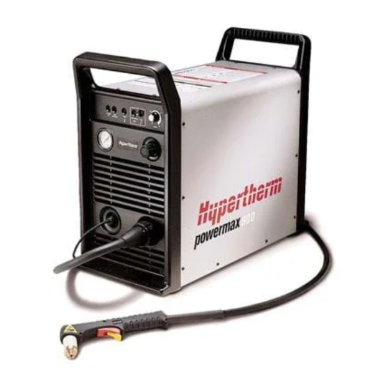
Summary of Contents for Hypertherm POWERMAX 800
- Page 1 ® Plasma Arc Cutting System Operator Manual 802270 Revision 5 EN50199 EN50192...
- Page 2 Hypertherm, Inc. P.O. Box 5010 Hanover, New Hampshire 03755-5010 Tel.: 603 643-3441 Fax: 603 643-5352 © Copyright Hypertherm, Inc. All Rights Reserved HYPERTHERM and POWERMAX are trademarks of Hypertherm, Inc. and may be registered in the United States and/or other countries.
- Page 3 Hypertherm Offices Worldwide : Hypertherm, Inc. Etna Road, P.O. Box 5010 Hanover, NH 03755 USA Tel.: (603) 643-3441 (Main Office) Fax: (603) 643-5352 (All Departments) Tel.: (800) 643-9878 (Technical Service) Tel.: (800) 737-2978 (Customer Service) Hypertherm Plasmatechnik GmbH Technologiepark Hanau Rodenbacher Chaussee 6 D–63457 Hanau-Wolfgang, Germany...
-
Page 4: Electromagnetic Compatibility
LECTROMAGNETIC OMPATIBILITY EMC INTRODUCTION e. Health of the people around, for Cutting Cables example the use of pacemakers and The cutting cables should be kept as The 400V CE power supply has been built hearing aids. short as possible and should be in compliance with standard EN50199. -
Page 5: Warranty
Torch, for which the warranty period shall be one (1) year, from the date of its delivery to you. HYPERTHERM, at its sole option, shall repair, replace, or adjust, free of charge, any Products covered by this warranty which shall be returned with HYPERTHERM's prior authorization (which shall not be... -
Page 6: Table Of Contents
ABLE OF ONTENTS ELECTROMAGNETIC COMPATIBILITY ....................i WARRANTY ............................ii SECTION 1 SAFETY ........................1-1 About Notes, Cautions & Warnings ....................1-1 Safety Instructions ..........................1-2 Eye Protection ..........................1-2 Skin Protection ..........................1-2 Toxic Fume Protection ........................1-2 Fire Prevention ..........................1-2 Electric Shock Prevention ...................... - Page 7 ABLE OF ONTENTS Work Cable and Clamp ........................3-10 Gas Supply Requirements ....................... 3-10 Gas Supply Connection ........................3-11 Torch Lead Connection ........................3-12 Machine Interface with PAC121MS ....................3-13 SECTION 4 OPERATION ......................4-1 Controls and Indicators ........................4-2 Operating Instructions ........................
-
Page 8: Table Of Contents
ABLE OF ONTENTS Figure 3-10C Three-Phase Power Configuration - 400V CE ............3-8 Figure 3-11 Proper Work Clamp Connection ................3-10 Figure 3-12 Recommended Three-Stage Air Filtration System ........... 3-11 Figure 3-13 Rear Panel, Gas Supply Connection to Filter ............3-11 Figure 3-14 ON/OFF Pendant Connection .................. -
Page 9: Section 1 Safety
Be aware of anything touching the workpiece. The workpiece is part this hazard, which has potential for of the electrical circuit. serious bodily injury. HYPERTHERM Plasma Systems 10/24/96... -
Page 10: Eye Protection
– Install protective screens or curtains to reduce ultraviolet transmission. Electric Shock Prevention All Hypertherm plasma systems use high Skin Protection voltage (up to 280 VDC) to initiate the plasma arc. Take the following precautions when • Wear protective clothing to protect against burns... -
Page 11: Explosion Prevention
(CSA) or applicable national or local codes. • Examine hoses at regular intervals for leaks, wear, loose connections or other hazard. • Never use a cylinder that leaks or is physically • Replace hose that is damaged in any way. damaged. HYPERTHERM Plasma Systems 10/24/96... -
Page 12: Noise Protection
• Coil any excess hose and place it out of the way to the retaining cap is loosened. prevent damage and to eliminate the danger of • Each Hypertherm plasma system is designed to be tripping. used only with specific Hypertherm torches. Do not... -
Page 13: Section 1A Sécurité
Se référer à l’annexe du manuel pour plus de • Ne pas couper de récipients contenant des matières renseignements sur les collecteurs d’aération. combustibles. HYPERTHERM Systèmes plasma 1a-1 10/6/98... - Page 14 • Installer un sectionneur avec fusibles appropriés, à la prise de terre appropriée. proximité de la source de courant. Ce dispositif permet à • Chaque système plasma Hypertherm est conçu pour être l’opérateur d’arrêter rapidement la source de courant en utilisé uniquement avec des torches Hypertherm cas d’urgence.
-
Page 15: Mise À La Masse Et À La Terre
Bien serrer l’écrou de retenue. Table de travail Raccorder la table de travail à la terre, • S’assurer que toutes les connexions sont bien serrées conformément aux codes de sécurité locaux ou nationaux pour éviter la surchauffe. appropriés. HYPERTHERM Systèmes plasma 1a-3 4/9/99 10/6/98... - Page 16 • Faire passer le faisceau de la torche le plus près possible du câble de retour. • Ne pas s’enrouler le faisceau de la torche ou le câble de retour autour du corps. • Se tenir le plus loin possible de la source de courant. 1a-4 HYPERTHERM Systèmes plasma 10/6/98 10/16/98...
-
Page 17: Description & Specifications
& S ESCRIPTION PECIFICATIONS Section 2 DESCRIPTION & SPECIFICATIONS In this section: Introduction ...................... 2-2 Specifications ....................2-3 Power Supply ....................2-3 PAC121 50A Torches ..................2-4 PAC121TS Hand Torch Assembly ............... 2-4 PAC121MS Machine Torch Assembly ............2-4 S Mark ......................2-5 IEC Symbols Used ................... -
Page 18: Introduction
& S ESCRIPTION PECIFICATIONS INTRODUCTION The Powermax800 plasma cutting system uses an inverter power supply to provide a smooth DC output voltage, producing excellent cut and gouge quality on mild steel, stainless steel, aluminum and other metals. The Powermax800 power supply provides constant-current output variable from 20 to 50 amps, for optimum performance on all thicknesses of metal up to 1/2 inch (12 mm) thick. -
Page 19: Specifications
& S ESCRIPTION PECIFICATIONS SPECIFICATIONS Power Supply Rated Open Circuit Voltage (OCV) (U ) ....300 VDC Rated Output Current (I ) ........20–50 amps Rated Output Voltage (U ) ........120 VDC Duty Cycle (X) @ 40°C......... 50% (I =50A, U =120V) 100% (I... -
Page 20: Pac121 50A Torches
& S ESCRIPTION PECIFICATIONS Weight ..............65 pounds (30 kg) without wheels 72 pounds (33 kg) with wheels 128 pounds (58 kg) for 600V power supply Gas Type .............. Air or Nitrogen Gas Quality, Air ............ Clean, dry, oil-free Gas Quality, Nitrogen ........... 99.995% pure Gas Inlet Pressure .......... -
Page 21: Smark
& S ESCRIPTION PECIFICATIONS MARK The Powermax800 conforms to standard EN50192. The S mark indicates that the power supply and torch are suitable for use in environments with increased hazard of electrical shock. The torches must have shielded consumable parts to maintain S mark compliance. See warning below and Figure 2-5. -
Page 22: Iec Symbols Used
& S ESCRIPTION PECIFICATIONS IEC SYMBOLS USED Direct Current (DC) Alternating current (AC) Plasma cutting torch AC input power connection The terminal for the external protective (earth) conductor An inverter-based power source Anode (+) work clamp Temperature switch Pressure switch Plasma torch in the TEST position (cooling and cutting gas exiting nozzle) Power is on Power is off... -
Page 23: Setup
ETUP Section 3 SETUP In this section: Upon Receipt ....................3-2 Claims ....................... 3-2 Hoisting Requirements ..................3-3 208/240/480 Voltage Configurations..............3-4 200/230/400 Voltage Configurations..............3-5 Power Cord Plugs ..................... 3-6 Single-Phase and Three-Phase Power Cords - 208/240/480V, Three-Phase Power Cords - 600V..............3-6 Single-Phase and Three-Phase Power Cords - 200/230/400V ...... -
Page 24: Upon Receipt
Claims for damage during shipment — If your unit was damaged during shipment, you must file a claim with the carrier. Hypertherm will furnish you with a copy of the bill of lading upon request. If you need additional assistance, call Customer Service at 1 800 643 0030 in the U.S. and Canada, or your authorized Hypertherm distributor. -
Page 25: Hoisting Requirements
ETUP HOISTING REQUIREMENTS In the event that the power supply has to be hoisted, read the Warning first and then perform the follow- ing procedure. See Fig. 3-1: WARNING The Powermax800 power supply weighs up to 72 pounds (33 kg) alone, 79 pounds (36 kg) with the torch and up to 135 pounds (61 kg) for the 600V unit with torch. -
Page 26: 208/240/480 Voltage Configurations
ETUP 208/240/480 VOLTAGE CONFIGURATIONS WARNING SHOCK HAZARD: Always turn off power, unplug cord from wall and wait 5 minutes before removing any power supply cover. If power supply is directly connected to a line disconnect switch, place line disconnect switch to OFF position. In the U.S., use a "lock-out / tag-out" procedure until the service or maintenance work is complete. -
Page 27: 200/230/400 Voltage Configurations
ETUP 200/230/400 VOLTAGE CONFIGURATIONS WARNING SHOCK HAZARD: Always turn off power, unplug cord from wall and wait 5 minutes before removing any power supply cover. If power supply is directly connected to a line disconnect switch, place line disconnect switch to OFF position. In the U.S., use a "lock-out / tag-out" procedure until the service or maintenance work is complete. -
Page 28: Power Cord Plugs
ETUP POWER CORD PLUGS All 208/240/480V power supplies are shipped with a single-phase power cord and plug. To operate as a three-phase unit, the user must obtain a power cord and plug that is certified by national or local electrical codes. The plug should be connected to the power cord by a licensed electrician. (See also Single-Phase and Three-Phase Power Cords - 208/240/480V later in this section.) All 200/230/400V and 400V CE power supplies are shipped with a three-phase power cord and no plug. -
Page 29: Single-Phase And Three-Phase Power Configurations
ETUP SINGLE-PHASE AND THREE-PHASE POWER CONFIGURATIONS All 208/240/480V Powermax800 power supplies are shipped for single-phase operation. All 200/230/400V Powermax800 power supplies are shipped for three-phase operation. However, all Powermax800 power supplies except the 400V CE and 600V power supplies can operate from either a single-phase or three-phase input. -
Page 30: Three-Phase 208/240/480V And 600V
ETUP Three-Phase 208/240/480V and 600V Remove the rear panel (Fig. 3-2) and connect the power cable to terminal block TB1 as shown in Fig. 3-10A. Connect the ground wire to the stud marked above the terminal block. . Conductor Color Ground Green Figure 3-10A... -
Page 31: Power Requirements
ETUP POWER REQUIREMENTS Line Voltage Disconnect Box Use a line disconnect box for each power supply. This disconnect box allows the operator to turn the power supply off quickly in an emergency situation. The switch should be located on a wall near the power supply, and should be easily accessible to the operator. -
Page 32: Work Cable And Clamp
ETUP Figure 3-11 Proper Work Clamp Connection WORK CABLE AND CLAMP The work clamp must be attached to the workpiece to perform plasma cutting. Ensure that the work clamp and the workpiece make good metal-to-metal contact. Attach the work clamp as close as pos- sible to the area being cut to reduce exposure to electric and magnetic fields (EMF). -
Page 33: Gas Supply Connection
ETUP Additional Air Filtration Use a three-stage coalescing filtration system as shown in Fig. 3-12 when site conditions introduce moisture, oil or other contaminants into the air line. Water/particle filter Oil filter Oil vapor filter From air supply Powermax800 Figure 3-12 Recommended Three-Stage Air Filtration System Nitrogen Supply Nitrogen must be supplied to the Powermax800 at 99.995% purity. -
Page 34: Torch Lead Connection
ETUP TORCH LEAD CONNECTION To connect the torch lead to the power supply: 1. Align the connector key plug (on torch lead) with the connector receptacle key slot (on power supply) and push in until pins seat. 2. Turn the connector securing ring 1/4 turn to the left to ensure that the securing ring threads and the connector receptacle threads are aligned prior to tightening. -
Page 35: Machine Interface With Pac121Ms
ETUP PAC121MS Torch Alignment Make sure that the machine torch is mounted at right angles to the workpiece in order to get a vertical cut. Use a square to align the torch at 0° and 90° as shown in Fig. 3-15. Torch - (typ.) 0°... -
Page 36: Arc Voltage
ETUP Arc Voltage If arc voltage is necessary for activating a torch height control, the customer must supply an 18AWG, single pair, unshielded cable rated for 300V or greater. The arc voltage signal on the machine interface board can be accessed as follows: WARNING SHOCK HAZARD: Always turn off power, unplug cord from wall and wait 5 minutes before removing any power supply cover. -
Page 37: Operation
PERATION Section 4 OPERATION In this section: Controls and Indicators ................... 4-2 Operating Instructions ..................4-3 Pilot Arc Controller Option ................4-4 PAC121TS Safety Trigger Operation ............4-5 Operating Tips ....................4-6 Changing Consumable Parts..............4-6 Cutting ......................4-8 Piercing..................... 4-10 Gouging .....................4-11 Cut Chart - 50A Standard Consumables ............ -
Page 38: Controls And Indicators
PERATION CONTROLS AND INDICATORS • Green POWER ON LED When illuminated, indicates that all control circuits are activated, the torch safety interlock is satisfied and the system is ready for operation. • Yellow LINE VOLTAGE LED When illuminated, indicates that the AC line voltage is above or below proper operating limits. •... -
Page 39: Operating Instructions
PERATION OPERATING INSTRUCTIONS WARNING Before operating this system, read the Safety section of this manual thoroughly! 1. Ensure that the work environment and your clothing meet the safety requirements outlined in the Safety section. 2. Follow the instructions in the Setup section. Verify that the input gas supply pressure is set to 90 psi (6.2 bar). -
Page 40: Pilot Arc Controller Option
PERATION 6. Attach the work clamp securely to the workpiece. Do not attach it to the portion that will fall away. Figure 4-3 Proper Work Clamp Connection WARNING The PAC121 torches are instant-on torches. These torches produce a plasma arc immediately after the torch start switch closes. -
Page 41: Pac121Ts Safety Trigger Operation
PERATION PAC121TS Safety Trigger Operation The PAC121TS safety trigger torch allows operators to safely handle the torch before and after the cut and to minimize the possibility of accidental torch firing. The safety trigger is easy to operate. Follow the steps below. Safety On position. -
Page 42: Operating Tips
PERATION OPERATING TIPS Changing Consumable Parts WARNING SHOCK HAZARD: Always turn off power and unplug cord from wall before changing consumable parts. If power supply is directly connected to a line disconnect switch, place line disconnect switch to OFF position. Do not rely on the cap-on sensor switch to remove power. It is provided strictly for safety backup. -
Page 43: Figure 4-5A Consumables
PERATION Shields 120601 Nozzles Retaining Cap 120282 120301 Shielded 120602 Figure 4-5A Consumables 120438 Deflector 120301 120303 020395 Swirl Electrodes Ring PAC121 Non-Shielded 120573 (Air) Torch 020480 (N 020361 Gouging Shield 120301 120608 120281 O-Ring Gouging 044016 120304 Deflector 120301 120574 120303 120305... -
Page 44: Cutting
PERATION Cutting • Do not fire the pilot arc into the air needlessly—doing so causes a significant reduction of the nozzle and electrode life. • If arc transfer to the workpiece does not occur within 5 seconds, the pilot arc will shut off. Re- lease the torch start switch and press it again to reset the pilot arc timer. -
Page 45: Figure 4-7 Cutting A Circle
PERATION Figure 4-7 Cutting a Circle Figure 4-8 Dragging the Torch Operator Manual... -
Page 46: Piercing
PERATION Piercing • Hold the torch so that the nozzle is approximately 1/16 inch (1.6 mm) away from the workpiece before firing the torch. This method maximizes the life of the nozzle. • Hold the torch at an angle to the workpiece away from yourself, then slowly rotate it to an upright position. -
Page 47: Gouging
PERATION Gouging The Powermax800 can be used for gouging mild steel by using the optional gouging nozzle and gouging shield. To gouge: • Always wear full protection: - A welding helmet with at least a #8 lens shade - Welding gloves - A welding jacket The arc is fully exposed and will cause serious burns if the skin is not covered. -
Page 48: Cut Chart - 50A Standard Consumables
PERATION CUT CHART - 50A STANDARD CONSUMABLES The following recommended settings are for mechanized cutting at 50 amps. Torch-to-work distance for the following cut charts is 1/16 inch (1.6 mm) for all cuts. Swirl Ring Retaining Cap Nozzle PAC121 Shield Electrode 020361 120282... -
Page 49: Cut Chart - 40A Consumables
PERATION CUT CHART - 40A CONSUMABLES Use 40 amp consumables on thin material to obtain a narrow kerf width and to minimize the heat- affected zone. The following recommended settings are for mechanized cutting. Torch-to-work distance is 1/16 inch (1.6 mm) for all cuts. Swirl Ring Retaining Cap... -
Page 50: Common Cutting Faults
PERATION Cut Chart Notes (continued): • Maximum recommended mechanized cutting capacity: 3/8 inch (10 mm). • See page 4-7 or Section 5 for additional consumable parts. • Compressed air or nitrogen must be available to the power supply filter/pressure regulator at a flow rate of 320 scfh/5.3 scfm (150 l/min) at a pressure of 90 psi (6.2 bar). -
Page 51: Maintenance/Parts
AINTENANCE ARTS Section 5 MAINTENANCE/PARTS In this section: Introduction ..................... 5-2 Routine Maintenance ..................5-2 Bowl Draining and Filter Element Cleaning ..........5-2 Cooling Air Filter Removal, Cleaning and Replacement......5-3 PAC121TS Torch Parts Removal and Replacement ........5-4 Torch Main Body Removal and Replacement ..........5-4 Torch Switch Removal and Replacement ........... -
Page 52: Introduction
AINTENANCE ARTS INTRODUCTION This section contains information for simple maintenance and troubleshooting. A brief parts list is also included. For higher level troubleshooting, see Technical Questions later in this section. ROUTINE MAINTENANCE Bowl Draining and Filter Element Cleaning Moisture coming out of the torch can cause the torch to sputter and hiss. If there is moisture, purge the lines. -
Page 53: Cooling Air Filter Removal, Cleaning And Replacement
AINTENANCE ARTS Cooling Air Filter Removal, Cleaning and Replacement Powermax800 systems are normally shipped without air filters. If your Powermax800 has the air filter option, it will need cleaning periodically. Excessively dirty or dusty environments can block the cooling air filter (if installed) and cause the power supply to overheat and shut down. WARNING SHOCK HAZARD: Always turn off power, unplug cord from wall and wait 5 minutes before removing any power supply cover. -
Page 54: Pac121Ts Torch Parts Removal And Replacement
AINTENANCE ARTS PAC121TS TORCH PARTS REMOVAL AND REPLACEMENT Torch Main Body Removal and Replacement To remove and replace the torch main body, order the torch main body with cap-on sensor switch and refer to the following procedure and Figures 5-3 and 5-4. Set the Powermax800 power switch to O (off), unplug the power cable, and disconnect the gas supply. -
Page 55: Torch Switch Removal And Replacement
AINTENANCE ARTS Torch Switch Removal and Replacement To remove and replace the torch switch, order the torch switch and two splices (074069) and refer to the following procedure and Fig. 5-4. See Parts later in this section for a complete list of torch parts. 1. -
Page 56: Pac121Ms Torch Parts Removal And Replacement
AINTENANCE ARTS PAC121MS TORCH PARTS REMOVAL AND REPLACEMENT Repair of the PAC121MS machine torch normally requires replacement of the torch main body and/or the torch lead. Order the torch main body. Refer to Fig. 5-5 and perform the steps below. See Parts later in this section for a complete list of torch parts. -
Page 57: Parts
AINTENANCE ARTS Torch Cap Sensor Screw Main Body Microswitch Wires (2) White Blue Torch Position Shield O-Ring Screw (3) Wires (2) Wires (2) Torch Lead Sleeve Black Plunger White Wires Torch Retaining Wires (2) Sleeve (4 ea.) Figure 5-5 PAC121MS Torch Assembly 6. -
Page 58: Basic Troubleshooting
AINTENANCE ARTS BASIC TROUBLESHOOTING LINE TEMP PRESSURE ON/OFF VOLTAGE Power Switch POWER Cause / Solution Problem 1. The ON/OFF power switch is set to I (ON), 1.1 The power cord is not plugged into the but the fan does not operate and the POWER power receptacle. - Page 59 AINTENANCE ARTS Cause / Solution Problem Note: To avoid performance deterioration of the Powermax800, input voltage should be within 10% of the specified system line voltage setting. System Lower Limit Line Voltage Upper Limit 170VAC 200VAC 235VAC 178VAC 208VAC 239VAC 195VAC 230VAC 270VAC...
-
Page 60: Technical Questions
If you are unable to fix the problem with your Powermax800 by following this basic troubleshooting guide or if you need further assistance: 1. Call your distributor. He/she will be able to help you, or refer you to an authorized Hypertherm repair facility. -
Page 61: Parts
AINTENANCE ARTS PARTS WARNING Consumable Parts For CE compliance in hand torch applications, Shields shielded consumable parts must be used. 120601 See page 5-12 for a complete list. Retaining Cap 120301 Nozzles 120282 Shielded 120602 Figure 5-6A Consumable Parts 120438 Deflector 120301 120303... -
Page 62: Consumable Parts - For Ce Compliance
AINTENANCE ARTS Consumable Parts - For CE Compliance Note: See page 5-11 for a list of in Hand Torch Applications consumable parts for non-CE countries. Shields 120601 Retaining Cap 120301 Nozzles 120282 Shielded 120602 Swirl Electrode Ring PAC121 120573 Torch 020361 O-Ring Gouging Shield... -
Page 63: Pac121Ts Torch Assembly
AINTENANCE ARTS PAC121TS Torch Assembly and 25 ft (7.6 m) Lead - 083003 PAC121TS Torch Assembly and 50 ft (15.2 m) Lead - 083004 Part Number Description 001288 ......... Handle, PAC121T 002244 ......... Safety Trigger, PAC121T 005094 ......... Switch, Torch Pushbutton 020351 ......... -
Page 64: Pac121Ms Torch Assembly
AINTENANCE ARTS PAC121MS Torch Assembly and 14 ft (4.3 m) Lead - 083049 w/pigtail, 083054 no pigtail PAC121MS Torch Assembly and 25 ft (7.6 m) Lead - 083011 w/pigtail, 083056 no pigtail PAC121MS Torch Assembly and 35 ft (10.6 m) Lead - 083044 w/pigtail, 083057 no pigtail PAC121MS Torch Assembly and 50 ft (15.2 m) Lead - 083012 w/pigtail, 083058 no pigtail Part Number Description... -
Page 65: Power Supplies - 208/240/480V
Part With Pilot Arc With Machine Number Torch Type Control Interface 083030 Hand 083033 Hand 083036 Machine 083039 Machine Note: Contact your distributor or call the nearest Hypertherm office for hand and machine torch system configurations. 5-15 Operator Manual 9-96... -
Page 66: Power Supplies - 400V Ce
Part With Pilot Arc With Machine Number Torch Type Control Interface 083018 Hand 083021 Hand 083024 Machine 083027 Machine Note: Contact your distributor or call the nearest Hypertherm office for hand and machine torch system configurations. 5-16 Operator Manual 9-96... -
Page 67: Figure A-1 F1 And F2 Fuse Location
HANGING USES PPENDIX In the event that the Powermax800 was configured incorrectly for the incoming power, fuses F1 and/or F2 may have blown to protect the power supply. WARNING SHOCK HAZARD: Always turn off power, unplug cord from wall and wait 5 minutes before removing any power supply cover. - Page 68 PPENDIX TANDARDS NDEX STANDARDS INDEX The Standards Index contains a list of publications dealing with plasma arc cutting equipment safety practices. ANSI Standard Z49.1, Safety in Welding and Cutting , obtainable from the American Welding Society, 550 LeJeune Road, P.O. Box 351020, Miami, FL 33135. NIOSH, Safety and Health in Arc Welding and Gas Welding and Cutting , obtainable from the Superintendent of Documents, U.S.
-
Page 69: Figure C-1 Aeration Manifold
HANGING USES PPENDIX ERATION ANIFOLD PPENDIX AERATION MANIFOLD FOR PLASMA CUTTING ALUMINUM Introduction When plasma arc cutting aluminum at the water table surface or below water, free hydrogen gas may be generated by the cutting process. The high temperature of the plasma process causes disassociation of oxygen and hydrogen from the water in the water table.
Need help?
Do you have a question about the POWERMAX 800 and is the answer not in the manual?
Questions and answers