Advertisement
Advertisement
Chapters
Troubleshooting

Related Manuals for Hypertherm powermax 190c


Summary of Contents for Hypertherm powermax 190c
- Page 1 ® Plasma Arc Cutting System Service Manual 803660 Revision 4...
- Page 2 (P/N 803660) Revision 4 – June, 2005 Hypertherm, Inc. Hanover, NH USA www.hypertherm.com © Copyright 2005 Hypertherm, Inc. All Rights Reserved Hypertherm and Powermax are trademarks of Hypertherm, Inc. and may be registered in the United States and/or other countries.
- Page 3 Rua Jati, 33 65 6 841 2489 (Technical Service) CEP 07180-350 Cumbica Guarulhos, SP - Brasil Hypertherm (Shanghai) Consulting Co., Ltd. 55 11 6482 1087 Tel Unit 1308-09, Careri Building 55 11 6482 0591 Fax 432 West Huai Hai Road...
- Page 4 The size of the surrounding area to be Earthing of Workpiece considered will depend on the structure of Hypertherm's CE-marked equipment is built Where the workpiece is not bonded to earth the building and other activities that are tak- in compliance with standard EN50199. The for electrical safety, nor connected to earth ing place.
-
Page 5: Warranty
Hypertherm system. Any damage infringement, and Hypertherm’s obligation to indemnify shall be caused by the use of other than genuine Hypertherm parts may conditioned upon Hypertherm’s sole control of, and the not be covered by the Hypertherm warranty. -
Page 6: Table Of Contents
TABLE OF CONTENTS Electromagnetic Compatibility ..........................i Warranty..................................ii Section 1 SAFETY..............................1-1 Recognize Safety Information...........................1-2 Follow Safety Instructions ............................1-2 Cutting Can Cause Fire or Explosion ........................1-2 Electric Shock Can Kill..............................1-3 Cutting Can Produce Toxic Fumes ...........................1-3 A Plasma Arc Can Cause Injury and Burns ......................1-4 Arc Rays Can Burn Eyes and Skin ...........................1-4 Grounding Safety ..............................1-4 Compressed Gas Equipment Safety ........................1-5... - Page 7 TABLE OF CONTENTS Section 2 SPECIFICATIONS ..........................2-1 Introduction ................................2-2 Specifications................................2-2 Power Supply ..............................2-2 PAC105 Torch..............................2-3 IEC Symbols Used..............................2-4 Grounding Requirements............................2-5 Power Cord Plugs ..............................2-5 Power Hookup ................................2-6 System Circuit Recommendations ........................2-6 Extension Cord Recommendations........................2-6 Section 3 MAINTENANCE ...........................3-1 Introduction ................................3-2 Routine Maintenance ..............................3-2 Before Each Use ..............................3-2 Every Week ................................3-2...
-
Page 8: Safety
Compressed Gas Equipment Safety ........................1-5 Gas Cylinders Can Explode If Damaged ........................1-5 Noise Can Damage Hearing .............................1-5 Pacemaker and Hearing Aid Operation ........................1-5 A Plasma Arc Can Damage Frozen Pipes ........................1-5 Additional Safety Information ............................1-5 Warning Label................................1-6 Hypertherm Plasma Systems... -
Page 9: Recognize Safety Information
• Install an aeration manifold on the floor of the water closed container. table to eliminate the possibility of hydrogen • Do not cut containers that have held combustible detonation. Refer to the Appendix section of this materials. manual for aeration manifold details. Hypertherm Plasma Systems 11-98... -
Page 10: Electric Shock Can Kill
• Provide a disconnect switch close to the power grounding conductor first. supply with properly sized fuses. This switch allows • Each Hypertherm plasma system is designed to be the operator to turn off the power supply quickly in used only with specific Hypertherm torches. Do not an emergency situation. -
Page 11: A Plasma Arc Can Cause Injury And Burns
Work Table Connect the work table to an earth power cord ground. Fasten the retaining nut tightly. ground, in accordance with appropriate national or • Tighten all electrical connections to avoid excessive local electrical codes. heating. Hypertherm Plasma Systems 5/6/02... -
Page 12: Compressed Gas Equipment Safety
Protection Association, 470 Atlantic Avenue, Boston, MA 02210 Hazardous Substances, American Welding Society 10. OSHA, Safety and Health Standards, 29FR 1910 550 LeJeune Road, P.O. Box 351040, Miami, FL 33135 U.S. Government Printing Office, Washington, D.C. 20402 Hypertherm Plasma Systems 11-98... -
Page 13: Warning Label
Become trained and read the instructions before 3.1 Wear insulating gloves. Do not wear wet or working on the machine or cutting. damaged gloves. Do not remove or paint over (cover) warning labels. 3.2 Insulate yourself from work and ground. Hypertherm Plasma Systems 8-99... -
Page 14: Section 1A
Les bouteilles de gaz comprimé peuvent exploser en cas de dommages .............1a-5 Le bruit peut provoquer des problèmes auditifs......................1a-5 Pacemakers et prothèses auditives ........................1a-5 Un arc plasma peut endommager les tuyaux gelés....................1a-5 Étiquette de sécurité ...............................1a-6 Hypertherm Systèmes plasma 1a-1 2/12/01... -
Page 15: Identifier Les Consignes De Sécurité
• Ne pas couper de récipients contenant des matières Se référer à l’annexe du manuel pour plus de combustibles. renseignements sur les collecteurs d’aération. 1a-2 Hypertherm Systèmes plasma 2/12/01... -
Page 16: Les Chocs Électriques Peuvent Être Fatals
• Installer un sectionneur avec fusibles appropriés, à la prise de terre appropriée. proximité de la source de courant. Ce dispositif permet à • Chaque système plasma Hypertherm est conçu pour être l’opérateur d’arrêter rapidement la source de courant en utilisé uniquement avec des torches Hypertherm cas d’urgence. -
Page 17: L'arc Plasma Peut Provoquer Des Blessures Ou Des Brûlures
Bien serrer l’écrou de retenue. Table de travail Raccorder la table de travail à la terre, • S’assurer que toutes les connexions sont bien serrées conformément aux codes de sécurité locaux ou nationaux pour éviter la surchauffe. appropriés. 1a-4 Hypertherm Systèmes plasma 5/6/02... -
Page 18: Sécurité Des Bouteilles De Gaz Comprimé
LES TUYAUX GELÉS • Se tenir le plus loin possible de la source de courant. Les tuyaux gelés peuvent être endommagés ou éclater si l'on essaie de les dégeler avec une torche plasma. Hypertherm Systèmes plasma 1a-5 2/12/01... -
Page 19: Étiquette De Sécurité
3.1 Porter des gants isolants. Ne pas porter de gants procéder au coupage. mouillés ou abîmés. 7. Ne pas retirer ou peindre (recouvrir) les étiquettes 3.2 S’isoler de la surface de travail et du sol. de sécurité. 1a-6 Hypertherm Systèmes plasma 2/12/01... -
Page 20: Specifications
Section 2 SPECIFICATIONS In this section: Introduction ................................2-2 Specifications................................2-2 Power Supply ..............................2-2 PAC105 Torch ..............................2-3 IEC Symbols Used..............................2-4 Grounding Requirements............................2-5 Power Cord Plugs ..............................2-5 Power Hookup ................................2-6 System Circuit Recommendations ........................2-6 Extension Cord Recommendations........................2-6 powermax190 Service Manual... -
Page 21: Introduction
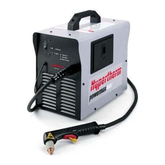
SPECIFICATIONS Introduction The Powermax190c plasma cutting system uses a chopper power supply to cut mild steel, stainless steel, aluminum and other metals. This service manual provides information for qualified service technicians to troubleshoot and repair the power supply and torch. Section 4 contains a parts list of the Powermax190c system. This manual also provides a detailed list of safety practices, so that the system can be safely tested and maintained. -
Page 22: Pac105 Torch
SPECIFICATIONS Power Cord Work Lead 15.8" (400 mm) 12" (305 mm) PAC105 Torch 8.5" (216 mm) PAC105 Torch Recommended Cutting Capacity......1/8 inch (3 mm) @ 12A (35% duty cycle) Maximum Cutting Capacity ........3/16 inch (4.5 mm) @ 12A (35% duty cycle) Severance Cutting Capacity ........1/4 inch (6 mm) @ 12A (35% duty cycle) Air Pressure and Flow rate ........40 psi (2.8 bar) @ 53.4 scfh/0.89 cfm (25 liters/min) - Page 23 SPECIFICATIONS S MARK The 230V Powermax190c system conforms to standard EN50192. The S mark indicates that the power supply and torch are suitable for use in environments with increased hazard of electrical shock. Direct current (DC). Alternating current (AC). Plasma cutting torch. AC input power connection.
-
Page 24: Grounding Requirements
SPECIFICATIONS Grounding Requirements To ensure personal safety, proper operation and to reduce electromagnetic interference (EMI), the power supply must be properly grounded: • The power supply must be grounded through the power cord according to national or local electrical codes. •... -
Page 25: Power Hookup
SPECIFICATIONS Power Hookup System Circuit Recommendations 120V power supply: An individual 30A branch circuit is recommended, protected by time-delay fuses or circuit breaker 230V power supply: An individual 20A branch circuit is recommended, protected by time-delay fuses or circuit breaker Work lead and clamp Power cord Plug power cord into a properly grounded... -
Page 26: Maintenance
Section 3 MAINTENANCE In this section: Introduction ................................3-2 Routine Maintenance ..............................3-2 Before Each Use ..............................3-2 Every Week ..............................3-2 3 Months ................................3-2 6 Months ................................3-2 Controls and Indicators ............................3-3 Theory of Operation ..............................3-4 Troubleshooting ................................3-5 Test Equipment ..............................3-5 Troubleshooting Procedures ..........................3-5 Visual Inspection –... -
Page 27: Introduction
MAINTENANCE Introduction Hypertherm assumes that the service personnel performing the troubleshooting testing are high-level electronic service technicians that have worked with high-voltage electromechanical systems. Knowledge of final isolation troubleshooting techniques is also assumed. In addition to being technically qualified, maintenance personnel must perform all testing with safety in mind. -
Page 28: Controls And Indicators
MAINTENANCE Controls and Indicators Power Switch POWER ON FAULT When illuminated, indicates that The fault lamp will illuminate the power supply is energized under the following conditions: and ready to operate. Lamp will extinguish if input power is not 1. The torch retaining cap is within specified range. -
Page 29: Theory Of Operation
MAINTENANCE Theory of Operation AC power enters the system through inrush resistor R1 into switch S1 then into the main transformer. The main transformer T1 supplies voltage to the control circuitry and to the chopper module. The inrush contactor CR2 is closed by the control circuitry on the power board PC1. -
Page 30: Troubleshooting
The complexity of the circuits require that service technicians have a working knowledge of chopper power supply theory. In addition to being technically qualified, technicians must perform all testing with safety in mind. If questions or problems arise during servicing, call the nearest Hypertherm Technical Services Department listed in the front of this manual. -
Page 31: Visual Inspection - Internal
Removal of the protective conformal coatings and other unauthorized repairs to the PC boards will void the warranty. If questions or problems arise during servicing, call the Hypertherm Technical Services department listed in the front of this manual. 1. Set the Powermax190c power switch to O (off) and unplug the power cord. -
Page 32: Powermax190C Troubleshooting Guide
Powermax190c Troubleshooting Guide Refer to Wiring Diagrams y f i e l l s t r f s i e l l . y l y t i , t i c t i y f i c t i c i l c t i y f i... - Page 33 Powermax190c Troubleshooting Guide l l i n i l n i l c t i y t l y t l t s i n i l y t l c t i n i l y t l y t l c t i c t i y t i...
- Page 34 Powermax190c Troubleshooting Guide r i f o t u o t u o t u o t u y f i y f i y t l ≥ t i l y t l y t l r i f y t l e i l e i l...
- Page 35 Powermax190c Troubleshooting Guide ) . t y t l y f i . y l y l t y f i l l a c t i y t l y f i Ω y f i l a i y f i...
-
Page 36: Parts List
Section 4 PARTS LIST In this section: Powermax190c 120V Power Supply – 070068 ......................4-2 Powermax190c 230V Power Supply – 070070 ......................4-3 PAC105 Torch Assembly and 20 ft (6.1 m) Torch Lead – 070065 ................4-4 Consumable O-rings ..............................4-5 Consumable Parts ..............................4-5 Powermax190c Labels .............................4-6 Optional Parts ................................4-6 Powermax190c Systems ............................4-6... -
Page 37: Powermax190C 120V Power Supply
PARTS LIST Powermax190c 120V Power Supply – 070068 Index No. Part No. Description Ref. Desig. Quantity 060136 Cover Assembly: Powermax190c 060006 Fan: Powermax190c 120/60 060076 Relay: Powermax190c/350 30A 12V SPST 060078 Thermistor: Powermax190c 060135 Relay: Powermax190c 060138 Linecord: Powermax190c 120V 060134 Shock Absorber: Powermax190c 060131... -
Page 38: Powermax190C 230V Power Supply
PARTS LIST Powermax190c 230V Power Supply – 070070 Index No. Part No. Description Ref. Desig. Quantity 060153 Cover Assembly: Powermax190c - 230V (CE) 060142 Fan: Powermax190c 230/50 060217 Relay: Powermax190c/350 30A 12V SPST 060078 Thermistor: Powermax190c 060135 Relay: Powermax190c 060145 Linecord: Powermax190c 230V 060134 Shock Absorber: Powermax190c... - Page 39 PARTS LIST Powermax190c 120V Power Supply – 070784 Index No. Part No. Description Ref. Desig. Quantity 060136 Cover Assembly: Powermax190c 060006 Fan: Powermax190c 120/60 060217 Relay: Powermax190c/350 30A 12V SPST 060078 Thermistor: Powermax190c 060135 Relay: Powermax190c 060138 Linecord: Powermax190c 120V 060134 Shock Absorber: Powermax190c 060215...
- Page 40 PCB Assy: Powermax190c 230V 060154 Thermostat:PMX190C-230V [CE] NC 195F 070065 PAC105 Hand Torch Assembly (See page 4-4) 060133 Cable with clamp: Powermax190c work 060151 Switch: Powermax190c On/Off, 230V, 2-pole 060143 Transformer: Powermax190c 230/1/50 060161 Inductor: Powermax 190c powermax190 Service Manual...
-
Page 41: Pac105 Torch Assembly And 20 Ft (6.1 M) Torch Lead - 070065
PARTS LIST PAC105 Torch Assembly and 20 ft (6.1 m) Torch Lead – 070065 Index No. Part No. Description 001288 Handle 027254 Spring 002244 Safety Trigger Assembly 120874 Torch Main Body with Switch, PAC105 058503 O-Ring: VITON .625 X .070 075339 Screws (5), P/S, # 4 X 1/2, PH, RND, S/B 128883... -
Page 42: Consumable O-Rings
PARTS LIST Consumable Parts Part Number Description 120880..............Swirl Ring 120881..............Electrode 120882..............Nozzle 120883..............Retaining Cap 120898..............Shielded Retaining Cap 120884..............Shield Electrode Shield Nozzle Swirl Ring Shielded Retaining Cap 120881 120884 120882 120880 120898 Shielded Consumables Electrode Nozzle Swirl Ring Retaining Cap 120881 120882 120880 120883 Unshielded Consumables... -
Page 43: Powermax190C Labels
PARTS LIST Powermax190c Labels 110253 110124 110291 110290 110459 110458 230V Data label 120V Data label 230V Data label 120V Data label for 070069 for 070067 for 070786 for 070784 Optional Parts Part Number Description 060133 Work lead with clamp 060138 Power cord, Pmx190c, 120V 060145... -
Page 44: Wiring Diagrams
Section 5 WIRING DIAGRAMS In this section: Powermax190c 120V Wiring Diagram ........................5-2 Powermax190c 230V Wiring Diagram ........................5-3 Powermax190c 120/230 VAC Wiring Diagram ......................5-4 powermax190 Service Manual 2-00... - Page 45 Voltage Readings WARNING a) Tolerance ± 10 % unless specified b) Reference - to circuit common, lead 43 unless noted SHOCK HAZARD: Always turn off the power and 120 VAC 24 VAC unplug the cord or set the line disconnect switch to 120 VAC 12 VDC Off before servicing the unit or changing consumable...
- Page 46 Voltage Readings WARNING a) Tolerance ± 10 % unless specified b) Reference - to circuit common, lead 43 unless noted SHOCK HAZARD: Always turn off the power and 230 VAC 24 VAC unplug the cord or set the line disconnect switch to 230 VAC 12 VDC Off before servicing the unit or changing consumable...
- Page 47 Voltage Readings WARNING a) Tolerance ± 10 % unless specified b) Reference - to circuit common, lead 43 unless noted SHOCK HAZARD: Always turn off the power and 120 VAC 24 VAC unplug the cord or set the line disconnect switch to 120 VAC 14 VDC Off before servicing the unit or changing consumable...
Need help?
Do you have a question about the powermax 190c and is the answer not in the manual?
Questions and answers