Hypertherm HyDefinition HD3070 Instruction Manual
Lasma arc cutting system with automatic gas console
Hide thumbs
Also See for HyDefinition HD3070:
- Product configuration manual (35 pages) ,
- Instruction manual (247 pages)

Related Manuals for Hypertherm HyDefinition HD3070


Summary of Contents for Hypertherm HyDefinition HD3070
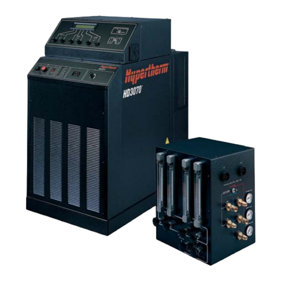
- Page 1 HyDefinition ® HD3070 ™ Plasma Arc Cutting System with Automatic Gas Console Instruction Manual 802180 – Revision 19 The world leader in plasma cutting technology...
- Page 2 Page of Change Description of Change Rev 17 to 18 7/25/02 iv, v, vi, vii, viii Updated Main Table of Contents to reflect changes below. Updated TOC Added page after 2-10 with torch art and dimensions for both the straight and 45 degree 2.10 &...
- Page 14 (P/N 802180) Revision 19 – November, 2013 Hypertherm, Inc. Hanover, NH USA www.hypertherm.com © Copyright 2013 Hypertherm, Inc. All Rights Reserved Hypertherm, HyDefinition and LongLife are trademarks of Hypertherm, Inc. and may be registered in the United States and/or other countries...
- Page 15 63457 Hanau-Wolfgang, Deutschland 49 6181 58 2100 Tel 49 6181 58 2134 Fax 49 6181 58 2123 (Technical Service) Hypertherm Singapore Pte Ltd No. 19 Kaki Bukit Road 2 K.B. Warehouse Complex Singapore 417847, Republic of Singapore 65 841 2489 Tel...
-
Page 16: Electromagnetic Compatibility (Emc
The size of the surrounding area to be Earthing of Workpiece considered will depend on the structure of Hypertherm's CE-marked equipment is built Where the workpiece is not bonded to earth the building and other activities that are tak- in compliance with standard EN50199. The for electrical safety, nor connected to earth ing place. -
Page 17: Warranty
Hypertherm system. Any damage infringement, and Hypertherm’s obligation to indemnify shall be caused by the use of other than genuine Hypertherm parts may conditioned upon Hypertherm’s sole control of, and the not be covered by the Hypertherm warranty. -
Page 18: Table Of Contents
TABLE OF CONTENTS Electromagnetic Compatibility (EMC) ........................i Warranty ..................................ii Section 1 SAFETY..............................1-1 Recognize Safety Information...........................1-2 Follow Safety Instructions ............................1-2 Cutting Can Cause Fire or Explosion ........................1-2 Electric Shock Can Kill..............................1-3 Cutting Can Produce Toxic Fumes ...........................1-3 A Plasma Arc Can Cause Injury and Burns ......................1-4 Arc Rays Can Burn Eyes and Skin ...........................1-4 Grounding Safety ..............................1-4 Compressed Gas Equipment Safety ........................1-5... - Page 19 TABLE OF CONTENTS Optional Units..............................2-4 Timer-Counter ..............................2-4 Remote Current Control ..........................2-4 Specifications................................2-7 Power Supplies ...............................2-7 Automatic Gas Console ...........................2-7 RHF Console ..............................2-8 PAC184 Machine Torch Assemblies........................2-9 PAC186 Machine Torch Assemblies ......................2-10 45° Torch Quick Disconnect Assembly ......................2-11 Straight Torch Quick Disconnect Assembly ....................2-11 Off-Valve Assemblies.............................2-12 Optional Units..............................2-12 Timer-Counter ............................2-12...
- Page 20 TABLE OF CONTENTS Automatic Gas Console ..........................3-12 Torch Quick Disconnect Assemblies/Off-Valve Assembly .................3-12 Cable, Hose & Lead Set Interconnections .....................3-16 Power Supply to RHF Console and Work Table Interconnections.............3-18 Power Supply to Automatic Gas Console Interconnections...............3-22 Power Supply to Machine Interface/Timer-Counter Interconnection............3-25 Power Supply to Machine Interface Interconnection..................3-25 Power Supply to Machine Interface/RCC Interconnection .................3-25 Gas Console to Machine Interface Interconnection ...................3-25...
- Page 21 TABLE OF CONTENTS Section 5 MAINTENANCE ...........................5-1 Introduction ................................5-2 Routine Maintenance ..............................5-3 Power Supply ..............................5-3 RHF Console..............................5-3 Gas Console Inspection ...........................5-4 Torch, Quick Disconnect/Off-Valve and Torch Leads Inspection..............5-4 Starting Sequence of HD3070 ..........................5-5 Initial Checks ................................5-7 Troubleshooting ..............................5-10 STATUS LED Troubleshooting ..........................5-15 Status LED Troubleshooting Flow Diagrams ....................5-19 Error Codes and Messages ............................5-28 Power Supply Control Board Error Codes .....................5-28...
- Page 22 TABLE OF CONTENTS Automatic Gas Console ............................6-18 Enclosure, Front Panel and Interior .......................6-18 Manifold Subassembly and Motor-Valve Subassembly .................6-20 PAC184 Machine Torch Assemblies ........................6-22 PAC186 Machine Torch Assemblies ........................6-23 45° Torch Quick Disconnect Assembly, Mounting Sleeve, and Torch Vent Hose ..........6-24 Straight Torch Quick Disconnect Assembly, Mounting Sleeve, Spacer, and Torch Vent Hose ......6-24 Off-Valve Assemblies .............................6-25 PAC184 Torch Consumable Parts..........................6-26...
- Page 23 TABLE OF CONTENTS Appendix F ELECTROMAGNETIC COMPATIBILITY (EMC) ................f-1 EMC Introduction ...............................f-2 General ..................................f-3 Power Cable ................................f-3 Connect Power Cable ..............................f-3 EMI Filter Parts List ..............................f-5 Appendix G SYSTEM GROUNDING ........................g-1 System Grounding Requirements..........................g-1 Suggested Ground Cable Routing..........................g-1 Power Supply ..............................g-1 Equipment Grounding ............................g-1 Work Table Grounding .............................g-2 viii...
- Page 24 Compressed Gas Equipment Safety ........................1-5 Gas Cylinders Can Explode If Damaged ........................1-5 Noise Can Damage Hearing .............................1-5 Pacemaker and Hearing Aid Operation ........................1-5 A Plasma Arc Can Damage Frozen Pipes ........................1-5 Additional Safety Information ............................1-5 Warning Label................................1-6 Hypertherm Plasma Systems...
-
Page 25: Recognize Safety Information
• Install an aeration manifold on the floor of the water closed container. table to eliminate the possibility of hydrogen • Do not cut containers that have held combustible detonation. Refer to the Appendix section of this materials. manual for aeration manifold details. Hypertherm Plasma Systems 11-98... -
Page 26: Electric Shock Can Kill
• Provide a disconnect switch close to the power grounding conductor first. supply with properly sized fuses. This switch allows • Each Hypertherm plasma system is designed to be the operator to turn off the power supply quickly in used only with specific Hypertherm torches. Do not an emergency situation. -
Page 27: A Plasma Arc Can Cause Injury And Burns
Work Table Connect the work table to an earth power cord ground. Fasten the retaining nut tightly. ground, in accordance with appropriate national or • Tighten all electrical connections to avoid excessive local electrical codes. heating. Hypertherm Plasma Systems 5/6/02... -
Page 28: Compressed Gas Equipment Safety
Protection Association, 470 Atlantic Avenue, Boston, MA 02210 Hazardous Substances, American Welding Society 10. OSHA, Safety and Health Standards, 29FR 1910 550 LeJeune Road, P.O. Box 351040, Miami, FL 33135 U.S. Government Printing Office, Washington, D.C. 20402 Hypertherm Plasma Systems 11-98... -
Page 29: Warning Label
Use welding helmet with correct shade of filter. Wear complete body protection. Become trained and read the instructions before working on the machine or cutting. Do not remove or paint over (cover) warning labels. Hypertherm Plasma Systems 8-99... -
Page 30: Section 1A
Les bouteilles de gaz comprimé peuvent exploser en cas de dommages .............1a-5 Le bruit peut provoquer des problèmes auditifs......................1a-5 Pacemakers et prothèses auditives ........................1a-5 Un arc plasma peut endommager les tuyaux gelés....................1a-5 Étiquette de sécurité ...............................1a-6 Hypertherm Systèmes plasma 1a-1 2/12/01... -
Page 31: Identifier Les Consignes De Sécurité
• Ne pas couper de récipients contenant des matières Se référer à l’annexe du manuel pour plus de combustibles. renseignements sur les collecteurs d’aération. 1a-2 Hypertherm Systèmes plasma 2/12/01... -
Page 32: Les Chocs Électriques Peuvent Être Fatals
• Installer un sectionneur avec fusibles appropriés, à la prise de terre appropriée. proximité de la source de courant. Ce dispositif permet à • Chaque système plasma Hypertherm est conçu pour être l’opérateur d’arrêter rapidement la source de courant en utilisé uniquement avec des torches Hypertherm cas d’urgence. -
Page 33: L'arc Plasma Peut Provoquer Des Blessures Ou Des Brûlures
Bien serrer l’écrou de retenue. Table de travail Raccorder la table de travail à la terre, • S’assurer que toutes les connexions sont bien serrées conformément aux codes de sécurité locaux ou nationaux pour éviter la surchauffe. appropriés. 1a-4 Hypertherm Systèmes plasma 5/6/02... -
Page 34: Sécurité Des Bouteilles De Gaz Comprimé
LES TUYAUX GELÉS • Se tenir le plus loin possible de la source de courant. Les tuyaux gelés peuvent être endommagés ou éclater si l'on essaie de les dégeler avec une torche plasma. Hypertherm Systèmes plasma 1a-5 2/12/01... -
Page 35: Étiquette De Sécurité
6. Se former à la technique du coupage et lire les instructions avant de manipuler l’équipement ou de procéder au coupage. 7. Ne pas retirer ou peindre (recouvrir) les étiquettes de sécurité. 1a-6 Hypertherm Systèmes plasma 2/12/01... -
Page 36: Specifications
Section 2 SPECIFICATIONS In this section: Description ................................2-2 General ................................2-2 Power Supply ..............................2-2 Automatic Gas Console ...........................2-2 RHF Console..............................2-3 PAC184 Machine Torch Assemblies.........................2-3 PAC186 Machine Torch Assemblies ........................2-3 45° Torch Quick Disconnect Assembly......................2-3 Straight Torch Quick Disconnect Assembly .....................2-4 Off-Valve Assemblies ............................2-4 Optional Units..............................2-4 Timer-Counter ..............................2-4 Remote Current Control ..........................2-4... -
Page 37: Description
SPECIFICATIONS Description General This manual provides the information needed to install, operate and maintain the HD3070 plasma cutting system for either robotically controlled or x-y table cutting applications. This precision cutting, dual gas machine-torch system consists of a power supply, RHF console, gas console, torch quick disconnect assembly, off-valve assembly and machine torch assembly. -
Page 38: Rhf Console
SPECIFICATIONS In both remote and local modes, the LCD display panel will display the following data: local or remote control system operation; plasma and shield gas selections; system errors; gas test or calibrate modes; plasma and shield inlet gas pressures; plasma, shield, and preflow outlet gas pressures; and metering valve set-points. The gas console interfaces with the power supply through two control cables;... -
Page 39: Straight Torch Quick Disconnect Assembly
SPECIFICATIONS Straight Torch Quick Disconnect Assembly The torch quick disconnect assembly allows mechanized changing of torches by the cutting machine. Inputs from the RHF console using the torch lead set are: electrode cooling water supply and return, power, and pilot arc. Inputs from the off-valve assembly are for torch blow back and plasma and shield gases. -
Page 40: Specifications
Console Automatic Gas Console Input Supply Gases *CNC Controller Timer-Counter (Optional) Input Power Remote Current Control (RCC) (Optional) Power Supply * Non Hypertherm Components Figure 2-1 HD3070 System Components with Gantry Cutting Machine HD3070 with Automatic Gas Console Instruction Manual... -
Page 41: Automatic Gas Console
Automatic Gas Console Workpiece Input Supply Gases *Robotic Controller Timer-Counter (Optional) Input Power Remote Current Control (RCC) (Optional) Power Supply * Non Hypertherm Components Figure 2-2 HD3070 System Components with Robotic Cutting Machine HD3070 with Automatic Gas Console Instruction Manual... - Page 42 SPECIFICATIONS Specifications Power Supply (078072, 078073, 078074, 078075, 078076) Maximum OCV (U ) ............280 VDC Output Current (I ).............15, 30, 50, 70, and 100 amps Output Voltage (U ) ............150 VDC Duty Cycle Rating (X) ............80% at 100 amps Cooling ................Forced Air (Class F) Ambient temperatures/duty cycle........Power supplies will operate between +14°...
-
Page 43: Rhf Console
SPECIFICATIONS Gas Supply Requirements: Plasma Gas Types ............Oxygen (O ) (15, 30, 50, 70 or 100 amp mild steel cutting) Air (30, 50, or 70 amp stainless steel cutting; 70 amp aluminum cutting) Argon-Hydrogen (H35) and Nitrogen (N mixture (100 amp stainless steel cutting) Shield Gas Type ..............Oxygen (O ) and Nitrogen (N ) mixture (15, 30,... -
Page 44: Pac184 Machine Torch Assemblies
SPECIFICATIONS PAC184 Machine Torch Assemblies (028839, 128199) Maximum cutting thickness ..........1/4 inch (6.4 mm) Maximum current at 100% duty cycle .......30 amps Torch Cooling Requirements: Coolant................Propylene glycol/deionized water/benzotriazole (refer to Section 3, Torch Coolant Requirements for specifications, warning, and caution) Flow Rate ................≈... -
Page 45: Pac186 Machine Torch Assemblies
SPECIFICATIONS PAC186 Machine Torch Assemblies (128101, 128102) Maximum cutting thickness ..........1/2 inch (12.7 mm) Maximum current at 80% duty cycle .........100 amps Torch Cooling Requirements: Coolant................Propylene glycol/deionized water/benzotriazole (refer to Section 3, Torch Coolant Requirements for specifications, warning, and caution) Flow Rate ................≈... -
Page 46: 45° Torch Quick Disconnect Assembly
SPECIFICATIONS 45° Torch Quick Disconnect Assembly (028840) Dimensions and Weight: Width .................2.13 inches (54 mm) Length ................4.19 inches (107 mm) Depth.................4.56 inches (117 mm) Weight ................1 pound (0.45 kg) 2.00" (5.08 mm) 6.50" (16.50 mm) 9.57" (24.31 mm) 8.25" (21.00 mm) 4.83"... -
Page 47: Off-Valve Assemblies
SPECIFICATIONS Off-Valve Assemblies (129239, 129281) Input Power from Gas Console (intrlk'd) ......120 VAC Dimensions and Weight: Diameter (side to side) ............5.75 inches (146 mm) Diameter (front to back) ............4.25 inches (108 mm) Weight ................4 pounds (1.8 kg) Optional Units Timer-Counter (078049) Receives error signals and ..........Dry contacts machine arc time and machine start signals from power supply... -
Page 48: Iec Symbols Used
SPECIFICATIONS IEC Symbols Used Direct Current (DC). Alternating current (AC). Plasma cutting torch. AC input power connection. The terminal for the external protective (earthed) conductor. A chopper-based power source. Anode (+) work clamp. Temperature switch. Pressure switch. Plasma torch in the TEST position (cooling and cutting gas exiting nozzle). The power is on. -
Page 49: Installation
Section 3 INSTALLATION In this section: Pre-Installation ................................3-2 Upon Receipt ..............................3-2 HD3070 System Components........................3-2 Claims ................................3-2 Gas Requirements ............................3-3 Oxygen ...............................3-3 Nitrogen................................3-3 Methane ...............................3-3 Air ................................3-3 Argon-Hydrogen............................3-4 Power Supply Placement ..........................3-4 Power Requirements............................3-6 Line Disconnect Switch ..........................3-6 Power Cable..............................3-6 240/480V Power Supply Lineboard Configurations ..................3-8 220/380/415V Power Supply Linkboard Configurations................3-8 Work Table Grounding .............................3-9 Equipment Grounding ............................3-9... -
Page 50: Pre-Installation
Claims Claims for damage during shipment – If your unit was damaged during shipment, you must file a claim with the carrier. Hypertherm will furnish you with a copy of the bill of lading upon request. If you need additional assistance, call Customer Service listed in the front of this manual or your authorized Hypertherm distributor. -
Page 51: Gas Requirements
INSTALLATION Gas Requirements The following gases required by the HD3070 plasma system for cutting are provided by the customer. Bottled liquid gas is recommended. If the purity level of the gas is too low or if there are leaks in the supply hoses or connections: •... -
Page 52: Argon-Hydrogen
INSTALLATION Argon-Hydrogen (H35) WARNING EXPLOSION HAZARD H35 is a combustible gas and can be an explosion hazard. Keep open flames away from the gas cylinders and gas hoses. The customer must provide a regulated H35 (35 %hydrogen and 65 % argon) supply at a pressure of 120 psi (8.2 bar) to the gas console at 99.995 % purity, and at a flowrate of 85 scfh (2407 l/hr). - Page 53 INSTALLATION 24 in. (610 mm) 22 in. (559 mm) Console 10 in. (254 mm) 36 in. Power Supply (914 mm) 38.25 in.(972 mm) 24.25 in.(616 mm) Figure 3-1 HD3070 Power Supply with Automatic Gas Console – Placement Dimensions HD3070 with Automatic Gas Console Instruction Manual...
-
Page 54: Power Requirements
INSTALLATION Power Requirements WARNING Electrical installation must be performed by qualified personnel only. All switches, slow-blow fuses and power cables are customer supplied and must be chosen as directed by applicable national and/or local electrical codes. Use a separate primary line disconnect switch for each HD3070 power supply and slave. Note: Input voltage must not drop below 15% of the values listed below. - Page 55 INSTALLATION Table 3-1 Line Voltage Disconnect Box Fusing Requirements Input Rated Input Current @ Recommended Voltage 15 kw Output Slow-Blow Fuse Sizes (VAC) Phase/Hz (amps) (amps) 3/50-60 3/60 3/50-60 3/60 3/50-60 3/50-60 3/60 3/60 HD3070 with Automatic Gas Console Instruction Manual...
-
Page 56: 240/480V Power Supply Lineboard Configurations
INSTALLATION 240/480V Power Supply Linkboard Configurations • The 240/480-volt power supplies (078075) are shipped configured for 480-volt operation. The links must be moved for 240-volt operation (Figure 3-2). 220/380/415V Power Supply Linkboard Configurations • The 220/380/415-volt, 3PH, 50/60 Hz power supplies (078074) are normally shipped from the factory set up for 380-volt operation, unless otherwise specified. -
Page 57: Work Table Grounding
INSTALLATION 380-Volt 415-Volt 220-Volt Figure 3-3 220/380/415V Linkboard Configurations Work Table Grounding • The work table must be grounded properly to ensure personal safety, and to reduce the emission of radio- frequency interference. • See Appendix G for important grounding instructions. Equipment Grounding •... -
Page 58: Connect Power Cable
INSTALLATION Connect Power Cable After the power supply and line voltage disconnect box have been placed, connect the power cable to the power supply first and then connect it to the line disconnect switch. Power Supply To connect the power cable to a 220/380/415V power supply (078024), refer to Appendix F. For other power supply voltages use the procedure below. -
Page 59: Local/External Pierce Delay Function
INSTALLATION Local/External Pierce Delay Function The power supply is shipped with the PIERCE DELAY potentiometer on the power supply control panel enabled. Perform the steps below to enable the external pierce complete function. Refer to Section 6, Figure 6-2, item 5 to locate control board 1XPCB3 and power supply (power unit) wiring diagram for wiring information. -
Page 60: Installation
INSTALLATION Installation This section provides the user with the necessary information to install the HD3070 system. Installation of the system should not be undertaken unless all of the pre-installation requirements presented in front of this section have been completed. This section includes the following: •... - Page 61 INSTALLATION Hole Size 0.30 in. (7.6 mm) Typ. 12.75 in. (324 mm) Drain holes down in this position 10 in. (254 mm) 14.5 in. (368 mm) 6.5 in. (165 mm) 13.5 in. (343 mm) Figure 3-5 RHF Console Mounting Dimensions HD3070 with Automatic Gas Console Instruction Manual 3-13...
- Page 62 INSTALLATION To remove the automatic gas console from the power supply: 1. Remove 14 screws securing cover to gas console. 2. Remove cover. 3. Locate and remove four screws securing gas console to power supply. Caution: The automatic gas console weighs 83 pounds (37.7 kg).
- Page 63 INSTALLATION 1/4-20 screws 1.400in. (35.56 mm) 1.625 in. (41.275 mm) Figure 3-7 45° Torch Quick Disconnect Mounting Hole Dimensions HD3070 with Automatic Gas Console Instruction Manual 3-15...
-
Page 64: Cable, Hose & Lead Set Interconnections
INSTALLATION Cable, Hose & Lead Set Interconnections The following cable, hose and lead set interconnecting procedures are supported by the system interconnection diagram, Figure 3-8. Also provided are illustrations of each unit showing where the connections are to be made and illustrations of the cables, hoses and lead sets. - Page 65 Pilot Arc Torch Lead Set – PILOT ARC (+) Cooling Supply/Power (-) and Return Hoses,& Negative (-) Pilot Arc (+) Lead POWER (-) TORCH Cooling Hose (Supply-Grn) Green INPUT Fitting Input Gases Cooling Hose (Rtn-Red) OUTPUT Fitting AIR H35 N Gas Lead Set –...
-
Page 66: Power Supply To Rhf Console And Work Table Interconnections
INSTALLATION Power Supply to RHF Console and Work Table Interconnections (Figure 3-9) Pilot Arc Lead (+) (Figure 3-10) 1. Route one end of the lead through the feed-through on the rear of the power supply and connect to the pilot arc terminal. - Page 67 INSTALLATION Pilot Arc Lead Negative Lead (-) (+) Work Cable Cooling water supply hose/power lead (-) (green) Cooling water return hose (red) Power Supply Rear EMI Filter used on 220/380/415V RHF Console CE units only 1X5 RHF Control cable Terminal Terminal Pilot arc lead (+) Pilot arc lead (+)
- Page 68 INSTALLATION Part Number Length 023924 4 ft (1.2 m) 023569 15 ft (4.6 m) 023526 25 ft (7.6 m) 023527 50 ft (15.2 m) 023528 75 ft (23 m) 023529 100 ft (30.5m) 023730 115 ft (35 m) 023746 125 ft (38 m) RHF Console Power Supply Figure 3-10...
- Page 69 INSTALLATION Part Number Length 024422 4 ft (1.2 m) 024266 15 ft (4.6 m) 024267 25 ft (7.6 m) 024268 50 ft (15.2 m) 024269 75 ft (23 m) 024270 100 ft (30.5 m) 024386 115 ft (35 m) 024397 125 ft (38 m) 024460 150 ft (46 m)
-
Page 70: Power Supply To Automatic Gas Console Interconnections
INSTALLATION Power Supply to Automatic Gas Console Interconnections (Figure 3-16) Gas Console Cable (Figure 3-17) 1. Connect the cable plug marked 1X4 to the receptacle marked 1X4 on the rear of the power supply. 2. Connect the other end of the cable marked 3X1 to the receptacle marked 3X1 on the gas console. Gas Console Control Cable (Figure 3-18) 1. - Page 71 INSTALLATION Part Number Length 023673 6 ft (1.8 m) 023558 10 ft (3 m) 023472 25 ft (7.6 m) 023556 50 ft 15 m) 023557 75 ft (23 m) 023760 100 ft (30.5 m) 023744 125 ft (38 m) 023733 150 ft (45.6 m) Power Supply Gas Console...
- Page 72 INSTALLATION Part Number Length 023671 6 ft (1.8 m) 023927 10 ft (3 m) 023672 25 ft (7.6 m) 023928 50 ft 15 m) 023929 75 ft (23 m) 023930 100 ft (30.5 m) 023931 125 ft (38 m) 023932 150 ft (45.6 m) Automatic Power Supply...
-
Page 73: Power Supply To Machine Interface/Timer-Counter Interconnection
INSTALLATION Power Supply to Machine Interface /Timer-Counter Interconnections (Figure 3-19) Timer-Counter Control Cable (Figure 3-20) 1. Connect the cable plug marked 1X6 to the receptacle marked 1X6 on the rear of the power supply. 2. Connect the other end of the cable to the machine interface or receptacle marked 5X1 on the rear of the timer- counter. - Page 74 INSTALLATION Power Supply Automatic Gas Console Machine interface Control Cable Machine interface Control Cable Machine interface/ RCC control cable EMI Filter used Machine interface/ on 220/380/415V RCC control cable CE units only Figure 3-19 Power Supply and Automatic Gas Console Interconnections to Machine Interface Part Number Length 023946...
- Page 75 INSTALLATION Part Number Length 023707 25 ft (7.6 m) 023829 28.2 ft (8.6 m) 023933 50 ft (15.2 m) 023934 75 ft (23 m) 023935 100 ft (30.5 m) 023936 125 ft (38 m) 023937 150 ft (45.6 m) RUN LIST SIGNAL PLUG 1X1 COLOR...
- Page 76 INSTALLATION Part Number Length 023708 25 ft (7.6 m) 023830 28.2 ft (8.6 m) 023943 38 ft (11.6) 023709 50 ft 15 m) 023710 75 ft (23 m) 023711 100 ft (30.5 m) 023944 125 ft (38 m) 023945 150 ft (45.6 m) RUN LIST SIGNAL PLUG 1X2...
- Page 77 INSTALLATION Part Number Length 023667 25 ft (7.6 m) 023831 28.2 ft (8.6 m) 023938 50 ft 15 m) 023939 75 ft (23 m) 023940 100 ft (30.5 m) 023941 125 ft (38 m) 023942 150 ft (45.6 m) RUN LIST SIGNAL PLUG 3X4 COLOR (PAIR)
- Page 78 INSTALLATION RHF Console to Torch Quick Disconnect Interconnections (Figure 3-24) The torch lead set interconnections include connecting the torch lead set between the RHF console and the torch quick disconnect. Torch Lead Set to RHF Console Route the pilot arc lead and water hoses from the torch lead set through the brass feed-through on the RHF console marked TORCH.
-
Page 79: Rhf To Torch Quick Disconnect Interconnections
INSTALLATION Shield Hose CAUTION Shield Hose Figs 3-25 Hold hex fittings on quick Figs 3-25 & 3-27 disconnect. Do not turn. & 3-27 Tubing may snap. To install and remove hoses Plasma Hose Torch Vent and leads, turn fittings on Figs 3-25 Hose hoses and leads only. - Page 80 INSTALLATION Gas Console to Off-Valve Assembly Interconnections (Figure 3-25) The gas lead set interconnections include connecting the torch lead set between the gas console and the off-valve assembly. Gas Lead Set to Gas Console Connect the gas lead set to the three fittings and receptacle on the gas console marked TORCH. Plasma Gas Hose •...
-
Page 81: Gas Console To Off-Valve Assembly Interconnections
INSTALLATION Preflow Gas Hose Shield Gas Hose (Green Band) (Red Band) Preflow Gas Hose Shield Gas Hose (Red Band) (Green Band) Plasma Gas Hose (Blue Band) Control Cable Control Cable Plasma Gas Hose (Blue Band) Off-Valve Assembly Plasma Hose Figs 3-24 & 3-28 Shield Hose Gas Lead Set Figs 3-24 &... -
Page 82: Off-Valve Assembly To Torch Quick Disconnect Interconnections
INSTALLATION Off-Valve Assembly to Torch Quick Disconnect Interconnections (Figures 3-24 and 3-25) After the torch lead set and gas lead set have been connected, connect the plasma and shield gas hoses and blow back hose between the off-valve assembly and torch quick disconnect. Route plasma and shield gas hoses and blow back hose through strain relief and torch mounting sleeve. - Page 83 INSTALLATION Part Number Length 128491 43 in (1.1 m) Off-Valve Torch Lead Set Assembly *Figure 3-26 Blow Back Hose Replacement Kit Part Number Length 024429 4 ft (1.2 m) Off-Valve Torch Quick Assembly Disconnect Figure 3-27 Shield Gas Hose Assembly, 3/16 Inch Gray RH “A” Part Number Length 024430...
-
Page 84: Gas Supply Hose Connections
INSTALLATION Gas Supply Hose Connections (Figure 3-29) Gas Supply Hoses The gas supply hoses are customer supplied. • Connect the gas supplies from the high pressure regulators to the gas console fittings as indicated. H35 input adapter (015230 1/4 NPT, left handed ‘B’, male) input adapter (015009 1/4 NPT, right handed ‘B’, male) AIR input adapter (015012 1/4 NPT, right handed male flare) input adapter (015103 1/4 NPT, right handed ‘B’, inert female) -
Page 85: Hold Signal Connections
INSTALLATION Hold Signal Connections (Figures 3-8 and 3-30) Hold Signal Terminal Block TB3 The hold signal is used to synchronize the starting of two or more systems. The hold signal is available at TB3 or at the CNC through cable 1X1. Dry contact start. The hold signal cable is customer supplied. Rear Panel Interior, Right Side Reference... -
Page 86: Torch Coolant Requirements
INSTALLATION Torch Coolant Requirements The power supply is shipped without any coolant in the tank. A standard mixture of propylene glycol (30%), deionized water (69.9%) and benzotriazole (0.1%) is recommended. This mixture resists freezing to +10° F (-12° C) and contains a corrosion inhibitor (benzotriazole) to protect copper surfaces in the coolant loop. This mixture is available in 1-gallon containers by ordering 028872. - Page 87 INSTALLATION 10 °F (-12 °C) (Standard mixture resists freezing to this temperature) 32 °F (0 °C) Propylene Glycol (%) Figure 3-32 Freezing Points of a Mixture of Propylene Glycol (%) and Deionized Water HD3070 with Automatic Gas Console Instruction Manual 3-39...
-
Page 88: Filling Torch Coolant System
INSTALLATION Filling Torch Coolant System 1. Before proceeding with filling the system with coolant: • Ensure that your cutting environment and clothing meet the safety requirements. Refer to Safety, Section 1 in this manual. • Ensure that all installation requirements in this manual have been met. Caution: Never turn the power supply on before filling the tank. - Page 89 INSTALLATION LEGEND (1) Shutoff Valve (2) Coolant Tank (3) Filler/Vent Cap (4) Filter (5) Pressure Release Button Figure 3-33 Filling Coolant System HD3070 with Automatic Gas Console Instruction Manual 3-41...
-
Page 90: Operation
Section 4 OPERATION In this section: Controls and Indicators .............................4-2 Power Supply Control Panel ..........................4-2 Automatic Gas Console Front Panel........................4-4 LCD Display Error Messages........................4-7 Plasma System (PS-ERR) ........................4-7 Gas System (GS-ERR) ..........................4-8 Automatic Gas Console Rear Panel ........................4-9 Daily Operating Procedure .............................4-10 Local Mode..............................4-10 Remote Mode ..............................4-11 Changing Consumable Parts ..........................4-12... -
Page 91: Controls And Indicators
OPERATION Controls and Indicators Power Supply Control Panel (Fig. 4-1) POWER • ON ( I ) Pushbutton/indicator switch (PB1/LT1) Activates the power supply and its control circuits. Indicator lights when power up is complete. • OFF ( O ) Pushbutton switch (PB2) Shuts the power supply down. - Page 92 OPERATION * All STATUS LEDs extinguish (except for OVERTEMP which illuminates) when the associated fault condition occurs. Most fault conditions will cause the system to shut down causing all STATUS LEDs to extinguish (except for OVERTEMP which illuminates). When this occurs the operator must depress and hold in the POWER ON (1) switch.
-
Page 93: Automatic Gas Console Front Panel
OPERATION Automatic Gas Console Front Panel (Figure 4-2) The front panel controls, Fig. 4-2, are under manual control only when the REMOTE/LOCAL toggle switch on the rear panel is set to the LOCAL position. Note that the LCD display is active in either mode. •... - Page 94 OPERATION Figure 4-2 Automatic Gas Console Front Panel Controls and Indicators HD3070 with Automatic Gas Console Instruction Manual...
- Page 95 OPERATION Indicates location Indicates local Indicates location Indicates location Indicates shield inlet Indicates plasma of preflow gas or remote control of shield gas of plasma gas gas in psi or bar inlet gas in pressure and system operation pressure and pressure and (120 psi/8.28 bar) psi or bar...
-
Page 96: Lcd Display Error Messages
OPERATION LCD Display Error Messages Power Supply System (PS-ERR) Error Message Error Code Description NO ERROR LOW COOLANT LEVEL This error signal is issued as a warning to the CNC that the coolant reservoir needs to have coolant added. INTERLOCK ERR This error is issued during operation when one of the pressure or temperature switches connected to the power distribution PCB is opened. -
Page 97: Gas System (Gs-Err)
OPERATION Power Supply System (PS-ERR) (continued) Error Message Error Code Description WRONG STATE ERR This error signal should never occur. It indicates that the software has a very serious error that caused it to transfer control to an undefined program state. It is very important to record what the exact operating conditions were prior to the error. -
Page 98: Automatic Gas Console Rear Panel
OPERATION Gas System (GS-ERR) (continued) Error Message Error Code Description MV4 ERR* This error signal is issued when the MV4 motor valve does not move when commanded. When this error occurs service is required. MV5 ERR* This error signal is issued when the MV5 motor valve does not move when commanded. -
Page 99: Daily Operating Procedure
OPERATION Daily Operating Procedure The HD3070 system can be operated in either the local or remote mode. Prior to operation, ensure that your cutting environment and that your clothing meet the safety requirements outlined in the Safety section of this manual. -
Page 100: Remote Mode
OPERATION • At CNC controller, set cutting current, arc voltage, travel speed, initial pierce height and pierce delay time according to cut charts. • The system is now ready for cutting. Note: If the system has been powered up, but not in use for a while, purge the gas lines by positioning the Test Preflow/Run/Test Cut Flow switch (S2) to Test Cut Flow for 5 seconds and then to Test Preflow for 5 seconds. -
Page 101: Changing Consumable Parts
OPERATION • Selects the BCD code for the set- point (0 - 100%) to be set on the nine GAS FLOW SET lines. These signals should be pulled low (common) to make them active. • Pulls WRITE line low (common) and wait for return of a READ COMPLETE signal. This process should occur in under 100 milliseconds. -
Page 102: Replacement
OPERATION 4. Remove the electrode using the removal tool. The electrode should be inspected and replaced if there is a pit 0.040 inch (1 mm) deep. See Figure 4-8 in order to check the pit depth. Check the O-ring for wear and damage. 5. - Page 103 OPERATION Retaining Swirl Shield Electrode Nozzle Ring 120111 020670 020644 Mild Steel 020637 020633 020671 020645 120111 120626 120623 (ccw) (ccw) Mild Steel 020938 020940 020941 120113 020937 Shield Stainless Steel 020634/ 020687 120622 (ccw) 120626 (ccw) PAC186 Torch 120349 020671 020633 020646...
- Page 104 OPERATION PAC184 Torch Shield Retaining Nozzle Swirl Shield Cap Electrode 120222 120277 Ring 120221/120543 120208 120209 120219 15 Amp 120212 120218 30 Amp Figure 4-6 PAC184 Torch 15 and 30 Amp Consumable Parts 15, 30 & 50 Amp Mild Steel and 30 Nozzle Amp Stainless Steel Nozzles...
-
Page 105: Blow Back Option To Purge Coolant Hoses
OPERATION Blow Back Option to Purge Coolant Hoses Before removing the PAC184 or PAC186 torch, the operator may want to purge the torch coolant from the coolant hoses back into the coolant tank to minimize the coolant dripping when the torch is disconnected from the quick disconnect. -
Page 106: How To Optimize Cut Quality
Maximize the Life of Consumable Parts ® Hypertherm’s LongLife process automatically “ramps up” the gas and current flows at the start and ramps them down at the end of each cut, to minimize erosion of the electrode’s center surface. The LongLife process also requires that cuts start and stop on the workpiece. -
Page 107: Additional Factors Of Cut Quality
OPERATION Additional Factors of Cut Quality Cut Angle A cut part whose 4 sides average less than 4° of cut angle is considered acceptable. Note: The squarest cut angle will be on the right side with respect to the forward motion of the torch. Note: To determine whether a cut-angle problem is being caused by the plasma system or the drive system, make a test cut and measure the angle of each side. -
Page 108: Additional Improvements
OPERATION Straightness of the Cut Surface A typical plasma cut surface is slightly concave. The cut surface may become more concave, or convex. Correct torch height is required to keep the cut surface acceptably close to straight. A strongly concave cut surface occurs when the torch-to-work distance is too low. -
Page 109: Technical Questions
OPERATION Technical Questions Claims for defective merchandise – All units shipped from Hypertherm undergo quality control testing. However, if your system does not function correctly: 1. Recheck all pre-installation and installation and post-installation requirements and connections in Section 3, Installation. -
Page 110: Operating Data (Cut) Charts
OPERATION Operating Data (Cut) Charts The Cut Charts on the following pages are optimized to provide the best cut angle, least dross and best cut surface finish. Keep in mind that these charts provide a good starting point and that optimum cutting must be tuned to the application and materials on site. - Page 111 OPERATION PAC184 Mild Steel Plasma / O & N Shield 15 Amp Cutting Shield Cap PAC184 Torch Retaining Cap 120221/120543 120208 120219 Swirl Ring 120212 Shield Nozzle Electrode 120222 120277 120209 Test Preflow* Test Cut Flowrates (%) Flowrates (%) Initial Material Preflow Shield...
- Page 112 OPERATION PAC184 Mild Steel Plasma / O & N Shield 30 Amp Cutting Shield Cap PAC184 Torch Retaining Cap 120221/120543 120208 120219 Swirl Ring 120212 Shield Nozzle Electrode 120222 120218 120209 Test Preflow* Test Cut Flowrates (%) Flowrates (%) Initial Material Preflow Shield...
- Page 113 OPERATION PAC186 Mild Steel Plasma / O & N Shield 15 Amp Cutting Shield Cap PAC186 Torch Retaining Cap 020634/020687 120349 020633 Swirl Ring 020637 Shield Nozzle Electrode 020670 020644 120111 Test Preflow* Test Cut Flowrates (%) Flowrates (%) Torch Initial Material Preflow...
- Page 114 OPERATION PAC186 Mild Steel Plasma / O & N Shield 30 Amp Cutting Shield Cap PAC186 Torch Retaining Cap 020634/020687 120349 020633 Swirl Ring 020637 Shield Nozzle Electrode 020671 020645 120111 Test Preflow* Test Cut Flowrates (%) Flowrates (%) Initial Material Preflow Shield...
- Page 115 OPERATION PAC186 Stainless Steel## Air Plasma / Air Shield 30 Amp Cutting Shield Cap PAC186 Torch Retaining Cap 020634/020687 120349 020940 Swirl Ring 020937 Shield Nozzle Electrode 020941 020938 120113 Test Preflow* Test Cut Flowrates (%) Flowrates (%) Torch Initial Material Preflow Shield...
- Page 116 OPERATION PAC186 Mild Steel Plasma / O & N Shield 50 Amp Cutting Shield Cap PAC186 Torch Retaining Cap 020634/020687 120349 020633 Swirl Ring 020637 Shield Nozzle Electrode 020671 020646 120112 Test Preflow* Test Cut Flowrates (%) Flowrates (%) Initial Material Preflow Shield...
- Page 117 OPERATION PAC186 Stainless Steel## Air Plasma / Air Shield 50 Amp Cutting Shield Cap PAC186 Torch Retaining Cap 020634/020687 120349 020795 Swirl Ring 020947 Shield Nozzle Electrode 020949 020948 120113 Test Preflow* Test Cut Initial Flowrates (%) Flowrates (%) Piercing Material Preflow Shield...
- Page 118 OPERATION PAC186 Copper## Plasma / O & N Shield 50 Amp Cutting Shield Cap PAC186 Torch Retaining Cap 020634/020687 120349 020795 Swirl Ring 020947 Shield Nozzle Electrode 020949 020948 120113 Test Preflow* Test Cut Initial Flowrates (%) Flowrates (%) Piercing Material Preflow Shield...
- Page 119 OPERATION PAC186 Mild Steel Plasma / O & N Shield 70 Amp Cutting Shield Cap PAC186 Torch Retaining Cap 020634/020687 120349 020795 Swirl Ring 020789 Shield Nozzle Electrode 020796 020647 120112 Test Preflow* Test Cut Initial Flowrates (%) Flowrates (%) Piercing Material Preflow...
- Page 120 OPERATION PAC186 Stainless Steel## Air Plasma / Air & CH Shield 70 Amp Cutting Shield Cap PAC186 Torch Retaining Cap 020634/020687 120349 020795 Swirl Ring 020789 Shield Nozzle Electrode 020796 020647 120112 Test Preflow* Test Cut Initial Flowrates (%) Flowrates (%) Piercing Material Preflow...
- Page 121 OPERATION PAC186 Aluminum## Air Plasma / CH Shield 70 Amp Cutting Shield Cap PAC186 Torch Retaining Cap 020634/020687 120349 020795 Swirl Ring 020789 Shield Nozzle Electrode 020796 020647 120112 Test Preflow* Test Cut Initial Flowrates (%) Flowrates (%) Piercing Material Preflow Shield Plasma...
- Page 122 OPERATION PAC186 Copper## Plasma / O & N Shield 70 Amp Cutting Shield Cap PAC186 Torch Retaining Cap 020634/020687 120349 020795 Swirl Ring 020789 Shield Nozzle Electrode 020796 020647 120112 Test Preflow* Test Cut Initial Flowrates (%) Flowrates (%) Piercing Material Preflow Shield...
- Page 123 OPERATION PAC186 Mild Steel Plasma / O & N Shield 100 Amp Cutting Shield Cap PAC186 Torch Retaining Cap 020634/020687 120349 120266 Swirl Ring 020637 Shield Nozzle Electrode 120273 120272 120410 Test Preflow* Test Cut Flowrates (%) Flowrates (%) Initial Material Preflow Shield...
- Page 124 OPERATION PAC186 Stainless Steel H35 & N Plasma / N Shield 100 Amp Cutting Shield Cap PAC186 Torch Retaining Cap 020634/020687 120349 120592 Swirl Ring 020590 Shield Nozzle Electrode 120594 120591 120589 Test Preflow* Test Cut Flowrates (%) Flowrates (%) Initial Material Preflow...
- Page 125 OPERATION PAC186 Aluminum H35 & N Plasma / N Shield 100 Amp Cutting Shield Cap PAC186 Torch Retaining Cap 020634/020687 120349 120592 Swirl Ring 020590 Shield Nozzle Electrode 120594 120591 120589 Test Preflow* Test Cut Flowrates (%) Flowrates (%) Initial Material Preflow Shield...
-
Page 126: Section 5 Maintenance
Section 5 MAINTENANCE In this section: Introduction ................................5-2 Routine Maintenance ..............................5-3 Power Supply ..............................5-3 RHF Console..............................5-3 Gas Console ..............................5-4 Torch, Quick Disconnect/Off-Valve and Torch Leads Inspection..............5-4 Starting Sequence of HD3070 ..........................5-5 Initial Checks ................................5-7 Troubleshooting ..............................5-10 STATUS LED Troubleshooting..........................5-15 Status LED Troubleshooting Flow Diagrams ....................5-19 Error Codes and Messages ............................5-28 Power Supply Control Board Error Codes .....................5-28 Gas Console Error Messages ........................5-30... -
Page 127: Maintenance
In addition to being technically qualified, maintenance personnel must perform all testing with safety in mind. Refer to the Safety section for operating precautions and warning formats. If you need additional assistance or need to order parts, call Hypertherm Customer Service at 1-800-643-0030 or Hypertherm Technical Service at 1-800-643-9878. -
Page 128: Routine Maintenance
MAINTENANCE Routine Maintenance The HD3070 system is designed to require minimal regular maintenance under normal use. The following checks are suggested to keep your system in top running condition: Power Supply • Check the exterior for any damage. If there is damage, ensure it does not affect safe operation of the power supply. -
Page 129: Torch, Quick Disconnect/Off-Valve And Torch Leads Inspection
MAINTENANCE Gas Console • Check the exterior for any damage. If there is damage, ensure it does not affect safe operation of the console. • Inspect all interconnecting cables, hoses and leads for wear and damage. Check that connections are tight but do not overtighten. -
Page 130: Starting Sequence Of Hd3070
MAINTENANCE Starting Sequence of HD3070 On the following page is a detailed flowchart outlining the starting sequence during proper HD3070 operation. Shaded boxes represent action taken by the operator. The following symbols used in the flowchart are ANSI standard flowcharting symbols. Their names and definitions are as follows: Terminus The terminus is used to indicate the beginning... - Page 131 MAINTENANCE Push and hold ON button (PB1) 110V relay (CR2) on Power Distribution 24 VAC to: Board (1XPCB2) closes Remote HF Console door switch (S1), Power Supply Transformer temp. switch (TS1), 110 VAC to: Power Supply Coolant level switch (LS1), Power Supply Fans (M2, M3), External Interlock Power Supply Heat Exchange fans (M4-M7).
-
Page 132: Initial Checks
MAINTENANCE Initial Checks Before tracking down specific problems, it is good practice to do a visual check, and verify proper voltages are present at the power source, transformer and power distribution board. WARNING SHOCK HAZARD: Always use caution when servicing a power supply when plugged in and the covers are removed. - Page 133 MAINTENANCE Ground Stud (PE) L1 (U) L2 (V) L3 (W) Ground Power Cable Figure 5-1 Primary Power Measurement Location HD3070 with Automatic Gas Console Instruction Manual...
- Page 134 MAINTENANCE ASSY NO REV SERIAL NO POWER DISTRIBUTION Figure 5-2 Power Distribution Board 1XPCB2 6. Measure voltage at Power Distribution Board 1XPCB2. Refer to Figure 5-2 for detail of 1XPCB2. Also refer to applicable wiring diagram at back of manual, if required. Look on the board for fuses F1, F2, and F3. Measurements between each fuse and chassis ground should be as follows: 24VAC 120VAC...
-
Page 135: Troubleshooting
MAINTENANCE Troubleshooting The troubleshooting section is presented by following normal operational sequence. Before troubleshooting for specific problems, be sure that unit passes Initial Checks as outlined earlier in this section. WARNING SHOCK HAZARD: Always use caution when servicing a power supply when the covers are removed. Dangerous voltages exist within the power supply which could cause injury or death. - Page 136 MAINTENANCE Problem Possible Causes / Solutions 2.3. PL2 and REC2 on Power Distribution board (see Figure 5-2 for location of REC2) are not seated well. Check pins, connectors and associated wiring for good continuity. Repair or replace, if necessary. 3. The green POWER ON 3.1.
- Page 137 MAINTENANCE Problem Possible Causes / Solutions See Relay Board (1XPCB4) later in this section for location of relays and description of output signals. • If there is 120VAC at FL1, shut down system and remove capacitors C3 and C4. (See Figure 6- 11 for location of C3 and C4) Restart system and see if a faint spark is now observed across the gaps.
- Page 138 MAINTENANCE Problem Possible Causes / Solutions • If wiring is OK, 1XPCB4 or 1XPCB3 may be defective. See Relay Board (1XPCB4) later in this section for location of relays and description of output signals. • If CON1 is getting 120VAC from the Relay Board as described above, measure the voltage between all terminals 1A, 1B and 1C of main transformer T2 after the START command is given.
- Page 139 MAINTENANCE Problem Possible Causes / Solutions 6.5. The power supply has overheated. Shut down system and wait for unit to cool down. If unit will not restart, see Status LED Troubleshooting guide later in this section. 6.6. Chopper is defective or not functioning. Refer to CH130 Chopper Module Test Procedure later in this section.
-
Page 140: Status Led Troubleshooting
MAINTENANCE Status LED Troubleshooting Be certain that the power supply has been through the Initial Checks as outlined earlier in this section before troubleshooting STATUS LEDs. When any one of the STATUS LEDs does not illuminate (except OVERTEMP illuminates) there is a fault condition that must be corrected in order for the HD3070 power supply to become operational. - Page 141 MAINTENANCE Problem Possible Causes / Solutions 3. EXT INTERLOCK LED 3.1. External interlock supplied for customer use. extinguished: If not used, customer must jumper out signal at CNC machine. STATUS RHF INTERLOCK OVER TEMP EXT INTERLOCK GAS SYSTEM GAS PRESSURE COOLANT TEMP COOLANT FLOW 3070STAT.03...
- Page 142 MAINTENANCE Problem Possible Causes / Solutions 5. GAS PRESSURE LED 5.1. Plasma or shield input gas pressure too low. extinguished: This LED will illuminate if the plasma and shield input gas pressures are above 105 psi (7.2 bar). STATUS • Check that input plasma and shield gas pressures are RHF INTERLOCK 120 psi (8.2 bar).).
- Page 143 MAINTENANCE Problem Possible Causes / Solutions 7. COOLANT FLOW LED 7.1. Coolant flow too slow. extinguished: This LED will illuminate when flowswitch (FS1) senses a coolant flow greater than 0.5 gpm to the torch. See Figure 6- 10 for location of flowswitch FS1, motor M1, and pump P1. STATUS 7.2.
-
Page 144: Status Led Troubleshooting Flow Diagrams
MAINTENANCE Status LED Troubleshooting Flow Diagrams RHF INTERLOCK LED not lit Is RHF Close and door open? secure door. Replace switch Is RHF switch S1 defective ? Fig 6-11 (3) PS/RHF control Replace or cable 1X5/2X1 connect cable. defective or not Fig 3-14 connected ? Check 1X5/2X1 receptacle... - Page 145 MAINTENANCE OVERTEMP LED lit transformer T2 or chopper overheated Was power supply operated within rated duty cycle Allow to cool & operate within rated duty cycle. Was power supply operated above ambient temp Allow to cool & operate within temperature range. Is cool air intake or exhaust blocked Allow for...
- Page 146 Is PS/machine Replace or interface control cable connect cable. cable defective or not Fig 3-21 connected ? Contact Hypertherm EXT INTERLOCK technical service. used ? Jumper pins 16 & 17 on PS/cutting machine interface control cable. Fig 3-21 HD3070 with Automatic Gas Console Instruction Manual...
- Page 147 MAINTENANCE GAS SYSTEM LED not lit. Is Gas System Ok LED D11 on Gas Console Control PCB A1 lit. ? Fig 5-8 +5 VDC LED D3, Is PS/gas console control +12 VDC LED D22 & cable -12 VDC LED D23, defective or not connected ? on PCB A1 lit ? Fig 3-17 or 3-18...
- Page 148 MAINTENANCE DC FUSES LED not lit. Replace fuse (008827) & Is chopper output fuse chopper assy (029922). F4 blown ? Fig 6-4 Fig 6-6 (9) Check fuse switch S2 Fig 6-6 (10) Replace if necessary. HD3070 with Automatic Gas Console Instruction Manual 5-23...
- Page 149 MAINTENANCE COOLANT TEMP LED not lit. Allow for recommended heat exchanger clearance for HX1 air intake blocked ? Fig 6-10 (5) proper air flow. Replace heat exchanger/ Are heat exchanger fan assembly. fans defective ? Fig 6-10 (5) Is coolant Check TS2 wiring temperature switch and receptacle...
- Page 150 MAINTENANCE COOLANT FLOW LED not lit. At CNC, initiate system START after installing torch. Continue power supply START until coolant lines re-fill and coolant returns to tank. COOLANT FLOW Is coolant flow within LED should light and system should 15 sec ? remain ON.
- Page 151 MAINTENANCE COOLANT FLOW LED not lit. (Continued) consumables Install consumables. installed Is torch lead set Stop blow-down air. blow-down air active Is torch lead set Connect or replace disconnected or torch lead set. defective ? Fig 3-24 cooling supply & return Continued Connect or replace cooling hoses disconnected or...
- Page 152 MAINTENANCE COOLANT FLOW LED not lit. (Continued) Is coolant flow switch Replace coolant flow switch FS1. defective ? Fig 6-10 (4) Is coolant pump Replace coolant motor M1 pump P1. functioning ? Fig 6-10 (3) Fig 6-10 (1) Has fuse F3 on power distribution PCB Replace F3 with 8 amp, 250V fuse (008322).
-
Page 153: Error Codes And Messages
MAINTENANCE Error Codes and Messages Power Supply Control Board Error Codes The microcontroller on control board 1XPCB3 will alert the user when certain errors occur in the HD3070 system, by flashing the ERROR CODE LED on the control board. The power supply front cover must be removed to observe control board 1XPCB3 and the ERROR CODE LED (Figure 5-3). - Page 154 MAINTENANCE Number of Blinks Description Indicate that the high frequency was unable to ignite the pilot arc within 1 second. Check gas flows and corresponding pressures. Indicate that the PIERCE COMPLETE signal was not received within 4 seconds after the transfer signal.
-
Page 155: Gas Console Error Messages
MAINTENANCE Gas Console Error Messages The gas console displays error messages for both the plasma system and gas system (Figure 5-3.1). The plasma system and gas system messages are listed below. Following these error messages, troubleshooting flow diagrams are provided to help resolve the problems causing the error messages. INLET GAS REMOTE or LOCAL INLET GAS... - Page 156 MAINTENANCE Error Message Error Code Description PIERCE DELAY ERR ** This error signal is issued when the PIERCE COMPLETE signal was not received within 2 seconds of the transfer signal. TRANSFER TIMEOUT ERR ** This error signal is issued when the transfer of current to the work was not sensed within 4 seconds of torch ignition.
-
Page 157: Gas System
MAINTENANCE Gas System (GS-ERR) Error Message Error Code Description NO ERROR LOW PLASMA GAS ERR This error signal is issued if the plasma gas inlet pressure is below 105 psig (7.2 bar). LOW SHIELD GAS ERR This error signal is issued if the shield gas inlet pressure is below 105 psig (7.2 bar). -
Page 158: Power Supply System Error Message Flow Diagrams
Add 1.9 liters (2 quarts) of Is coolant coolant to reservoir. level low ? Is coolant Connect or replace coolant level switch LS1 level switch LS1. disconnected or defective ? Fig 6-10 (11) Contact Hypertherm technical service. HD3070 with Automatic Gas Console Instruction Manual 5-33... - Page 159 MAINTENANCE PS ERR=2 INTERLOCK ERROR Informs operator that one of the power supply interlocks is not satisfied. Refer to the seven power supply status LED troubleshooting flow diagrams. 5-34 HD3070 with Automatic Gas Console Instruction Manual...
- Page 160 MAINTENANCE PS ERR=3 HOLD TIMEOUT ERROR Informs operator that HOLD INPUT signal from CNC was not removed within 10 seconds. Reprogram CNC control to HOLD signal active remove HOLD signal with longer than 10 seconds 10 seconds. Is PS/machine interface cable shorted Replace cable or between pins 1 &...
- Page 161 MAINTENANCE PS ERR=4 NO PILOT TIMEOUT ERROR Informs operator that high frequency was unable to ignite pilot arc within 1 second. Are preflow gas flowrates set to correct values Set correct preflow gas flowrates. Are torch back pressures within recommended ranges ? Are there leaks or twists in gas lead set ?
- Page 162 Is high frequency disconnect. present at torch ? Check power supply DC output. Is high frequency present at torch ? Contact Hypertherm technical service. Replace torch lead set. Contact Hypertherm technical service. HD3070 with Automatic Gas Console Instruction Manual...
- Page 163 MAINTENANCE PS ERR=5 PIERCE DELAY ERROR Informs operator that PIERCE COMPLETE signal was not received from CNC controller within 4 seconds. Was TRANSFER signal received by CNC controller ? Is PS/machine interface cable defective ? Did CNC send Fig 3-21 PIERCE COMPLETE signal within 4 seconds ?
- Page 164 MAINTENANCE PS ERR=6 TRANSFER TIMEOUT ERROR Informs operator that transfer of current to workpiece was not sensed within 2 seconds. Set correct torch Is torch standoff standoff. Refer to Cut correct ? Charts in Section. Is there good Check work cable electrical contact connection between power between workpiece &...
- Page 165 MAINTENANCE PS ERR=6 TRANSFER TIMEOUT ERROR (Continued) Set correct Is current setting value for current. correct ? Install new Are consumables of consumables of correct type properly correct type. installed & in good condition ? Is transfer current Replace control PCB sensor CS1 1XPCB3.
- Page 166 MAINTENANCE PS ERR=7 RAMPUP BLOWOUT ERROR Informs operator that arc was extinguished after current transfer to workpiece, but before steady-state operation. Set correct torch standoff. Refer to Cut Is torch standoff Charts in Section 4. correct ? Set correct gas Are gas flowrates flowrates.
- Page 167 MAINTENANCE PS ERR=7 RAMPUP BLOWOUT ERROR (Continued) Is machine Increase machine moving speed at CNC. too slowly ? Are consumables of Install new correct type properly consumables of installed & in good correct type. condition ? Replace control PCB 1XPCB3. Fig 6-2 (4) 5-42 HD3070 with Automatic Gas Console Instruction Manual...
- Page 168 MAINTENANCE PS ERR=8 RUNNING ARC BLOWOUT ERROR Informs operator that arc was extinguished during steady-state operation. Change CNC part Did machine try to cut off an program to avoid these edge, cut through a large hole or situations. cut across a large kerf ? Is torch height control Correct torch height functioning correctly ?
- Page 169 MAINTENANCE PS ERR=9 ARC OVER VOLTAGE ERROR Informs operator that arc voltage exceeded maximum allowable voltage during steady-state operation. Change CNC part Did machine try to cut off an program to avoid these edge, cut through a large hole or situations.
- Page 170 MAINTENANCE PS ERR=10 RAMPDWN ARC BLOWOUT ERROR Informs operator that arc extinguished during current ramp-down before programmed ramp-down time had elapsed. Change CNC part Did cut part drop away program to finish cut without cut finishing on workpiece. on workpiece ? Change CNC part Did machine try to cut off an program to avoid these...
- Page 171 Record the exact operating conditions prior to this error and report them to Hypertherm. Replace power supply control PCB 1XPCB3. Fig 6-2 (4) 5-46 HD3070 with Automatic Gas Console Instruction Manual...
- Page 172 MAINTENANCE PS ERR=13 PHASE LOSS ERROR Informs operator that the phase loss protection circuit has shutdown the system due to voltage phase loss or input voltage dropping below 80% of nominal. To clear this error, power down plasma system & then reapply power.
-
Page 173: Gas System Error Message Flow Diagrams
Figure 5-3.1 Increase pressure or Is plasma gas inlet replenish gas supply. pressure low ? Replace plasma Is plasma gas supply gas supply hose. hose restricted ? Contact Hypertherm technical service. 5-48 HD3070 with Automatic Gas Console Instruction Manual... - Page 174 Figure 5-3.1 Increase pressure or Is shield gas inlet replenish gas supply. pressure low ? Replace shield Is shield gas supply gas supply hose. hose restricted ? Contact Hypertherm technical service. HD3070 with Automatic Gas Console Instruction Manual 5-49...
- Page 175 135 psi. Plasma gas inlet pressure is indicated on LCD display Figure 5-3.1 Reduce pressure of Is plasma gas inlet gas supply. pressure high ? Contact Hypertherm technical service. 5-50 HD3070 with Automatic Gas Console Instruction Manual...
- Page 176 135 psi. Shield gas inlet pressure is indicated on LCD display Figure 5-3.1 Reduce pressure of Is shield gas inlet gas supply. pressure high ? Contact Hypertherm technical service. HD3070 with Automatic Gas Console Instruction Manual 5-51...
- Page 177 PCB relay PCB A2. A1 & reinitializing plasma Fig 6-12 (16) system ? Does MV1 error return Contact Hypertherm after replacing relay PCB A2 technical service. & reinitializing plasma system ? 5-52 HD3070 with Automatic Gas Console Instruction Manual...
- Page 178 PCB relay PCB A2. A1 & reinitializing plasma Fig 6-12 (16) system ? Does MV2 error return Contact Hypertherm after replacing relay PCB A2 technical service. & reinitializing plasma system ? HD3070 with Automatic Gas Console Instruction Manual...
- Page 179 PCB relay PCB A2. A1 & reinitializing plasma Fig 6-12 (16) system ? Does MV3 error return Contact Hypertherm after replacing relay PCB A2 technical service. & reinitializing plasma system ? 5-54 HD3070 with Automatic Gas Console Instruction Manual...
- Page 180 PCB relay PCB A2. A1 & reinitializing plasma Fig 6-12 (16) system ? Does MV4 error return Contact Hypertherm after replacing relay PCB A2 technical service. & reinitializing plasma system ? HD3070 with Automatic Gas Console Instruction Manual...
- Page 181 PCB relay PCB A2. A1 & reinitializing plasma Fig 6-12 (16) system ? Does MV5 error return Contact Hypertherm after replacing relay PCB A2 technical service. & reinitializing plasma system ? 5-56 HD3070 with Automatic Gas Console Instruction Manual...
- Page 182 PCB relay PCB A2. A1 & reinitializing plasma Fig 6-12 (16) system ? Does MV6 error return Contact Hypertherm after replacing relay PCB A2 technical service. & reinitializing plasma system ? HD3070 with Automatic Gas Console Instruction Manual...
-
Page 183: Relay Board Led Status Indicators
MAINTENANCE Relay Board LED Status Indicators Power Supply The power supply relay board (1XPCB4) is an interface between solenoid valves, relays, the main contactor, and the control board (1XPCB3). An ON or OFF condition is sent from the control board through REC1 at the bottom of the relay board, which switches 1 of the relays on 1XPCB4 to on or off. - Page 184 MAINTENANCE Not used-Relay/ Blowout LED (D8) Counter Air Plasma Main Contactor P6.1 LED (D22) LED (D16) CON1/LED (D12) P3.7 P6.5 P5.5 Shield Operate/ High Voltage SV4,6,12/ Not Used-Relay/ Transformer LED (D14) LED (D19) T1/LED (D10) P6.3 Plasma P5.3 P5.7 Auto Off Relay Gas/LED (D18) LED (D26) P6.7...
- Page 185 MAINTENANCE Power Supply Relay Board LED Status – Test Preflow REC2 REC4 REC3 REC1 Air Plasma Surge Relay Shield H35 & N2 Auto Off Output Plasma +12 VDC LED (D16) CR4/ Preflow/ Plasma Enable LED (D18) Relay LED LED (D6) P6.5 LED (D13) LED (D7)
- Page 186 MAINTENANCE Power Supply Relay Board LED Status – Test Cut Flow REC2 REC4 REC3 REC1 Plasma Air Plasma H35 & N Shield Message Plasma Auto Off Surge Relay Output +12 VDC LED (D18) LED (D16) Plasma/ On/Off Operate/ Number/ Relay LED CR4/ Enable LED (D6)
- Page 187 MAINTENANCE Power Supply Relay Board LED Status – Run Preflow High Voltage Main Transformer Torch Contactor Blowout Ignition/ CON1/ Counter/ LED (D10) LED (D28) LED (D12) LED (D22) P5.7 P5.2 P5.5 P3.7 REC2 REC4 REC3 Machine Motion LED D24) P5.0 REC1 Shield Message...
- Page 188 MAINTENANCE Power Supply Relay Board LED Status – Run Cutflow Main Plasma Torch Contactor Blowout On/Off Ignition/ CON1/ Counter/ LED (D9) LED (D28) LED (D12) LED (D22) P6.0 P5.2 P5.5 P3.7 REC2 REC4 REC3 Machine Motion LED D24) P5.0 REC1 Shield Operate Message Auto Off...
-
Page 189: Gas Console
MAINTENANCE Gas Console The gas console relay board A2 is an interface between motor valves and the control board (A1). An ON or OFF condition is sent from the control board through REC1 at the bottom of the relay board, which switches one of the relays on A2 to on or off. -
Page 190: Gas Console
MAINTENANCE Gas Console Relay Board LED Status MV3 Close Valve MV6 Close Valve MV5 Open Valve LED (D8) Relay/ MV1 Close Valve LED (D12) LED (D22) LED (D16) Not Used- Not Used- MV2 Close Valve Relay/ MV4 Open Valve Relay/LED LED (D14) Not Used- LED (D26) -
Page 191: Control Board Led Status Indicators
MAINTENANCE Control Board LED Status Indicators Power Supply The control board 1XPCB3 provides LEDs to notify the user when certain voltages are present and when other certain functions occur in the HD3070 system as described below. The power supply front cover must be removed to observe control board and the LEDs (Figure 5-7). -
Page 192: Gas Console
MAINTENANCE Gas Console The control board A1 provides LEDs to notify the user when certain voltages are present and when other certain functions occur in the HD3070 system as described below. The gas console cover and front panel must be removed to observe the LEDs (Figure 5-8). -
Page 193: Gas System Back Pressure Checks
MAINTENANCE Gas System Back Pressure Checks Use the back pressure checks to find leaks or restrictions in the gas lines and motor valves. The checks can be done when the system is in the test cut or test preflow mode. In the Test modes, set the flowrates as indicated below and check the corresponding pressures (±... - Page 194 MAINTENANCE PAC 186 Torch Mild Steel – Oxygen Plasma – 30 Amp Consumables Test Preflow Test Cut Pressures Flowrates Pressures Flowrates (%) Shield Plasma Preflow Plasma Shield & & (psi/bar) (psi/bar) Test 27/1.9 77/5.3 9/0.6 — 26/1.8 95/6.5 10/0.7 PAC 186 Torch Stainless Steel –...
- Page 195 MAINTENANCE PAC 186 Torch Mild Steel – Oxygen Plasma – 70 Amp Consumables Test Preflow Test Cut Pressures Flowrates Pressures Flowrates (%) Shield Plasma Preflow Plasma Shield & & (psi/bar) (psi/bar) Test 27/1.9 79/5.4 42/2.9 — 28/1.9 100/6.9 43/3.0 PAC 186 Torch Stainless Steel –...
-
Page 196: Ch130 Chopper Module Test Procedure
MAINTENANCE PAC 186 Torch Stainless Steel – H35 & N Plasma – 100 Amp Consumables Test Preflow Test Cut Pressures Flowrates Pressures Flowrates (%) Shield Plasma Preflow Plasma Shield & & (psi/bar) (psi/bar) Test 22/1.5 78/5.3 49/3.4 24/1.7 95/5.5 50/3.4 CH130 Chopper Module Test Procedure Use the following procedure as an aid in troubleshooting the chopper module. - Page 197 MAINTENANCE 5. If voltage from step 4 is +280 VDC and corresponding fuse is not blown, check the chopper output at TB1 by placing the positive lead of the voltmeter at the (+) WORK terminal (#48A output cable) and the negative lead at the (-) TORCH terminal (#39A output cable).
- Page 198 MAINTENANCE 8. If chopper still does not output 280V after completing step 7, there may be a problem with the control signal or the chopper module. The chopper drive signal comes from control board 1XPCB3 as an analog level from 0 to +8 VDC, which varies the duty cycle and subsequent output current of the chopper.
-
Page 199: Torch Maintenance
MAINTENANCE Torch Maintenance WARNING Turn off all power to the HyDefinition system before working on the torch. Always press the power unit OFF (O) pushbutton switch and set the line disconnect switch to OFF. Lock-out and tag-out switch. PAC186 Water Tube Removal and Replacement 1. - Page 200 MAINTENANCE Water Tube Nut Driver (4.5 mm) Loosen Tighten (Torque to 12-15 inch pounds) Loosening and Tightening Water Tube O-Ring Water Tube Gold Ring (location in torch) Be careful not to dislodge gold ring when installing water tube. See Caution and step 3 on previous page.
-
Page 201: Bullet Connector Removal And Replacement
MAINTENANCE Bullet Connector Removal and Replacement 1. If the bullet connector is not broken, use 9/32-inch nut driver to remove the connector (Figure 5-11). 2. If the bullet connector is broken off so that a nut driver cannot be used to remove the connector, use a three- sided file with a tapered end or a similar tool that will provide a grip. -
Page 202: Parts List
Section 6 PARTS LIST In this section: Introduction ................................6-2 Power Supplies ................................6-2 Control Panel ..............................6-2 Front Exterior ..............................6-4 Front Interior-Right and Left Sides ........................6-5 CH130 Chopper SA ............................6-6 Linkboard Subassemblies ..........................6-7 Center Panel and Bottom-Right Side .......................6-9 Center Panel and Bottom-Left Side .......................6-10 Rear Interior-Right and Left Sides ........................6-11 HF I/O Panel SA.............................6-12 Rear Exterior ..............................6-14... -
Page 203: Introduction
PARTS LIST Introduction In this section, a parts breakdown with supporting illustrations for the units which comprise the HD3070 system is given. Part numbers for cables, hoses, and lead sets are also given. Power Supplies 078072 – 200 VAC, 3 Phase, 50/60 Hz 078073 –... - Page 204 PARTS LIST Figure 6-1 Power Supply – Control Panel HD3070 with Automatic Gas Console Instruction Manual...
-
Page 205: Front Exterior
PARTS LIST Power Supply – Front Exterior Part Item Number Description Designator Qty. 029946 HD3070 Enclosure SA 041246 PC BD assy, relay 1XPCB4 003113 Relay, DPDT, 12V Coil 003142 Relay, DPDT, 120 VAC CRF, CRG 041349 Power source, 12V 2.1A 041752 PC BD assy, controller 1XPCB3... -
Page 206: Front Interior-Right And Left Sides
PARTS LIST Power Supply – Front Interior, Right and Left Sides Part Item Number Description Designator Qty. 008709 Fuse, 20A 500V 13/32 X 1-1/2 slow blow see chart below 008551 Fuse, 7.5A 600V 13/32 X 1-1/2 see chart below 029947 HD3070 Enclosure SA 029988 HD3070 Enclosure SA... -
Page 207: Ch130 Chopper Sa
PARTS LIST Power Supply – CH130 Chopper SA Part Item Number Description Designator Qty. 029947 HD3070 Enclosure SA 029988 HD3070 Enclosure SA (for 220/380/415V units) 129118 Chopper SA, CE/LVD 15KW CH130 005199 Switch, temperature 82° C TSW1 041564 PC BD assy, phase loss protection CHOPPER.02 Figure 6-4 Power Supply –... -
Page 208: Linkboard Subassemblies
PARTS LIST Power Supply – Linkboard Subassemblies 240/480V Linkboard Part Item Number Description Designator Qty. 029626 Linkboard SA, 240-480V 004244 Linkboard, 240-480V 004245 Link, short 004246 Link, long (on rear of linkboard) * The linkboard is shipped with two links in each of the positions denoted by asterik. - Page 209 PARTS LIST Power Supply – Linkboard Subassemblies 220/380/415V Linkboard Part Item Number Description Designator Qty. 029987 Linkboard SA, 220/380/415V 004683 Linkboard, 220/380/415V 004245 Link, short 004600 Link, MAX70 004684 Link, long (on back of linkboard (rear) Figure 6-5 Power Supply – Linkboard Subassemblies (Sheet 2 of 2) HD3070 with Automatic Gas Console Instruction Manual...
-
Page 210: Center Panel And Bottom-Right Side
PARTS LIST Power Supply – Center Panel and Bottom, Right Side Part Item Number Description Designator Qty. 029947 HD3070 Enclosure SA 029988 HD3070 Enclosure SA (for 220/380/415V units) 041544 PC BD assy, power distribution 1XPCB2 003021 Relay, 120 VAC NO SPST 009685 Resistor, 15 ohms, 50W, 5% R2A, R2B... -
Page 211: Center Panel And Bottom-Left Side
PARTS LIST Power Supply – Center Panel and Bottom, Left Side Part Item Number Description Designator Qty. 014068 Transformer, 15 KW, 240-480/3/60 014065 Transformer, 15 KW, 220-380-415/3/50-60 014069 Transformer, 15 KW, 200/3/50-60 014066 Transformer, 15 KW, 208/3/60 014067 Transformer, 15 KW, 600/3/60 029624 Control Transformer SA, 240-480V 014079... -
Page 212: Rear Interior-Right And Left Sides
PARTS LIST Power Supply – Rear Interior, Right and Left Sides Part Item Number Description Designator Qty. 029947 HD3070 Enclosure SA 029988 HD3070 Enclosure SA (for 220/380/415V units) 041274 PC BD assy, ISO amp 1XPCB5 129172 Harness SA 008079 Terminal board, 12 terminals 008063 Terminal board, 3 terminals 108049... -
Page 213: Hf I/O Panel Sa
PARTS LIST Power Supply – HF I/O Panel SA Part Item Number Description Designator Qty. 029947 HD3070 Enclosure SA 029988 HD3070 Enclosure SA (for 220/380/415V units) 029623 HF I/O Panel SA 001350 Panel I/O 041291 PC BD assy, I/O 1XPCB1 108049 Fuse, FLQ30 time delay, 30 amp 029202... -
Page 214: Rear Exterior
PARTS LIST Power Supply – Rear Exterior Part Item Number Description Designator Qty. 029946 HD3070 Enclosure SA 029986 HD3070 Enclosure SA (for 220/380/415V units) 129252 Water Pump SA 128385 Kit, Replacement motor, 1/3 HP 128384 Kit, Replacement pump, 70 GPM 031122 Drive coupling, Pump to motor 129474... - Page 215 PARTS LIST Figure 6-10 Power Supply - Rear Exterior HD3070 with Automatic Gas Console Instruction Manual 6-15...
-
Page 216: Rhf Console
PARTS LIST RHF Console Part Item Number Description Designator Qty. 078010 Console, RHF 002227 Enclosure, RHF console 009045 Filter, AC, 1 amp 1Bl 005100 Switch, limit door interlock 041578 PC BD assy, HD plasma PCB1 001447 Panel, RHF console 001429 Panel, RHF console enclosure 009756 Coil assy, HD plasma... - Page 217 PARTS LIST * Set spark gap with clean feeler gauge to 0.020 ± 0.001 inch (0.51 ± 0.03 mm). Clean electrodes a with diamond file. Figure 6-11 RHF Console HD3070 with Automatic Gas Console Instruction Manual 6-17...
-
Page 218: Automatic Gas Console
PARTS LIST Automatic Gas Console – Front Panel Enclosure, Front Panel and Interior Part Item Number Description Designator Qty. 078061 Console, automatic gas 001653 Panel, control 005156 Switch, toggle SPDT, ON/OFF/ON 005156 Switch, toggle SPDT, ON/OFF/ON 029862 LCD display subassembly 007032 Bezel, LCD display module 129292... - Page 219 PARTS LIST Figure 6-12 Enclosure Front Panel and Interior HD3070 with Automatic Gas Console Instruction Manual 6-19...
- Page 220 PARTS LIST Automatic Gas Console (continued) Manifold Subassemblies and Motor-Valve Subassembly Part Item Number Description Designator Qty. 129294 Motor-valve subassembly MV1 thru MV6 PCB assy, valve calibration Bracket, motor-valve Valve, meter 1/8 FPT 006106 Valve, solenoid 120#, 1/8 FPT 120V 3W SV7 thru SV12 129295 Manifold subassembly...
- Page 221 PARTS LIST Figure 6-13 Manifold SA, Motor-Valve SA & Rear HD3070 with Automatic Gas Console Instruction Manual 6-21...
-
Page 222: Pac184 Machine Torch Assemblies
PARTS LIST PAC184 Machine Torch Assemblies Torch Assembly with IHS tab on Shield Cap (128199)* Torch Assembly without IHS tab on Shield Cap (028839)** Part Item Number Description Designator Qty. 120208 Torch Main Body 044507 O-Ring, Buna, 70 Duro 1.424 X .070 044025 O-Ring, Buna, 70 Duro 1.176 X .070 044012... -
Page 223: Pac186 Machine Torch Assemblies
PARTS LIST PAC186 Machine Torch Assemblies Torch Assembly with IHS tab on Shield Cap (128101)* Torch Assembly without IHS tab on Shield Cap (128102)** Part Item Number Description Designator Qty. 120349 Torch Main Body 044507 O-Ring, Buna, 70 Duro 1.424 X .070 044026 O-Ring, Buna, 70 Duro 1.239 X .070 044025... -
Page 224: 45° Torch Quick Disconnect Assembly, Mounting Sleeve And Torch Vent Hose
PARTS LIST 45° Torch Quick Disconnect Assembly, Mounting Sleeve and Torch Vent Hose Part Item Number Description Designator Qty. 028840 Assy, 45° torch quick disconnect 120256 Sleeve, mounting 024485 Assembly, torch vent hose 015090 Hose clamp: 1-5/16 x 2-1/4 004908 Strain relief Figure 6-16 45°... -
Page 225: Off-Valve Assemblies
PARTS LIST Off-Valve Assemblies Part Item Number Description Designator Qty. 129239 Assembly, off-valve 129281 Assembly, off-valve (with blow back valve assy) 006107 Valve, solenoid 1/8 FPT 120V SV14, 15, 16 120524 Bracket, torch valve mounting 046078 Tubing, 1/4" OD X .040 blk nyl 1.7 ft. -
Page 226: Pac184 Torch Consumable Parts
PARTS LIST PAC184 Torch Consumable Parts 15 and 30 Amp (Mild Steel) Part Number Description Qty. 120543 Cap, shield (with IHS tab) 120221 Cap, shield (without IHS tab) 120222 Shield, 15/30 amp 120219 Cap, inner nozzle retainer, 15/30 amp 120277 Nozzle, 15 amp 120218 Nozzle, 30 amp... -
Page 227: Pac186 Torch Consumable Parts
PARTS LIST PAC186 Torch Consumable Parts Retaining Swirl Shield Electrode Nozzle Ring 020670 020644 120111 Mild Steel 020637 020633 020671 020645 120111 120626 120623 (ccw) (ccw) Mild Steel Shield 020938 020940 020941 120113 020937 020634/ Stainless 020687 Steel with IHS tab 120622 (ccw) 120626 (ccw) PAC186 Torch... -
Page 228: Pac186 Consumable Parts Kits
PARTS LIST PAC186 Consumable Parts Kits Part Number Description Qty. 128097 Kit (includes spare PAC186 torch) 128098 Kit (less spare PAC186 torch) 001579 Box, gray plastic 120349 Torch, PAC186 (Kit 128097 only) 020633 Cap, inner retaining, 15/30 amp 020637 Swirl ring, 15/30/50 amp mild steel 120111 Electrode, 15/30 amp mild steel 020644... -
Page 229: Wiring Diagrams
Section 7 WIRING DIAGRAMS In this section: HD3070 Gas System Schematic (4 Sheets) ....................013-2-325 HD3070 Coolant System Schematic ......................129-2-255 HD3070 Power Unit Electical Schematic (5 Sheets) .................. 013-2-329 HD3070 Gas Console Electrical Schematic (4 Sheets) ................013-2-324 HD3070 with Automatic Gas Console Instruction Manual... - Page 230 Push Button, Battery Fuse Normally Open Receptacle Ground Clamp Cap, polarized Relay, Coil Ground, Chassis Cap, non-polarized Relay, Normally Closed Ground, Earth Cap, feed-thru Relay, Normally Open IGBT Circuit breaker Relay, Solid State, AC Inductor Coax shield Relay, Solid State, DC Current Sensor Relay, Solid State, Dry Light...
- Page 231 Time Delay Closed, Switch, Level, Torch Symbols NO/Off Normally Closed Switch, Pressure, Transformer Normally Closed Electrode Switch, Pressure, Transformer, Air Core Normally Open Switch, 1 Pole, 1 Throw Nozzle Transformer Coil Switch, 1 Pole, 2 Throw Triac Switch, 1 Pole, 1 Throw, Shield Center Off VAC Source...
- Page 232 PROPRIETARY AND MAY NOT BE USED 3 PL DECIMALS ±.005 013325 013-2-325 013325B1 FOR MANUFACTURING OR FABRICATION FRACTIONS ±1/64 PURPOSES WITHOUT PERMISSION BREAK SHARP CORNERS WITH SCALE MODEL SHEET FROM HYPERTHERM, INC. CHAMFER OR RADIUS .015 MAX. 1 OF 4...
- Page 233 3 PL DECIMALS ±.005 013325 013-2-325 013325B2 FOR MANUFACTURING OR FABRICATION FRACTIONS ±1/64 PURPOSES WITHOUT PERMISSION BREAK SHARP CORNERS WITH SCALE MODEL SHEET Note: All "t" times are SET current dependent FROM HYPERTHERM, INC. CHAMFER OR RADIUS .015 MAX. 2 OF 4...
- Page 234 3 PL DECIMALS ±.005 013325 013-2-325 013325B3 FOR MANUFACTURING OR FABRICATION FRACTIONS ±1/64 PURPOSES WITHOUT PERMISSION BREAK SHARP CORNERS WITH SCALE MODEL SHEET Note: All "t" times are SET current dependent FROM HYPERTHERM, INC. CHAMFER OR RADIUS .015 MAX. 3 OF 4...
- Page 235 PROPRIETARY AND MAY NOT BE USED 013325 013-2-325 013325B4 FRACTIONS ±1/64 FOR MANUFACTURING OR FABRICATION PURPOSES WITHOUT PERMISSION BREAK SHARP CORNERS WITH SCALE MODEL SHEET Note: All "t" times are SET current dependent FROM HYPERTHERM, INC. CHAMFER OR RADIUS .015 MAX. 4 OF 4...
- Page 236 129255 129-2-255 129255B ANGULAR ±.5∞ FOR MANUFACTURING OR FABRICATION PART MUST BE FREE OF BURRS AND PURPOSES WITHOUT PERMISSION SCALE MODEL SHEET SHARP EDGES. BREAK SHARP EDGES IF FROM HYPERTHERM, INC. 1 OF 1 NECESSARY WITH CHAMFER OR RADIUS .015.
- Page 237 PROPRIETARY AND MAY NOT BE USED 3 PL DECIMALS ±.005 013329 013-2-329 013329B1 FOR MANUFACTURING OR FABRICATION FRACTIONS ±1/64 PURPOSES WITHOUT PERMISSION BREAK SHARP CORNERS WITH SCALE MODEL SHEET FROM HYPERTHERM, INC. CHAMFER OR RADIUS .015 MAX. 1 OF 5...
- Page 238 PROPRIETARY AND MAY NOT BE USED 3 PL DECIMALS ±.005 013329 013-2-329 013329B2 FOR MANUFACTURING OR FABRICATION FRACTIONS ±1/64 PURPOSES WITHOUT PERMISSION BREAK SHARP CORNERS WITH SCALE MODEL SHEET FROM HYPERTHERM, INC. CHAMFER OR RADIUS .015 MAX. 2 OF 5...
- Page 239 3 PL DECIMALS ±.005 PROPRIETARY AND MAY NOT BE USED 013329 013-2-329 013329B3 FRACTIONS ±1/64 FOR MANUFACTURING OR FABRICATION PURPOSES WITHOUT PERMISSION BREAK SHARP CORNERS WITH SCALE MODEL SHEET FROM HYPERTHERM, INC. CHAMFER OR RADIUS .015 MAX. 3 OF 5...
- Page 240 PROPRIETARY AND MAY NOT BE USED 3 PL DECIMALS ±.005 013329 013-2-329 013329B4 FOR MANUFACTURING OR FABRICATION FRACTIONS ±1/64 PURPOSES WITHOUT PERMISSION BREAK SHARP CORNERS WITH SCALE MODEL SHEET FROM HYPERTHERM, INC. CHAMFER OR RADIUS .015 MAX. 4 OF 5...
- Page 241 PROPRIETARY AND MAY NOT BE USED 3 PL DECIMALS ±.005 013329 013-2-329 013329B5 FOR MANUFACTURING OR FABRICATION FRACTIONS ±1/64 PURPOSES WITHOUT PERMISSION BREAK SHARP CORNERS WITH SCALE MODEL SHEET CONTROL TRANSFORMER FROM HYPERTHERM, INC. CHAMFER OR RADIUS .015 MAX. 5 OF 5...
- Page 242 013324 013-2-324 013324B1 FOR MANUFACTURING OR FABRICATION ANGULAR ±.5∞ PURPOSES WITHOUT PERMISSION PART MUST BE FREE OF BURRS AND SCALE MODEL SHEET SHARP EDGES. BREAK SHARP EDGES IF FROM HYPERTHERM, INC. 1 OF 4 NECESSARY WITH CHAMFER OR RADIUS .015.
- Page 243 013324 013-2-324 013324B2 FOR MANUFACTURING OR FABRICATION ANGULAR ±.5∞ PURPOSES WITHOUT PERMISSION PART MUST BE FREE OF BURRS AND SHARP EDGES. BREAK SHARP EDGES IF SCALE MODEL SHEET FROM HYPERTHERM, INC. 2 OF 4 NECESSARY WITH CHAMFER OR RADIUS .015.
- Page 244 013324 013-2-324 013324B3 FOR MANUFACTURING OR FABRICATION ANGULAR ±.5∞ PURPOSES WITHOUT PERMISSION PART MUST BE FREE OF BURRS AND SCALE MODEL SHEET SHARP EDGES. BREAK SHARP EDGES IF FROM HYPERTHERM, INC. 3 OF 4 NECESSARY WITH CHAMFER OR RADIUS .015.
- Page 245 013324 013-2-324 013324B4 ANGULAR ±.5∞ FOR MANUFACTURING OR FABRICATION PART MUST BE FREE OF BURRS AND PURPOSES WITHOUT PERMISSION SCALE MODEL SHEET SHARP EDGES. BREAK SHARP EDGES IF FROM HYPERTHERM, INC. 4 OF 4 NECESSARY WITH CHAMFER OR RADIUS .015.
- Page 246 Appendix A HD3070 CNC INTERFACE SIGNAL LIST In this section: Power Supply CNC Interface Signals ........................a-2 Power Supply Connector 1X1 Standard Interface ...................a-2 Power Supply Connector 1X2 Standard Interface ..................a-4 Power Supply Connector 1X6 Counter/Timer ....................a-4 Gas Console CNC Interface Signals ........................a-5 Gas Console Connector 3X4 CNC Interface....................a-5 HD3070 with Automatic Gas Console Instruction Manual...
-
Page 247: Power Supply Cnc Interface Signals
APPENDIX A Power Supply CNC Interface Signals Power Supply Connector 1X1 Standard Interface SIGNAL PIN # DESCRIPTION EXTERNAL CNC MUST PROVIDE A CLOSED CKT TO ALLOW POWER INTERLOCK SUPPLY OPERATION. 12VDC, 80MA SINK REQUIRED. INPUT SHLD 1/50 ARC SIGNAL PROPORTIONAL TO ARC VOLTS 4VDC OUTPUT WITH VOLTAGE 200Vdc ARC. - Page 248 APPENDIX A Power Supply Connector 1X1 Standard Interface (continued) SIGNAL PIN # DESCRIPTION TORCH CONTACT WILL CLOSE WHEN PLASMA TORCH IGNITES. IGNITION CAN BE USED TO LOCATE WORK BY STARTING MOTION OUTPUT SHLD UNTIL TRANSFER OUTPUT IS ACTIVE. PIERCE THIS INPUT CHANGES THE SHIELD GAS FLOW FROM THE COMPLETE PIERCE LEVEL TO THE CUT LEVEL.
-
Page 249: Power Supply Connector 1X2 Standard Interface
APPENDIX A Power Supply Connector 1X2 Standard Interface SIGNAL PIN # DESCRIPTION 100 AMP BCD 80 AMP BCD 40 AMP BCD THESE INPUTS ARE FOR THE CNC CONTROLLER TO SET THE POWER SUPLY CURRENT LEVEL. THE BCD DIGITS ARE 20 AMP BCD MADE ACTIVE BY CONNECTING THEM TO THE SIGNAL COMMON. -
Page 250: Gas Console Cnc Interface Signals
APPENDIX A Gas Console CNC Interface Signals Gas Console Connector 3X4 CNC Interface SIGNAL PIN # DESCRIPTION THESE INPUTS ARE USED BY THE CNC MACHINE TO SET GAS FLOW THE PERCENT FLOW RATES FOR THE 6 GAS METERING SET 1 VALVES. - Page 251 APPENDIX A Gas Console Connector 3X4 CNC Interface (continued) SIGNAL PIN # DESCRIPTION THE CNC CAN ACTIVATE THIS INPUT TO FLOW CUTFLOW TEST GAS IN A TEST INPUT MODE. 12Vdc, 3mA OPERATE INPUT TEST THE CNC CAN ACTIVATE THIS INPUT TO FLOW PREFLOW PREFLOW GAS IN A TEST INPUT MODE.
-
Page 252: Gas Control Board Dip Switch Functions
Appendix B GAS CONTROL BOARD DIP SWITCH FUNCTIONS In this section: Gas Control Board Dip Switch Functions .........................b-2 HD3070 with Automatic Gas Console Instruction Manual... - Page 253 APPENDIX B Gas Control Board DIP Switch Functions DIP SWITCH POSITION FUNCTION PRESSURE DISPLAY IN (PSI) PRESSURE DISPLAY IN (BAR) NOT USED NORMAL OPERATION ALL VALVES MOVE TO ZERO POSITION NORMAL OPERATION ALL VALVES MOVE TO FULL SCALE POSITION HD3070 with Automatic Gas Console Instruction Manual...
-
Page 254: Propylene Glycol Safety Data
Section IV Fire and Explosion Hazard Data ....................c-8 Section V Health Hazard Data ........................c-8 Section VI Reactivity Data..........................c-9 Section VII Spill or Leak Procedures.......................c-9 Section VIII Special Protective Information .....................c-9 Section IX Special Precautions ........................c-10 Section X Regulatory Status .........................c-10 Hypertherm Plasma Systems... - Page 255 Hypertherm Plasma Systems...
- Page 256 Hypertherm Plasma Systems...
- Page 257 Hypertherm Plasma Systems...
- Page 258 Hypertherm Plasma Systems...
- Page 259 % of Propylene Glycol Figure c-1 Freezing Point of Propylene Glycol Solution Hypertherm Plasma Systems...
- Page 260 Hypertherm Plasma Systems...
- Page 261 Hypertherm Plasma Systems...
- Page 262 Hypertherm Plasma Systems...
- Page 263 Hypertherm Plasma Systems...
-
Page 264: Timer-Counter
Appendix D TIMER-COUNTER In this section: Introduction ................................d-2 Installation.................................d-2 Operation ..................................d-2 Timer-Counter Wiring ...............................d-4 Parts List ...................................d-5 HD3070 with Automatic Gas Console Instruction Manual... -
Page 265: Introduction
APPENDIX D Introduction This appendix will enable a technician to install the optional timer-counter to the HD3070 plasma cutting system. The timer-counter consists of the timer-counter and control cable. WARNING High Voltage! Power supply must be disconnected before installation. Installation 1. - Page 266 APPENDIX D 2.5 in. (64 mm) 6.5 in. (165 mm) 5/32 in. (4mm) dia.(4) 6.5 in. (165 mm) 3.38 in. (86 mm) .5 in. (13 mm) 1.17 in. 6.25 in. (30 mm) (159 mm) 8.5 in. (216 mm) Figure d-1 Timer-Counter Dimensions and Mounting Holes Reset Reset...
-
Page 267: Timer-Counter Internal Wiring
APPENDIX D Timer-Counter Internal Wiring Refer to Figure d-3 for the timer-counter wiring between receptacle 5X1 and the ERROR counter, ARC TIME elasped time meter and STARTS counter. Figure d-3 Timer-Counter Internal Wiring HD3070 with Automatic Gas Console Instruction Manual... -
Page 268: Parts List
APPENDIX D Parts List Part Item Number Description Designator Qty. 078049 Assembly, timer-counter 001391 Panel, front 027274 Counter, self powered LCD 027275 Meter, elapsed time, self powered LCD 027274 Counter, self powered LCD 005161 Switch, pushbutton, SPDT 005161 Switch, pushbutton, SPDT 001513 Panel, rear 008175... -
Page 269: Remote Current Control (Rcc
Appendix E REMOTE CURRENT CONTROL (RCC) In this section: Introduction ................................e-2 Installation.................................e-2 RCC 1X2 to Thumbwheel Switch Wiring Interface ....................e-3 Operation ..................................e-3 Parts List ...................................e-4 HD3070 with Automatic Gas Console Instruction Manual... -
Page 270: Introduction
APPENDIX E Introduction This appendix will enable a technician to install the optional remote current control (RCC) to the HD3070 plasma cutting system. The RCC has two basic components: the remote current control box (078050) and the current setpoint cable. The RCC is interfaced with the power supply with the current setpoint cable. WARNING High Voltage! Power supply must be disconnected before installation. -
Page 271: Rcc 1X2 To Thumbwheel Switch Wiring Interface
APPENDIX E RCC 1X2 to Thumbwheel Switch Wiring Interface Refer to Figure e-2 for wiring interface data between receptacle 1X2 and the thumbwheel switch. Thumbwheel From RCC 1X2 Pin Color Thumbwheel Yellow #1-4 Orange #1-2 Blue #1-1 Brown #2-8 Green #2-4 #2-2 White... -
Page 272: Parts List
APPENDIX E Parts List Part Item Number Description Designator Qty. 078050 Remote Current Control, HD3070 001514 Panel, RCC Front 005182 Switch, thumbwheel, 3-position BCD 001515 Panel, RCC Rear 008186 Socket, 24-20 AWG Type III + CRP 008208 Recptacle shell, CPC 23-37 reverse sex 001068 Enclosure, RCC (not shown) Figure e-3... -
Page 273: Electromagnetic Compatibility (Emc
Appendix F ELECTROMAGNETIC COMPATIBILITY (EMC) In this section: EMC Introduction ...............................f-2 General ..................................f-3 Power Cable ................................f-3 Connect Power Cable ..............................f-3 EMI Filter Parts List ..............................f-5 HD3070 with Automatic Gas Console Instruction Manual... -
Page 274: Emc Introduction
APPENDIX F EMC INTRODUCTION building and other activities that are taking Earthing of Workpiece place. The surrounding area may extend This plasma cutting equipment has been built in beyond the boundaries of the premises. Where the workpiece is not bonded to earth for compliance with standard EN50199. -
Page 275: General
APPENDIX F General This appendix will enable a qualified electrician to install the power cable to the EMI filter on all CE 220/380/415 volt power supplies (078024). Power Cable The power cable is customer supplied. Refer to Power Cables on page 3-4 for cable information. Final specification and installation of the power cable should be made by a licensed electrician and according to national and local codes. - Page 276 APPENDIX F Line Disconnect Switch Connecting the power cable to the disconnect switch must conform to national and local electrical codes. This work should be performed only by qualified, licensed personnel. Ground (PE) Cover Power Cable Do not connect to this stud. Figure f-1 Power Cable Connections to EMI Filter HD3070 with Automatic Gas Console Instruction Manual...
-
Page 277: Emi Filter Parts List
APPENDIX F EMI Filter Parts List Part Item Number Description Designator Qty. 109036 Filter, 60A 2-stage AYT6C Elek 001526 Cap, end 001554 Cover, end cap 008318 Relief, strain Figure f-2 EMI Filter Location HD3070 with Automatic Gas Console Instruction Manual... -
Page 278: System Grounding
Appendix G SYSTEM GROUNDING System Grounding Requirements The plasma system must be grounded for safety reasons and to suppress EMI: • Safety The entire system – power supply, accessory enclosures, and worktable – must be grounded to protect it and the operator from a ground fault. The protective earth (PE) ground connections must be installed by a licensed electrician and conform to national or local codes. -
Page 279: Work Table Grounding
The customer must furnish all conductors for equipment grounding. Grounding conductors may be purchased through Hypertherm in any length specified by the customer (Part No. 047058). The conductor may also be purchased locally, using a minimum 8 AWG UL Type MTW cable (USA specification) or the appropriate cable specified by national and local codes. - Page 280 APPENDIX G Plasma Power Supply RHF Console (PE) Ferrite Choke (PE) Power Cord Ground Work Table Gas Console (PE) Supplementary Grounding Rod Other Equipment receiving power from the plasma power supply (PE) Figure g-1 Recommended Ground Connection Configuration Note: Configuration may vary for each installation and may require a different ground scheme. HD3070 with Automatic Gas Console Instruction Manual...
- Page 281 APPENDIX G Other Equipment receiving power from the plasma power supply (PE) Gas Console (PE) Plasma Power Supply RHF Console Ferrite Choke (PE) (PE) Power Cord Ground Work Table Supplementary Grounding Rod Figure g-2 Alternate Ground Connection Configuration The preferred cable routing for this configuration is as shown, but it is acceptable to “daisy-chain” the grounds for the gas console and other equipment to the RHF console.
Need help?
Do you have a question about the HyDefinition HD3070 and is the answer not in the manual?
Questions and answers