Lennox LGH 036 Installation Instructions Manual
Gas and cooling packaged units
Hide thumbs
Also See for LGH 036:
- User's information manual (9 pages) ,
- Installation instructions manual (8 pages) ,
- Installation instructions manual (198 pages)
Table of Contents
Advertisement
USER'S INFORMATION
LGH/LCH036, 048, 060, 072
This book includes the following manuals:
UNIT INSTALLATION INSTRUCTIONS
OWNER'S MANUAL
AGENCY MANUAL
IMC MANUAL
ECONOMIZER INSTRUCTIONS
IMC MODULE INSTRUCTIONS (LONTALK GATEWAY)
IMC MODULE INSTRUCTIONS (LONTALK PRODIGY)
WARRANTY
MANUAL
(3, 4, 5 & 6 Tons)
507155-01
506372-01
506373-01
506215-01
507030-01
506217-01
506693-01
W-022-L3
Advertisement
Chapters
Table of Contents

Related Manuals for Lennox LGH 036


Summary of Contents for Lennox LGH 036
- Page 1 USER'S INFORMATION MANUAL LGH/LCH036, 048, 060, 072 (3, 4, 5 & 6 Tons) This book includes the following manuals: UNIT INSTALLATION INSTRUCTIONS 507155-01 OWNER'S MANUAL 506372-01 AGENCY MANUAL 506373-01 IMC MANUAL 506215-01 ECONOMIZER INSTRUCTIONS 507030-01 IMC MODULE INSTRUCTIONS (LONTALK GATEWAY) 506217-01 IMC MODULE INSTRUCTIONS (LONTALK PRODIGY) 506693-01...
-
Page 3: Table Of Contents
INSTALLATION Litho U.S.A. INSTRUCTIONS 2013 LGH/LCH036, 048, WARNING 060 & 072 Improper installation, adjustment, alteration, ser vice or maintenance can cause property damage, 3, 4, 5 and 6 Ton personal injury or loss of life. Installation and ser vice must be performed by a licensed professional GAS AND COOLING PACKAGED UNITS HVAC installer or equivalent, service agency, or the 507155-01... -
Page 4: Back View
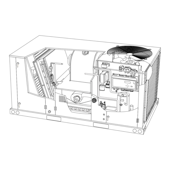
LGH/LCH036, 048, 060, & 072 DIMENSIONS in. - Gas heat section shown 85−1/4 (2165) BASE 5−5/8 16−1/4 (143) (279) (413) (457) 5 (102) 7 (178) BOTTOM RETURN OPENING BOTTOM (508) SUPPLY (737) 47 (1192) OPENING BASE CENTER 25−3/4 (654) GRAVITY 9−1/2 6−5/8 (241) - Page 5 LGH036, 048, 060, & 072 PARTS ARRANGEMENT REHEAD COIL EVAPORATOR BLOWER (OPTIONAL) COIL FILTERS (4) MOTOR 036, 048:16 X 20 X 2” CONDENSER (DIRECT DRIVE SHOWN) 060, 072: 20 X 20 X 2” ECONOMIZER (OPTIONAL) BLOWER COIL GUARDS (OPTIONAL) CONDENSER COIL CONDENSATE DRAIN...
-
Page 6: Shipping And Packing List
Shipping and Packing List NOTICE Package 1 of 1 contains: Roof Damage! 1- Assembled unit This system contains both refrigerant and oil. Some rubber roofing material may absorb oil, Check unit for shipping damage. Receiving party should causing the rubber to swell. Bubbles in the rubber contact last carrier immediately if shipping damage is found. -
Page 7: Unit Support
S Air filters must be replaced and pre-filters must be 5- Units require support along all four sides of unit base. removed upon construction completion. Supports must be constructed of steel or suitably S The input rate and temperature rise must be set per treated wood materials. -
Page 8: Horizontal Air Discharge
5- Install return air duct beneath outdoor air intake. See figure 4. Install barometric relief damper in lower *Weight IMPORTANT - ALL Unit Lbs. Kg. PANELS MUST hood and install in ductwork as shown in figure 4. BE IN PLACE FOR RIGGING. - Page 9 2- Lift the front edge of the drain pan and slide pan out CONDENSATE BOTTOM DRAIN CONNECTION of unit. See figure 9. REMOVE DRAIN PAN UNIT DRAIN PAN CAULK AROUND CONDENSATE COUPLING OPEN VENT DRAIN PAN MOUNTING FRAME Minimum Pitch FIGURE 9 1”...
-
Page 10: Gas Piping
4- From the inside of the pan, use a Vari-Bit bit to ® CAUTION enlarge the hole to 7/8”. Do not damage coupling threads. If a flexible gas connector is required or allowed by 5- Remove the cap over the unit bottom drain hole. the authority that has jurisdiction, black iron pipe 6- Slide the drain pan back into the unit. -
Page 11: Pressure Test Gas Piping
power to unit. These devices should be properly labeled BOTTOM ENTRY GAS PIPING COMPLETED by the installer. TO GAS PRESSURE TEST GAS LINE GROUND VALVE JOINT UNION STREET MANUAL MAIN ELBOW SHUT-OFF VALVE 7” NIPPLE TO GAS SUPPLY 2-1/2” NIPPLE GAS VALVE MANUAL MAIN SHUT-OFF VALVE... - Page 12 control box. Route power to TB2 on units equipped Thermostat Mode with electric heat. Route power to S48 or CB10 If 1- Route thermostat cable or wires from subbase to unit is equipped with the optional disconnect control area above compressor (refer to unit switch or circuit breaker.
- Page 13 16. Wire runs over 150 feet (mm): A2 SENSOR Use a local, isolated 24VAC transformer such as Lennox cat #18M13 (20VA minimum) to supply power to RH FIGURE 15 sensor as shown in figure 17. Use two shielded cables...
-
Page 14: Blower Operation And Adjustments
Blower Operation and Adjustments FIELD WIRING REHEAT UNITS (Using A Humidity Sensor With Less Than 150 Ft. Wire Runs) Three-, four- and five-ton units are equipped with either P298 J298A direct drive or multi-pole belt drive blowers. 6-ton units are available with belt drive blowers only. AI−1 IMPORTANT Three phase scroll compressors must be phased... - Page 15 LOCATION OF STATIC PRESSURE READINGS INSTALLATIONS WITH DUCTWORK INSTALLATIONS WITH CEILING DIFFUSERS ROOFTOP UNIT ROOFTOP UNIT RETURN AIR READING LOCATION RETURN AIR READING RE RE LOCATION SUPPLY SUPPLY TURN TURN FIRST BRANCH OFF OF MAIN RUN MAIN DUCT RUN SUPPLY AIR SUPPLY AIR READING READING...
- Page 16 BLOWER ASSEMBLY TO INCREASE CFM TO DECREASE CFM LOOSEN ALLEN SCREW & TURN PULLEY TURN PULLEY CLOCKWISE COUNTERCLOCKWISE SIDE VIEW LOOSEN ALLEN SCREW TO ADJUST CFM MOTOR ALLEN SCREW PULLEY TO INCREASE BELT TENSION 1-Loosen four bolts securing motor base to mounting frame.
- Page 17 3- Measure belt deflection force. For a used belt, the INSTALL BELT deflection force should be 5 lbs. (35kPa). A new belt deflection force should be 7 lbs. (48kPa). DRIVER TENSIONER force below these values indicates PULLEY undertensioned belt. A force above these values indicates an overtensioned belt.
- Page 18 Page 16...
- Page 19 Page 17...
- Page 20 Page 18...
- Page 21 BLOWER DATA - BELT DRIVE - 3 TON BLOWER TABLE INCLUDES RESISTANCE FOR BASE UNIT ONLY WITH DRY INDOOR COIL AND AIR FILTERS IN PLACE. FOR ALL UNITS ADD: 1 - Any factory installed options air resistance (heat section, economizer, etc.). 2 - Any field installed accessories air resistance (duct resistance, diffuser, etc.).
- Page 22 BLOWER DATA - BELT DRIVE - 3 TON BLOWER TABLE INCLUDES RESISTANCE FOR BASE UNIT ONLY WITH DRY INDOOR COIL AND AIR FILTERS IN PLACE. FOR ALL UNITS ADD: 1 - Any factory installed options air resistance (heat section, economizer, etc.). 2 - Any field installed accessories air resistance (duct resistance, diffuser, etc.).
- Page 23 BLOWER DATA - BELT DRIVE - 4 TON BLOWER TABLE INCLUDES RESISTANCE FOR BASE UNIT ONLY WITH DRY INDOOR COIL AND AIR FILTERS IN PLACE. FOR ALL UNITS ADD: 1 - Any factory installed options air resistance (heat section, economizer, etc.). 2 - Any field installed accessories air resistance (duct resistance, diffuser, etc.).
- Page 24 BLOWER DATA - BELT DRIVE - 4 TON BLOWER TABLE INCLUDES RESISTANCE FOR BASE UNIT ONLY WITH DRY INDOOR COIL AND AIR FILTERS IN PLACE. FOR ALL UNITS ADD: 1 - Any factory installed options air resistance (heat section, economizer, etc.). 2 - Any field installed accessories air resistance (duct resistance, diffuser, etc.).
- Page 25 BLOWER DATA - BELT DRIVE - 5 TON BLOWER TABLE INCLUDES RESISTANCE FOR BASE UNIT ONLY WITH DRY INDOOR COIL AND AIR FILTERS IN PLACE. FOR ALL UNITS ADD: 1 - Any factory installed options air resistance (heat section, economizer, etc.). 2 - Any field installed accessories air resistance (duct resistance, diffuser, etc.).
- Page 26 BLOWER DATA - BELT DRIVE - 5 TON BLOWER TABLE INCLUDES RESISTANCE FOR BASE UNIT ONLY WITH DRY INDOOR COIL AND AIR FILTERS IN PLACE. FOR ALL UNITS ADD: 1 - Any factory installed options air resistance (heat section, economizer, etc.). 2 - Any field installed accessories air resistance (duct resistance, diffuser, etc.).
- Page 27 BLOWER DATA - BELT DRIVE - 6 TON BLOWER TABLE INCLUDES RESISTANCE FOR BASE UNIT ONLY WITH DRY INDOOR COIL AND AIR FILTERS IN PLACE. FOR ALL UNITS ADD: 1 - Any factory installed options air resistance (heat section, economizer, etc.). 2 - Any field installed accessories air resistance (duct resistance, diffuser, etc.).
- Page 28 BLOWER DATA - BELT DRIVE - 6 TON BLOWER TABLE INCLUDES RESISTANCE FOR BASE UNIT ONLY WITH DRY INDOOR COIL AND AIR FILTERS IN PLACE. FOR ALL UNITS ADD: 1 - Any factory installed options air resistance (heat section, economizer, etc.). 2 - Any field installed accessories air resistance (duct resistance, diffuser, etc.).
-
Page 29: Blower Data
BLOWER DATA BELT DRIVE KIT SPECIFICATIONS - 036-060 Model Motor HP No. of Drive Kits and RPM Range Speeds Nominal Maximum 0.75 0.86 low 449-673 - - - - - - - - - - - - - - - high 673-1010 1.15 - - -... -
Page 30: Cooling Start-Up
TABLE 6 MANUFACTURER'S DRIVE COMPONENT NUMBERS DRIVE COMPONENTS Motor Pulley Blower Pulley bELT Drive No. Supplier No. OEM Part No. Supplier No. OEM Part No. Supplier No. OEM Part No. 1VP34x7/8 31K6901 AK54 x 1 100244-19 100245-17 1VP34x7/8 31K6901 AK49 x 1 100244-18 100245-16 1VP34x7/8... - Page 31 C-Refrigerant Charge and Check - All-Aluminum Coil charging curve to determine a target liquid temperature. WARNING-Do not exceed nameplate charge under any condition. Note - Pressures are listed for sea level applications. This unit is factory charged and should require no further 4- Use the same thermometer to accurately measure the adjustment.
- Page 32 TABLE 9 LGH/LCH048S NORMAL OPERATING PRESSURES - ALL-ALUMINUM COIL Outdoor Coil Entering Air Temperature 65 F 75 F 85 F 95 F 105 F 115 F Suct Disc Suct Disc Suct Disc Suct Disc Suct Disc Suct Disc (psig) (psig) (psig) (psig) (psig)
- Page 33 LGH/LCH036S CHARGING CURVE - ALL-ALUMINUM COIL Outdoor Temperature (°F) 115° 105° 95° 85° 75° 65° Suction Pressure (psig) LGH/LCH036H CHARGING CURVE - ALL-ALUMINUM COIL Outdoor Temperature (°F) 115° 105° 95° 85° 75° 65° Suction Pressure (psig) Page 31 LGH/LCH036, 048, 060, 072...
- Page 34 LGH/LCH048S CHARGING CURVE - ALL-ALUMINUM COIL Outdoor Temperature (°F) 115° 105° 95° 85° 75° 65° Suction Pressure (psig) LGH/LCH048H CHARGING CURVE - ALL-ALUMINUM COIL Outdoor Temperature (°F) 115° 105° 95° 85° 75° 65° Suction Pressure (psig) Page 32 LGH/LCH036, 048, 060, 072...
- Page 35 LGH/LCH060S CHARGING CURVE - ALL-ALUMINUM COIL Outdoor Temperature (°F) 115° 105° 95° 85° 75° 65° Suction Pressure (psig) LGH/LCH060H CHARGING CURVE - ALL-ALUMINUM COIL Outdoor Temperature (°F) 115° 105° 95° 85° 75° 65° Suction Pressure (psig) Page 33 LGH/LCH036, 048, 060, 072...
- Page 36 LGH/LCH072H CHARGING CURVE - ALL-ALUMINUM COIL Outdoor Temperature (°F) 115° 105° 95° 85° 75° 65° Suction Pressure (psig) Page 34 LGH/LCH036, 048, 060, 072...
- Page 37 C-Refrigerant Charge and Check - Fin/Tube Coil TABLE 15 LG/LC 036S REHEAT NORMAL OPERATING WARNING-Do not exceed nameplate charge under PRESSURES any condition. Outdoor Coil Discharge Suction + 5 This unit is factory charged and should require no further Entering Air Temp +10 psig psig adjustment.
- Page 38 TABLE 20 TABLE 25 LG/LC 060H REHEAT NORMAL OPERATING LG/LC 048H NORMAL OPERATING PRESSURES PRESSURES Outdoor Coil Discharge Suction + 5 Entering Air Temp +10 psig psig Outdoor Coil Discharge Suction + 5 Entering Air Temp +10 psig psig 655 F 655 F 755 F 755 F...
-
Page 39: Lgh/Lch036, 048,
TABLE 28 3- Freezestat (S49) APPROACH TEMPERATURE The compressor is protected by a freezestat located on the indoor coil. The freezestat opens at 29_F+3 LGH/LCH Unit Liquid Temp. Minus Ambient Temp. (-2_C+2) and closes at 58_F+4 (14_C+2). 036S & H Std. 036S &... -
Page 40: Gas Heat Start-Up
This unit is equipped with an automatic spark ignition Gas Heat Start-Up (Gas Units) system. There is no pilot. In case of a safety shutdown, FOR YOUR SAFETY READ BEFORE LIGHTING move thermostat switch to OFF and return the thermostat switch to HEAT to reset ignition control. -
Page 41: Heating Operation And Adjustments
5- Honeywell VR8205 Gas Valve with ON/OFF Lever - Heating Operation and Adjustments Switch gas valve lever to OFF. See figure 25. (Gas Units) Honeywell VR8205/8305 Gas Valve with Knob - Turn knob on gas valve clockwise to OFF. Do not force. A-Heating Sequence of Operation See figure 26. - Page 42 VCB Start-Up PT5 PRESSURE TRANSDUCER Units equipped with an A184 ventilation control board ECONOMIZER (VCB) allow the installer to enter the design-specified supply air CFM into the Unit Controller. In addition, the PRESSURE TRANSDUCER outdoor air flow (minimum damper position) can be entered.
- Page 43 TABLE 31 CEnter Outdoor Airflow Design Specifications Into MINIMUM / MAXIMUM CFM Unit Controller Use the following menu path to enter the outdoor airflow UNIT SIZE CFM (replaces minimum damper position set point) into Cooling High Speed & the Unit Controller. Make sure outdoor airflow CFM is Heating Maximum 1440 1920...
-
Page 44: Hot Gas Reheat Startup
SCR Electric Heat Controller (LCH Units) Hot Gas Reheat Start-Up And Operation General Optional factory-installed SCR (A38) will provide small Hot gas reheat units provide a dehumidifying mode of amounts of power to the electric heat elements to operation. These units contain a reheat coil adjacent to efficiently maintain warm duct air temperatures when and downstream of the evaporator coil. -
Page 45: Service
COOLING MODE REFRIGERANT ROUTING RETURN OUTDOOR EVAPORATOR EXPANSION COIL VALVE REHEAT COIL SUPPLY COMPRESSOR CONDENSER COIL CHECK VALVE REHEAT VALVE FIGURE 30 Check-Out Service Test reheat operation using the following procedure. 1- Make sure reheat is wired as shown in wiring section. The unit should be inspected once a year by a qualified 2- Make sure unit is in local thermostat mode. - Page 46 Clean burners as follows: WARNING 1- Turn off both electrical power and gas supply to unit. Units are shipped from the factory with temporary 2- Remove burner compartment access panel. filters. Replace filters before building is occupied. Damage to unit could result if filters are not re 3- Remove top burner box panel.
-
Page 47: Condensate Drains
4- Remove and retain screws securing combustion WARNING air inducer to flue box. Remove vent connector. See figure 35. Danger of explosion. Can cause injury or 5- Clean inducer wheel blades with a small brush and death. Do not overtighten main burner wipe off any dust from housing. - Page 48 G-Condenser Coil Fin/Tube Coils - Clean condenser coil annually with detergent or All-Aluminum Coils - commercial coil cleaner and inspect monthly during the Clean condenser coil annually with water and inspect cooling season. monthly during the cooling season. Condenser coils are made of single and two formed slabs. Clean the all-aluminum coil by spraying the coil steadily On units with two slabs, dirt and debris may become and uniformly from top to bottom.
- Page 49 See unit nameplate for manufacturer and address. 506372-01 12/2012 Supersedes11/2011 LGH036, 048 060, 072 (3, 4, 5 and 6 Tons) LGH092, 102, 120, 150 (7-1/2, 8‐1/2, 10 and 12 Tons) LGH156, 180, 210, 240, 300S (13, 15, 17-1/2, 20 and 25 Tons) LGH242, 300H, 360 (20, 25 and 30 Tons) ROOFTOP...
- Page 50 LGH036, 048, 060, & 072 Parts Arrangement REHEAT COIL EVAPORATOR BLOWER (OPTIONAL) COIL FILTERS (4) MOTOR 036, 048:16 X 20 X 2” CONDENSER (DIRECT DRIVE SHOWN) 060, 072: 20 X 20 X 2” ECONOMIZER (OPTIONAL) BLOWER COIL GUARDS (OPTIONAL) CONDENSER COIL CONDENSATE DRAIN...
- Page 51 LGH156, 180, 210, 240, 300S Parts Arrangement EVAPORATOR CONDENSER FILTERS ECONOMIZER COIL FANS (SIX - 24 X 24 X 2”) DAMPERS (OPTIONAL) (3 FANS ON 156 UNITS; 6 FANS BLOWERS ON 210, 240, & 300S UNITS UNIT CONTROLLER CONDENSER COILS (RIGHT COIL CONDENSATE IS VERTICAL ON DRAIN...
- Page 52 Safety CAUTION 1 - Keep unit area clear and free of combustible Label all wires prior to disconnection when servic ing controls. Wiring errors can cause improper and materials, gasoline and other flammable vapors and dangerous operation. Verify proper operation after liquids.
- Page 53 TYPICAL ELECTROMECHANICAL THERMOSTAT Honeywell VR8205 Gas Valve with ON/OFF Lever Single-Stage MANIFOLD MANIFOLD PRESSURE PRESSURE ADJUSTMENT OUTLET SCREW INLET PRESSURE PORT GAS VALVE SHOWN IN ON POSITION FIGURE 2 FIGURE 1 HONEYWELL VR8205Q/VR8305Q SERIES GAS VALVE HIGH FIRE LOW FIRE Placing Unit Into Operation ADJUSTMENT ADJUSTMENT...
- Page 54 HEAT EXCHANGER ASSEMBLY WARNING 092-150 UNITS HEAT Danger of explosion. Can cause injury or EXCHANGER death. Do not attempt to light manually. TUBE Unit has a direct spark ignition system. COMBUSTION AIR INDUCER Burner Flame WARNING Danger of explosion and fire. Can cause injury or product or property damage.
-
Page 55: Table
Servicing Filter TABLE 2 MANIFOLD PRESSURES in.wg. Units are equipped with filters as shown in table 1. Filters Natural Gas Propane (LP) Gas should be checked monthly and replaced when necessary. Take note of air flow direction marking on filter Unit Stage Stage... - Page 56 5- Remove and retain two screws from the bracket BURNER BOX ASSEMBLY supporting the vent connector before removing vent 092-360 UNITS VALVE connector. 024-150 units do not have a support bracket. See figure 4, 5, or 6. 6- Clean the inducer wheel blades with a small brush and wipe off any dust from the housing.
- Page 57 See unit nameplate for manufacturer INSTALLATION and address. 2011 INSTRUCTIONS Litho U.S.A. AGENCY REQUIRED RETAIN THESE INSTRUCTIONS FOR FUTURE REFERENCE PACKAGED GAS AND COOLING UNITS LGH036−360 UNITS 506373−01 11/2011 3 THROUGH 30 TONS Supersedes 9/2011 S Return air temperature range between 55°F (13°C) Table of Contents and 80°F (27°C) must be maintained.
- Page 58 United States LGH156, 180, 210, 240, 242, 300, 360 UNIT CLEARANCES The unit is ETL/CSA certified for outdoor installations only at the clearances to combustible materials listed on the Outdoor unit nameplate and in figures 1, 2 and 3. Air Hood LGH036, 048, 060, 072 UNIT CLEARANCES Number of...
-
Page 59: Connect Gas Piping
Never test for gas leaks with an open flame. Check all Honeywell VR8205 Gas Valve with ON/OFF Lever connections with a commercially available soap solution Single−Stage MANIFOLD MANIFOLD made specifically for leak detection. PRESSURE PRESSURE ADJUSTMENT OUTLET SCREW NOTE − Furnace must be adjusted to obtain a temperature rise (high and low fire) within the range(s) specified on the unit nameplate. -
Page 60: High Altitude Derate
Pressure Test Gas Piping BOTTOM ENTRY GAS PIPING COMPLETED Operating pressures at the unit gas connection must be TO GAS GROUND as shown in table 2. VALVE JOINT UNION TABLE 2 OPERATING PRESSURE AT GAS CONNECTION w.c. STREET ELBOW Natural Gas LP / Propane Gas Min. -
Page 61: Two Stage Gas Valve Adjustment
Two−Stage Gas Valve Adjustment Proper Gas Flow (Approximate) 1− Operate unit at least 15 minutes before checking gas Gas manifold pressures should match pressures shown flow. Determine the time in seconds for two in table 3. On two stage gas valves, initiate a W2 revolutions of gas through the meter. -
Page 62: Typical Gas Heat Schematic
TYPICAL GAS HEAT SCHEMATIC This schematic is typical. See the wiring schematic on the unit for actual unit wiring. Page 6 LGH036−360 Agency... -
Page 63: Typical Unit Schematic
TYPICAL UNIT SCHEMATIC This schematic is typical. See the wiring schematic on the unit for actual unit wiring. Page 7 506373−01 11/2011... -
Page 64: Repair Parts Listing
Repair Parts Listing When ordering repair parts, include the complete model number and serial number listed on the ETL/CSA rating plate − e.g. LGH120H4BH1Y. Gas Heat Section Parts Cooling Parts Electrical Control Parts Heat Exchanger Compressors Unit Controller Combustion Air Assembly Condenser Fan Motors Compressor Contactors Combustion Air Proving Switch... -
Page 65: Table
M2 unit controller signal reference diagram ..® For all available Prodigy documentation, see the Lennox M2 unit controller board connections diagram ..Commercial website (www.lennoxcommercial.com). -
Page 66: Usb Firmware Update
M2 (A55) unit controller - location, controls, inputs/outputs USB Firmware update Prodigy USB Flash Drive Update Capability Flash Drive Updating M2 version USB firmware updating is only available on Prodigy Display, Supported M2 Board? (DB), firmware versions v1.09.xx and later. To read the 7.0x.xx (no suffix) display firmware version, navigate to menu DATA >... -
Page 67: Smartwiret Connections
It will take a few minutes to update the M2 board with the new files should be in the root folder of the thumb drive. If located firmware. After reaching 100%, M2 UPDATE COMPLETE anywhere else the Prodigy will not find the DB1 file. will display first;... -
Page 68: Startup
M2 unit controller LED indicators Some indicators on the circuit board are visible with the cover in place; others are not. The indicators and their meanings are described in table 1. Table 1. LED operation indications Status Indication Meaning Status Indication Meaning RX (GREEN) - Page 69 Startup (continued) User interface menu at the time, in priority order of top-to-bottom of the left column in figure 2. For example, if an alarm is present, that will be The user interface is accessed through the menu navigation displayed until it has been silenced or cleared. arrows and the select button .
-
Page 70: Menu Interface
Menu Interface Table 2. Menu Interface (cont'd) Table 2 shows the major levels of the menu interface. Many Level 1 Level 2 Level 3 of these options have more levels and are described in the POWER ON following sections that detail DISPLAY, SERVICE, DATA, FILTER: XX HRS BELT: XX HRS and SETTINGS. -
Page 71: Display
DISPLAY Interface DISPLAY The display shows operating mode if in normal operation. Unit Operation Alarm, status, calls and plugging in the USB will interrupt the This section describes the display and control buttons, how display. Alarm messages will stay displayed until corrected or to configure the unit, and how to read stored configuration silenced using the local menu. - Page 72 Multiple units may use the same USB drive. The filename of the service reports will be based on the unit's serial number; When the Lennox USB drive is plugged in during normal for example 5608J5875.txt. The filename of the unit profiles MODE, a menu will be displayed providing options to save will be based on the unit's catalog number;...
-
Page 73: Guided Setup
GUIDED SETUP Menu Interface GUIDED SETUP Upon initial unit start-up, the M2 Unit Controller's menu This guided setup is available at any time should you wish to interface defaults to a GUIDED SETUP. This setup is go back through and re-configure the system's setup described on this and the following page. - Page 74 GUIDED SETUP Menu Interface GUIDED SETUP (Continued) (SYSTEM CHECKS UNIT CONFIGURATION AND PROMPTS THE USER FOR ONLY THE INSTALLED OPTION[S].) MSAV HIGH SPEED XXX% MSAV LOW SPEED XXX% CHANGE SETUP MSAV MSAV See Page 19 for complete MSAV details ! SET ! SETTINGS? EQUIP...
-
Page 75: Service
SERVICE Menu Interface SERVICE From the DISPLAY mode, press and then use SERVICE > IN / OUTPUTS scroll to SERVICE. Next, press to enter the SERVICE In the SERVICE menu, use until IN / OUTPUTS is menu. Use until desired item is displayed. displayed. -
Page 76: Test
SERVICE Menu Interface SERVICE (Continued) SERVICE > TEST (Continued) Table 4. TEST NOTE: Unit configuration determines TEST GUIDED which menu items are displayed blower BLOWER BLOWER HI BL OFF/ON maximum speed blower BLOWER LOW BL OFF/ON minimum speed Display status of the switch PROVING SWITCH PSW CLO with blower low speed. -
Page 77: Data
DATA Menu Interface DATA From the DISPLAY mode, press and then use DATA > HISTORY scroll to DATA. Next, press to enter the DATA menu. Use In the DATA menu, use until HISTORY is displayed. until desired item is displayed. Press to enter the HISTORY menu. - Page 78 DATA Menu Interface DATA (Continued) DATA > NETWORK Use the up/down arrows to scroll through the read In the DATA menu, use until NETWORK is displayed. able entries. Use the se Press to enter the NETWORK menu. Read the lect button to view data. NETWORK addresses stored in the M2 unit controller.
-
Page 79: Settings
SETTINGS Menu Interface SETTINGS From the DISPLAY mode, press and then use SETTINGS > SETPOINTS > COOLING scroll to SETTINGS. Next, press to enter the SETTINGS HEATING REHEAT menu. Use until desired item is displayed. EXHAUST Use SETTINGS to make changes to the Unit Controller after initial installation. - Page 80 SETTINGS > SETPOINTS > DAMPER Use SETTINGS > SETPOINTS > DAMPER as shown in the following diagrams; default settings will be used. You may adjust those settings to suit the building's requirements. NOTE - Early hardware used pots and DIP switches; newer hardware does not. Newer hardware Early hardware NOTE: FOR...
- Page 81 SETTINGS Menu Interface SETTINGS (Continued) SETTINGS > CONTROL SETTINGS > CONTROL > LOCAL In the SETTINGS menu, use until CONTROL is (Used in absence of thermostat or network control) displayed. Press to enter the CONTROL menu access/change system setpoints. Select SETTINGS > CONTROL > LOCAL as shown in the following diagram;...
- Page 82 SETTINGS Menu Interface SETTINGS (Continued) SETTINGS > CONTROL > BACnet Select SETTINGS > CONTROL > BACnet as shown in the following diagram; default settings will be used. You may adjust those settings to suit the building's requirements. The following diagram shows the BACnet menu's structure and how to make changes.
- Page 83 SETTINGS Menu Interface SETTINGS (Continued) SETTINGS > CONTROL > MSAV Select SETTINGS > CONTROL > MSAV as shown in the following diagram; default settings will be in place. You may (Multi‐stage air volume) adjust those settings to suit the building's requirements. The following diagram shows the MSAV menu's structure and illustrates how to use the controls to make changes.
- Page 84 SETTINGS > CONTROL > MSAV > DAMPER Select SETTINGS > CONTROL > MSAV > DAMPER as shown in the following diagram; default settings will be in (Multi‐stage air volume) place. You may adjust those settings to suit the building's requirements. The following diagram shows the MSAV menu's structure and illustrates how to use the controls to make changes.
-
Page 85: Install New M2
SETTINGS Menu Interface SETTINGS (Continued) SETTINGS > CONTROL > ECTO versions that do not end in "H". If the display does not have a HOST boot-loader (indicated by the H), then a Windows PC When you select ECTO, default settings will be in place. You and USB cable (AtoA, or with BtoA adapter) are needed to may adjust those settings to suit the building's requirements. - Page 86 SETTINGS > INSTALL > NEW M2 Use SETTINGS > INSTALL > NEW M2 to go through the setup and change settings as needed when installing a replacement M2 (new M2 units have no factory pre-sets). INSTALL CLEAR ARE YOU NEW M2 SURE? WHEN INSTALLING A NEW M2, ENTER THE SERIAL, UNIT NO.
-
Page 87: Economizer (Damper)
Economizer (Damper) General During free cooling operation, the damper modulates to maintain a discharge air temperature equal to the free The economizer, when configured, controls cooling discharge air setpoint. If the damper has been damper position, which determines how much outdoor continuously at its maximum open position for at least three air is used to meet free cooling or indoor air quality (IAQ) minutes, then a second stage cooling demand will be allowed... - Page 88 Economizer (Damper) (Continued) There are six options available to determine outdoor air factory-configured. When economizer suitability (OAS) for free cooling. See table 6. Economizer field-configured, the ODE mode requires additional settings are shown for each mode in figure 4. field-provided sensor(s). See table 6. The TEMP mode uses sensors provided with all units.
- Page 89 Economizer Controls and Location Free Cooling Settings Note-All economizer modes of operation, except DSET, will modulate dampers to 55°F (13°C) discharge air. TEMP OFFSET, TEMP OAT STPT, and Remote MODE. M2 UNIT CONTROLLER ODE DIFFERENTIAL (Outdoor Enthalpy) Set to DIF STEADY YELLOW ENTH SET PNT “OUTDOOR AIR...
-
Page 90: Appendix
M2-1 Display battery (10-pack) 59W53 SmartWiret Field Termination kit 59W57 MCB1 M2 Motor Control Replace 59W50 M2-1 Fuse (2-Amp ATC, 5-pack) 59W54 Lennox Prodigy USB Memory Stick 59W59 ment kit (5-pack) M2 BACnett Replacement kit 59W51 M2 Deluxe Training kit (suitcase, 59W55 Service Software &... -
Page 91: Usb Service Report Example
USB Service Report Example ========================================================================== USB SERVICE REPORT ========================================================================== Service Date 1/1/2010 Service Time 12:00:00 Serial No. 5609K00002 Version 7.02.00 DB1Version 1.05.00 Unit No. Sbus Address BACnet Address. CAT No. NO CN MODEL NO. LGH036H4ES1Y Status HEATING ========================================================================== Runtime Data Total Power On 1832 HRS 79 CYCLES... - Page 92 USB Service Report Example (If SmartAirflow™ is Installed) ======================================================================== ======================================================================== SmartAirflow USB SERVICE REPORT ======================================================================== Calibrated on 9/27/2012 13:10:49 Service Date 10/26/2009 Supply Airflow Calibration Table Service Time 16:28:05 Serial No. 5609K00002 PWM(%) Speed(rpm) Airflow(cfm) Version 7.00.00 ...
- Page 93 USB Service Report Example (If SmartAirflow™ is Calibrated) SmartAirFlow Page 29...
- Page 94 Page 30...
- Page 95 Page 31...
- Page 96 Page 32...
- Page 97 Page 33...
-
Page 98: Wiring Diagrams
Wiring Diagrams (036, 048, 060 Units) Page 34... - Page 99 Wiring Diagrams (ACCESSORIES) Page 35...
- Page 100 Wiring Diagrams (ACCESSORIES) J299A P299 DI-1 USE DI2 TO CONNECT: 1. OVERLOAD CONTACTS DI-2 DI-3 DI-4 USE DI3 TO CONNECT: 1. OVERFLOW SWITCH P304 2. PHASE MONITOR MODULE A130 TB37 Page 36...
- Page 101 Wiring Diagrams (240, 300 Units) Page 37...
- Page 102 COMPONENT PANEL, MAIN PANEL, COMPRESSORS 3 AND 4 A169 PANEL, MOTOR CONTROL A184 CONTROL, VCB BOARD COMPRESSOR 1 COMPRESSOR 2 MOTOR, BLOWER MOTOR, OUTDOOR FAN 1 MOTOR, OUTDOOR FAN 2 MOTOR, EXHAUST FAN 1 MOTOR, EXHAUST FAN 2 COMPRESSOR 3 COMPRESSOR 4 MOTOR, OUTDOOR FAN 3 MOTOR, OUTDOOR FAN 4...
- Page 103 K152,-1 RELAY, OUTDOOR FAN 5 K153,-1,2 RELAY, OUTDOOR FAN 6 VALVE, SOLENOID REHEAT COIL 1 VALVE, SOLENOID REHEAT COIL 2 PLUG, EXHAUST FAN COMP PLUG, EXHAUST FAN PLUG, OUTDOOR FAN 1 PLUG, OUTDOOR FAN 2 PLUG, OUTDOOR FAN INTERFACE PLUG, OUTDOOR FAN INTERFACE 2 P106 PLUG, OUTDOOR FAN 3 P107...
- Page 104 Page 40...
- Page 105 P270 DISPLAY PCB Page 41...
-
Page 106: Quick Start Guide (Back Cover)
Refer to Economizer section of manual for more (Page 16). detail Reheat Select sensor type; see possible connections, SENSOR SETTINGS -> CONTROL -> REHEAT HUMIDISTAT (Page 18). Analog sensor wiring is polarity sensitive For Lennox Service Support 1-800-4LENNOX. For Lennox Commercial website, go to www.lennoxcommercial.com. Page 42... -
Page 107: Table
Revision History 12/2009 Initial production release. 6/2011 Revised software support; (3/11); add LONTALK in table on page 4; remove SmartWire Repair Tool Kit 11/2011 New firmware upload procedures; MSAV additions. 3/2013 Change diagram 537108-01 to 537108-02; revise trademarks throughout manual; added error code 147; DB1 menu changes;... - Page 109 ECONOMIZERS 507030−01 Litho U.S.A. E1ECON ECONOMIZERS 5/2012 2012 Supersedes 506197−01 INSTALLATION INSTRUCTIONS FOR ECONOMIZERS AND OUTDOOR AIR HOODS USED WITH LG/LC 036, 048, 060, 072 UNITS Note − Disregard economizer installation section when WARNING dampers are factory−installed. Shipping and Packing List Improper installation, adjustment, alteration, ser- vice or maintenance can cause property damage, Package 1 of 1 contains:...
- Page 110 TABLE 3 REMOVE SENSORS AND BRACKET Field−Provided Dampers will modulate to 55°F Mode Sensors discharge air (RT6) when: OA temp. (RT17) is less than RA temp. (RT16) or when the Energy None Needed Management System sends an economizer enable message.** OA enthalpy* (A7) is less than C7400 enthalpy setpoint.
- Page 111 ECONOMIZER INSTALLATION ECONOMIZER DAMPER MOTOR UNIT SMOKE DETECTOR (WHEN EQUIPPED) A2 SENSOR (UNITS WITH DDC CONTROL) RT16 SENSOR RETURN AIR OPENING FIGURE 4 Page 3...
- Page 112 GED (Barometric Relief Dampers) Outdoor Air Hoods Note − GED is optional when economizer is factory−installed. Factory−Installed Economizers Only − Remove GED from the economizer (when present) and Both hood tops and pivot brackets are secured to unit. install in the exhaust air hood when: The lower hood is provided and installed only when the SOptional power exhaust fans are installed economizer is equipped with an optional GED.
- Page 113 ASSEMBLE HOODS OUTDOOR AIR HOOD SECURE TOP BRACKET WITH SCREW AFTER BIRDSCREEN BIRDSCREEN IS IN PLACE INSTALL LOWER BRACKET BEFORE INSTALLING BIRDSCREEN EXHAUST OR LOWER HOOD LOWER HOOD INSTALLED ONLY WHEN ECONOMIZER IS EQUIPPED WITH A GED GED INSTALLED IN HOODS WHEN POWER EXHAUST IS PRESENT.
- Page 114 INSTALL HOODS SIDE VIEW CAULK UNIT TOP PIVOT BRACKET MULLION HOOD CAULK INTAKE LOWER HOOD INSTALLED ONLY WHEN ECONOMIZER IS EQUIPPED WITH A GED EXHAUST FIGURE 8 Page 6...
- Page 115 Install Economizer − Horizontal HORIZONTAL AIRFLOW A field fabricated return air duct transition and duct inlet BACK must be installed in horizontal applications. OF UNIT 1− Remove unit end panel. See figure 9. 2− Install the downflow return air cover in horizontal airflow applications.
-
Page 117: Table
Figure 1. Check M1−7, M1−8 Software Version 1− Wiring diagram and Address Technical Assistance WARNING For assistance contact Lennox Technical Support at Improper installation, adjustment, alteration, ser- 800−453−6669. vice or maintenance can cause property damage, Version Required personal injury or loss of life. Installation and ser- vice must be performed by a qualified installer or This module requires a rooftop unit IMC M1−7 (version 5.02... -
Page 118: Application
Position the mounting plate manual. beneath the IMC board as shown in figure 4. Secure Either a Lennox zone sensor or a LonTalk network zone sen- with four #6 screws. sor is required to send the zone temperature to the unit con- 4. - Page 119 LONTALK S−Class − E Box 420−600 MODULE LONTALK MODULE Figure 3. LonTalk Module (036−060 units, A box) Figure 4. LonTalk Module (420/600 units, E Box) ALIGN DIMPLES IN UNIT MOUNTING MULLION WITH ENGAGING PLATE HOLE IN MOUNTING PLATE FLANGE; SECURE WITH 5/8" SHEET METAL SCREW.
-
Page 120: Imc Manual
1. Set ECTO 6.01 to option 3 (zone sensor system mode Install the sensor according to manufacturer’s instructions. with return air sensor back−up). NOTE − Lennox zone sensor requires twisted pair shielded 2. Set ECTO 6.17 to option 1 (continuous blower during cable. -
Page 121: Communications Check Out
LonTalk Zone Sensor Installed: SETTINGS 1. Set ECTO 6.01 to option 3 (zone sensor system mode with return air temperature back−up). CONTROL 2. Set ECTO 6.17 to option 1 (continuous blower during occupied). LONTALK 3. Set ECTO 5.27 to option 2 (network zone sensor op- MONITOR ONLY tion). -
Page 122: Lonworks Network Connection
to a maximum of 64 nodes per segment. The maximum to- LonWorks Network Connection tal bus length and the maximum node−to−node length is 1640 ft. (500m) for Belden 8471 or NEMA Level 4. Maxi- The LonTalk module has an FTT−10A Free Topology mum lengths are less for other smaller wire size cables. -
Page 123: Network Integration
60°F, cooling = 85°F) and the current zone temperature A network configurating tool such as LonMaker® is re- read by an additional Lennox zone sensor if installed. If the quired to commission the LonWorks network. Press the Lennox zone sensor is not installed, the return air tempera- service button on the LonTalk module to generate a service ture sensor is used as backup (ECTO 6.01). -
Page 124: Alarm Codes
3− Unit controller attempts to use Lennox zone 4− Unit controller attempts to use Lennox zone sensor as backup. If sensor as backup. If this fails, Unit controller this fails, Unit controller uses return air sensor backup. uses return−air−sensor backup. - Page 125 The module is LonMark certified to design guide work. lines version 3.4. Technical Assistance WARNING For assistance, contact Lennox Technical Support at 800-453-6669. Improper installation, adjustment, alteration, ser Installation vice or maintenance can cause personal injury, loss of life, or damage to property.
- Page 126 Operation and Functional Description ® LonWorks Network Connection to a maximum of 64 nodes per segment. The maximum to tal bus length and the maximum node-to-node length ® The LonTalk module has an FTT-10A Free Topology is1640 ft. (500 m) for Belden 8471 or NEMA Level 4. Maxi Transceiver for network communication.
- Page 127 Space Comfort Controller- terface File (XIF) is available for configuration prior to Rooftop and Discharge Air Controller. It also contains a installation. Lennox specified functional block, a virtual function block ® containing the network configuration variables and a node Prodigy Reset object.
- Page 128 SupFanStatusu nvoBlowTorqueu nvoUnitStatus1u nvoOAFlowu lennox dischargeAirCont wnciBldgStaticSP wnciBypassTime wnciDACISP wnciDAHtSP wnciDuctStatSP wnciFanOperation wnciLocation wnciOAMinPOS unviRequest nvoStatu wnciOATSP wnciSetpoints wnciSndHrtBt wnciSpaceRHSetpt NodeObject wnciSupAFSP wnciMinOAFSP Virtual Functional Blocks Figure 4.
- Page 129 Table 1. Network Variables (sorted alphabetically) SNVT SNVT SNVT In Index Index SNVT Name SNVT Name SNVT Name nciBldgStaticSP nviSetpoint nvoOAFlow nciBypassTime nviSetptOffset nvoOutdoorTemp nciDAClSP nviSpaceDehumSP nvoRATemp nciDAHtSP nviSpaceIAQ nvoRecentEvent_1 nciDuctStatSP nviSpaceRH nvoRecentEvent_2 nciFanOperation nviSpaceTemp nvoRecentEvent_3 nciLocation nviSupFanCap nvoRecentEvent_4 nciMinOAFlowSP nvoAirflow nvoRecentEvent_5 nciOAMinPos...
- Page 130 Table 2. Network Variable Definitions SNVT In Send Functional Block Application Description Heartbeat Name Type A value of 0 (zero), turns off the Send Heartbeat function. Values between .01 seconds and 10 are nciSndHrtBt SNVT_time_sec Virtual Functional Block — treated as 10 seconds. (10 seconds is the minimum heartbeat supported rate.) nciLocation SNVT_str_asc...
- Page 131 SNVT In In Send Send Functional Block Functional Block Application Description Application Description Heartbeat Heartbeat Name Type Used to command the Space Comfort Controller nviOccManCmd SNVT_occupancy sccRooftop — into different occupancy mode Used to indicate the presence of occupants in the nviOccSensor SNVT_occupancy sccRooftop...
- Page 132 SNVT In In Send Send Functional Block Functional Block Application Description Application Description Heartbeat Heartbeat Name Type Reports the current primary heat output value. nvoHeatPrimary SNVT_lev_percent sccRooftop Reports the current secondary heat output value, nvoHeatSecondary SNVT_lev_percent sccRooftop (heat pumps only). nvoCoolPrimary SNVT_lev_percent sccRooftop...
- Page 133 Valid ranges are 40-to-95 F (COOLING). The cool ing setpoints must be above the corresponding nviHCSetpoints SNVT_temp_setpt lennox — heating setpoint by the unit's Autochangeover Deadband (ECTO 6.15, 3 F default). The Standby setpoints are not used by the Application Reports zone temperature setpoints.
- Page 134 Functional Block Application Description Application Description Heartbeat Heartbeat Name Type Reports second most recent alarm with time of oc- nvoRecentEvent_2 UNVT_event lennox currence. Reports alarm with time of occurrence. nvoRecentEvent_3 UNVT_event lennox Reports alarm with time of occurrence. nvoRecentEvent_4 UNVT_event lennox Reports alarm with time of occurrence.
- Page 135 Table 3. Variable Type Definitions SNVT Type Definition SNVT Type Definition SCPTfanOperation fan_operation_t SNVT_time_min Elapsed Time Enumeration, 1 byte Signed Long, 2 bytes Value Identifier Notes Valid Range: 0 .. 65,535 Minutes -1 (0xFF) HVF_NUL Invalid Value Resolution: 1 Minute 1 HVF_CYCLE Fan cycles with heating and SNVT_time_sec Elapsed Time...
- Page 136 Network Configuration Parameter Implementation Table 4 shows which Prodigy ECTO (Electronic Config To Order) parameters are updated with Network Configuration Pa rameter (nci) parameter updates. Refer to Prodigy Application Guide for ECTO details. Table 4. Network Configuration Parameter to Electronic-Config-To-Order Parameter Relationships ECTO ECTO nciBldgStaticSP...
- Page 137 Appendix A The maximum and minimum values of Supply Airflow Targets in CFM units are as below in CFM as well as in lit/sec units. UNIT SIZE 36 (3 ton) 48 (4 ton) 60 (5 ton) Units lit/sec lit/sec lit/sec Maximum High Speed Target &...
Need help?
Do you have a question about the LGH 036 and is the answer not in the manual?
Questions and answers