Table of Contents
Advertisement
Quick Links
Service Literature
The LGH/LCH high and standard efficiency 35, 40, 45 and
50 ton (123, 140.7, 158.3 and 175.9 kW) units, are config
ure to order units (CTO) with a wide selection of factory in
stalled options. The LGH/LCH rooftop units are available in
500,000 Btuh or 800,000 Btuh (146.5 kW or 234.4kW)
heating inputs. Gas heat sections are designed with alu
minized steel tube heat exchangers. LGH and LCH units
are equipped with the same cooling sections and cooling
components. The LGH/LCH units utilize four scroll com
pressors with each compressor equipped with a crankcase
heater.
LGH/LCH units are designed for R-410A (high efficiency).
Service equipment for R-410A units must be rated for
R-410A refrigerant.
Optional electric heat is factory installed in LCH units. Electric
heat operates in single or multiple stages depending on the
kW input size. 30kW through 90kW heat sections are avail
able for the LCH units in all voltages G, J and Y while105kW
through 180kW heat sections are available for LCH G and J
voltage units only.
IMPORTANT
Improper installation, adjustment, alteration, service
or maintenance can cause property damage, person
al injury or loss of life. Installation and service must
be performed by a qualified installer or service agen
cy.
Corp. 1018-L1
01-2010
LGH/LCH SERIES
The LGH/LCH units are designed to accept any of several
different energy management thermostat control systems
with minimum field wiring. Factory or field provided control
options connect to the unit with jack plugs. When "plugged
in" the controls become an integral part of the unit wiring.
If the unit must be lifted for service, rig unit by attaching eight
cables to the holes located in the unit base rail (two holes at
each corner and center of frame). Refer to the installation in
structions for the proper rigging technique.
Information contained in this manual is intended for use by
qualified service technicians only. All specifications are
subject to change. Procedures outlined in this manual are
presented as a recommendation only and do not super
sede or replace local or state codes.
Danger of sharp metallic edges. Can cause injury.
Take care when servicing unit to avoid accidental
contact with sharp edges.
LGH/LCH
35, 40, 45, 50 TON
(123, 140.7, 158.3, 175.9 kW)
WARNING
Electric shock hazard. Can cause injury
or death. Before attempting to perform
any service or maintenance, turn the
electrical power to unit OFF at discon
nect switch(es). Unit may have multiple
power supplies.
CAUTION
Advertisement
Table of Contents

Related Manuals for Lennox LGH


Summary of Contents for Lennox LGH
-
Page 1: Introduction
01-2010 Service Literature LGH/LCH SERIES The LGH/LCH high and standard efficiency 35, 40, 45 and The LGH/LCH units are designed to accept any of several 50 ton (123, 140.7, 158.3 and 175.9 kW) units, are config different energy management thermostat control systems ure to order units (CTO) with a wide selection of factory in... -
Page 2: Table Of Contents
TABLE OF CONTENTS Introduction ......Page 1 V-MAINTENANCE ..... . . Page 73 Options / Accessories . -
Page 3: Options/Accessories
OPTIONS/ACCESSORIES Item Factory Field COOLING SYSTEM Corrosion Protection - Condenser and Evaporator Coils Drain Pan Overflow Switch High Efficiency - R-410A (35, 40 Ton Models) Hot Gas Bypass (Not available with Humiditrol Option) Standard Efficiency - R-410A (35, 40, 45, 50 Ton Models) Service Valves Spring Isolation (compressor deck) HEATING SYSTEM... - Page 4 OPTIONS/ACCESSORIES Item Factory Field ELECTRICAL Voltage (60HZ) - 208/230V-3 phase, 460V-3 phase or 575V-3 phase HACR Circuit Breakers - 70, 80, 90, 100, 110, 125, 150, 175, 200, 225, 250 amp Disconnect Switch - 150, 250 amp GFI Service Outlets (field wired) GFI Service Outlets (powered) HUMIDITROL CONDENSER REHEAT (CAV UNITS ONLY)
-
Page 5: Specifications
SPECIFICATIONS - OPTIONAL POWER EXHAUST FANS Standard Static PEF (No.) Motor output (1) 1 hp (50%) Motor rpm 1140 (No.) Diameter - in. (1) 26 No. of blades Standard Static PEF (No.) Motor output (2) 1 hp (100%) Motor rpm 1140 (No.) Diameter - in. -
Page 6: Cooling Performance
SPECIFICATIONS - 35 TON STANDARD EFFICIENCY General Nominal Tonnage 35 Ton 35 Ton Data Model No. LGH420S4B LGH420S4V Efficiency Type Standard Standard Blower Type Constant Air Volume (CAV) Variable Air Volume (VAV) Cooling Gross Cooling Capacity - Btuh 435,000 433,000 Performance Net Cooling Capacity - Btuh 410,000... - Page 7 SPECIFICATIONS - 35 TON HIGH EFFICIENCY General Nominal Tonnage 35 Ton 35 Ton Data Model No. LGH420H4B LGH420H4V Efficiency Type High High Blower Type Constant Air Volume (CAV) Variable Air Volume (VAV) Cooling Gross Cooling Capacity - Btuh 443,000 443,000 Performance Net Cooling Capacity - Btuh 420,000...
- Page 8 SPECIFICATIONS - 40 TON STANDARD EFFICIENCY General Nominal Tonnage 40 Ton 40 Ton Data Model No. LGH480S4B LGH480S4V Efficiency Type Standard Standard Blower Type Constant Air Volume (CAV) Variable Air Volume (VAV) Cooling Gross Cooling Capacity - Btuh 502,000 476,000 Performance Net Cooling Capacity - Btuh 470,000...
- Page 9 SPECIFICATIONS - 40 TON HIGH EFFICIENCY General Nominal Tonnage 40 Ton 40 Ton Data Model No. LGH480H4B LGH480H4V Efficiency Type High High Blower Type Constant Air Volume (CAV) Variable Air Volume (VAV) Cooling Gross Cooling Capacity - Btuh 491,000 494,000 Performance Net Cooling Capacity - Btuh 470,000...
- Page 10 SPECIFICATIONS - 45 TON STANDARD EFFICIENCY General Nominal Tonnage 45 Ton 45 Ton Data Model No. LGH540S4B LGH540S4V Efficiency Type Standard Standard Blower Type Constant Air Volume (CAV) Variable Air Volume (VAV) Cooling Gross Cooling Capacity - Btuh 554,000 549,000 Performance Net Cooling Capacity - Btuh 525,000...
- Page 11 SPECIFICATIONS - 50 TON STANDARD EFFICIENCY General Nominal Tonnage 50 Ton 50 Ton Data Model No. LGH600S4B LGH600S4V Efficiency Type Standard Standard Blower Type Constant Air Volume (CAV) Variable Air Volume (VAV) Cooling Gross Cooling Capacity - Btuh 607,000 598,000 Performance Net Cooling Capacity - Btuh 575,000...
-
Page 12: Specifications - Gas Heat
SPECIFICATIONS - GAS HEAT Gas Heating Heat Input Type Standard High Performance 2 Stage 2 Stage (2 Stage) Input - First Stage Btuh (kW) 330,000 (96.6) 528,000 (154.6) Input - Second Stage Btuh (kW) 500,000 (146.4) 800,000 (234.4) Output - First Stage Btuh (kW) 264,000 (77.3) 422,400 (123.7) -
Page 13: Blower Data
BLOWER DATA BLOWER TABLE INCLUDES RESISTANCE FOR BASE UNIT ONLY WITH DRY INDOOR COIL, HIGH GAS HEAT, ECONOMIZER, ONE ROW REHEAT COIL & AIR FILTERS IN PLACE Add factory installed options air resistance, then determine from blower table blower motor output and drive kit required. See page 19 for horizontal configured unit air resistance. - Page 14 BLOWER DATA BLOWER TABLE INCLUDES RESISTANCE FOR BASE UNIT ONLY WITH DRY INDOOR COIL, HIGH GAS HEAT, ECONOMIZER, ONE ROW REHEAT COIL & AIR FILTERS IN PLACE Add factory installed options air resistance, then determine from blower table blower motor output and drive kit required. See page 19 for horizontal configured unit air resistance.
- Page 15 BLOWER DATA POWER EXHAUST FANS 50% HIGH STATIC OPERATION, NO ERW Return Duct Negative Static Pressure - Inches Water Gauge (Pa) Volume RPM BHP RPM BHP RPM BHP RPM BHP RPM BHP RPM BHP RPM BHP RPM BHP RPM BHP RPM BHP RPM BHP 4000 410 0.75 465 1.00 520 1.25 575 1.50...
- Page 16 BLOWER DATA POWER EXHAUST FANS 50% HIGH STATIC OPERATION WITH ERW (BY-PASS DAMPERS CLOSED) Return Duct Negative Static Pressure - Inches Water Gauge (Pa) Volume RPM BHP RPM BHP RPM BHP RPM BHP RPM BHP RPM BHP RPM BHP RPM BHP RPM BHP RPM BHP RPM BHP 2500 390 0.35 460 0.50 530 0.70 600 0.90...
- Page 17 BLOWER DATA POWER EXHAUST FANS 50% HIGH STATIC OPERATION WITH ERW IN ECONOMIZER MODE (BY-PASS DAMPERS OPEN) Return Duct Negative Static Pressure - Inches Water Gauge (Pa) Volume RPM BHP RPM BHP RPM BHP RPM BHP RPM BHP RPM BHP RPM BHP RPM BHP RPM BHP RPM BHP RPM BHP 3500 380 0.55 435 0.70 495 0.90 555 1.10...
- Page 18 BLOWER DATA POWER EXHAUST FANS STANDARD STATIC ( TWO FAN OPERATION) Return Duct Return Duct Air Volume Air Volume Negative Static Pressure Negative Static Pressure Inches Water Gauge Inches Water Gauge 12,100 0.50 5700 0.05 11,600 0.55 5000 0.10 11,150 0.60 4300 0.15...
- Page 19 BLOWER DATA AIR RESISTANCE HORIZONTAL AIRFLOW APPLICATIONS Standard Static Power Exhaust fans 50% High Static 100% High Static Air Volume Power Exhaust Fans Power Exhaust Fans No Power Exhaust Fans in. w.g. in. w.g. in. w.g. 10,000 10,500 11,000 11,500 12,000 12,500 13,000...
- Page 20 BLOWER DATA FACTORY INSTALLED OPTIONS AIR RESISTANCE ECONOMIZER RETURN AIR DAMPER WITH ERW Outdoor Air Volume Return Duct Negative Static Pressure 0 in. w.g. With ERW 3250 0.32 0.12 - - - - - - - - - 3500 0.36 0.16 - - - - - -...
-
Page 21: Blower Drive Kits
BLOWER DRIVE KITS CONSTANT AIR VOLUME AND VARIABLE FREQUENCY DRIVE KIT SPECIFICATIONS Nominal Maximum Drive Kit RPM Range Number (Adjustable Pulley) 530 - 640 5.75 590 - 725 565 - 695 8.63 685 - 825 655 - 790 11.5 740 - 895 740 - 895 17.25 870 - 1035... -
Page 22: Energy Recovery Wheel Specifications
ENERGY RECOVERY WHEEL SPECIFICATIONS Enthalpy Nominal Airflow 6600 cfm Wheel EATR - at minus 1 in. w. c. 4.6% AHRI Rating Exhaust Air Data at 0 in. w.c. 1.9% Transfer Ratio at 1 in. w.c. 0.9% OACF at minus 1 in. w. c. 0.99% Outdoor Air at 0 in. -
Page 23: Electrical Data
ELECTRICAL DATA 35 TON STANDARD EFFICIENCY (R-410A) LGH420S4 Voltage - 60hz 208/230V - 3 Ph Compressor 1 Rated Load Amps 29.5 Locked Rotor Amps Compressor 2 Rated Load Amps 29.5 Locked Rotor Amps Compressor 3 Rated Load Amps 29.5 Locked Rotor Amps Compressor 4 Rated Load Amps 29.5... - Page 24 ELECTRICAL DATA 35 TON STANDARD EFFICIENCY (R-410A) LGH420S4 Voltage - 60hz 460V - 3 Ph Compressor 1 Rated Load Amps 14.8 Locked Rotor Amps Compressor 2 Rated Load Amps 14.8 Locked Rotor Amps Compressor 3 Rated Load Amps 14.8 Locked Rotor Amps Compressor 4 Rated Load Amps 14.8...
- Page 25 ELECTRICAL DATA 35 TON STANDARD EFFICIENCY (R-410A) LGH420S4 Voltage - 60hz 575V - 3 Ph Compressor 1 Rated Load Amps 12.2 Locked Rotor Amps Compressor 2 Rated Load Amps 12.2 Locked Rotor Amps Compressor 3 Rated Load Amps 12.2 Locked Rotor Amps Compressor 4 Rated Load Amps 12.2...
- Page 26 ELECTRICAL DATA 35 TON HIGH EFFICIENCY (R-410A) LGH420H4 Voltage - 60hz 208/230V - 3 Ph Compressor 1 Rated Load Amps 29.5 Locked Rotor Amps Compressor 2 Rated Load Amps 29.5 Locked Rotor Amps Compressor 3 Rated Load Amps 29.5 Locked Rotor Amps Compressor 4 Rated Load Amps 29.5...
- Page 27 ELECTRICAL DATA 35 TON HIGH EFFICIENCY (R-410A) LGH420H4 Voltage - 60hz 460V - 3 Ph Compressor 1 Rated Load Amps 14.8 Locked Rotor Amps Compressor 2 Rated Load Amps 14.8 Locked Rotor Amps Compressor 3 Rated Load Amps 14.8 Locked Rotor Amps Compressor 4 Rated Load Amps 14.8...
- Page 28 ELECTRICAL DATA 35 TON HIGH EFFICIENCY (R-410A) LGH420H4 Voltage - 60hz 575V - 3 Ph Compressor 1 Rated Load Amps 12.2 Locked Rotor Amps Compressor 2 Rated Load Amps 12.2 Locked Rotor Amps Compressor 3 Rated Load Amps 12.2 Locked Rotor Amps Compressor 4 Rated Load Amps 12.2...
- Page 29 ELECTRICAL DATA 40 TON STANDARD EFFICIENCY (R-410A) LGH480S4 Voltage - 60hz 208/230V - 3 Ph Compressor 1 Rated Load Amps 30.1 Locked Rotor Amps Compressor 2 Rated Load Amps 30.1 Locked Rotor Amps Compressor 3 Rated Load Amps 30.1 Locked Rotor Amps Compressor 4 Rated Load Amps 30.1...
- Page 30 ELECTRICAL DATA 40 TON STANDARD EFFICIENCY (R-410A) LGH480S4 Voltage - 60hz 460V - 3 Ph Compressor 1 Rated Load Amps 16.7 Locked Rotor Amps Compressor 2 Rated Load Amps 16.7 Locked Rotor Amps Compressor 3 Rated Load Amps 16.7 Locked Rotor Amps Compressor 4 Rated Load Amps 16.7...
- Page 31 ELECTRICAL DATA 40 TON STANDARD EFFICIENCY (R-410A) LGH480S4 Voltage - 60hz 575V - 3 Ph Compressor 1 Rated Load Amps 12.2 Locked Rotor Amps Compressor 2 Rated Load Amps 12.2 Locked Rotor Amps Compressor 3 Rated Load Amps 12.2 Locked Rotor Amps Compressor 4 Rated Load Amps 12.2...
- Page 32 ELECTRICAL DATA 40 TON HIGH EFFICIENCY (R-410A) LGH480H4 Voltage - 60hz 208/230V - 3 Ph Compressor 1 Rated Load Amps 30.1 Locked Rotor Amps Compressor 2 Rated Load Amps 30.1 Locked Rotor Amps Compressor 3 Rated Load Amps 30.1 Locked Rotor Amps Compressor 4 Rated Load Amps 30.1...
- Page 33 ELECTRICAL DATA 40 TON HIGH EFFICIENCY (R-410A) LGH480H4 Voltage - 60hz 460V - 3 Ph Compressor 1 Rated Load Amps 16.7 Locked Rotor Amps Compressor 2 Rated Load Amps 16.7 Locked Rotor Amps Compressor 3 Rated Load Amps 16.7 Locked Rotor Amps Compressor 4 Rated Load Amps 16.7...
- Page 34 ELECTRICAL DATA 40 TON HIGH EFFICIENCY (R-410A) LGH480H4 Voltage - 60hz 575V - 3 Ph Compressor 1 Rated Load Amps 12.2 Locked Rotor Amps Compressor 2 Rated Load Amps 12.2 Locked Rotor Amps Compressor 3 Rated Load Amps 12.2 Locked Rotor Amps Compressor 4 Rated Load Amps 12.2...
- Page 35 ELECTRICAL DATA 45 TON STANDARD EFFICIENCY (R-410A) LGH540S4 Voltage - 60hz 208/230V - 3 Ph Compressor 1 Rated Load Amps 33.3 Locked Rotor Amps Compressor 2 Rated Load Amps 33.3 Locked Rotor Amps Compressor 3 Rated Load Amps 33.3 Locked Rotor Amps Compressor 4 Rated Load Amps 33.3...
- Page 36 ELECTRICAL DATA 45 TON STANDARD EFFICIENCY (R-410A) LGH540S4 Voltage - 60hz 460V - 3 Ph Compressor 1 Rated Load Amps 17.9 Locked Rotor Amps Compressor 2 Rated Load Amps 17.9 Locked Rotor Amps Compressor 3 Rated Load Amps 17.9 Locked Rotor Amps Compressor 4 Rated Load Amps 17.9...
- Page 37 ELECTRICAL DATA 45 TON STANDARD EFFICIENCY (R-410A) LGH540S4 Voltage - 60hz 575V - 3 Ph Compressor 1 Rated Load Amps 12.8 Locked Rotor Amps Compressor 2 Rated Load Amps 12.8 Locked Rotor Amps Compressor 3 Rated Load Amps 12.8 Locked Rotor Amps Compressor 4 Rated Load Amps 12.8...
- Page 38 ELECTRICAL DATA 50 TON STANDARD EFFICIENCY (R-410A) LGH600S4 Voltage - 60hz 208/230V - 3 Ph Compressor 1 Rated Load Amps 48.1 Locked Rotor Amps Compressor 2 Rated Load Amps 48.1 Locked Rotor Amps Compressor 3 Rated Load Amps 48.1 Locked Rotor Amps Compressor 4 Rated Load Amps 48.1...
- Page 39 ELECTRICAL DATA 50 TON STANDARD EFFICIENCY (R-410A) LGH600S4 Voltage - 60hz 460V - 3 Ph Compressor 1 Rated Load Amps 18.6 Locked Rotor Amps Compressor 2 Rated Load Amps 18.6 Locked Rotor Amps Compressor 3 Rated Load Amps 18.6 Locked Rotor Amps Compressor 4 Rated Load Amps 18.6...
- Page 40 ELECTRICAL DATA 50 TON STANDARD EFFICIENCY (R-410A) LGH600S4 Voltage - 60hz 575V - 3 Ph Compressor 1 Rated Load Amps 14.8 Locked Rotor Amps Compressor 2 Rated Load Amps 14.8 Locked Rotor Amps Compressor 3 Rated Load Amps 14.8 Locked Rotor Amps Compressor 4 Rated Load Amps 14.8...
- Page 41 ELECTRICAL DATA OPTIONAL ACCESSORIES 208/230V - 3 Ph Optional Power Static Type Standard Standard High High High High High High Exhaust Fan(s) 100% 100% 100% 100% Motor hp Number of Motors Full load amps total 10.6 21.2 16.7 33.4 24.2 48.4 Locked rotor amps total Optional Energy...
-
Page 42: Manufacturer's Drive Numbers
CAV AND VAV DRIVE COMPONENT MANUFACTURER'S NUMBERS DRIVE COMPONENTS MOTOR PULLEY BLOWER PULLEY BLOWER BUSHING BELTS OEM Part Drive OEM Part No. Browning No. OEM Part No. Browning No. OEM Part No. Browning No. Browning No. P-8-2237 1VP62 X 1-1/8 78M9001 1B5V160 79M0601... -
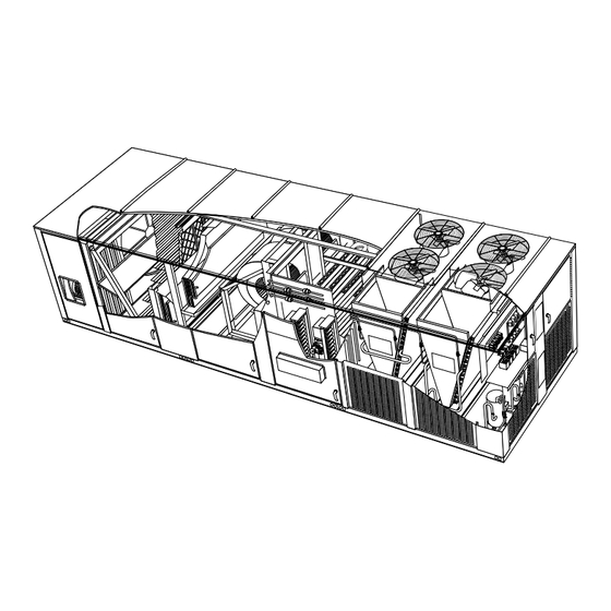
Page 43: Parts Arrangement
LGH/LCH PARTS ARRANGEMENT HEAT RECOVERY WHEEL (optional) ECONOMIZER FILTERS (optional) (eleven 16 x 25 x 2" OR 16 x 25 x 4" BLOWERS OUTDOOR FANS (6) POWER EXHAUST DISCHARGE (optional) HUMIDITROL COIL (optional) CONDENSATE EVAPORATOR DRAIN COIL FILTER DRIER BURNERS... - Page 44 LGH/LCH CONTROL BOX PARTS ARRANGEMENT K150 TB13 K152 K149 K153 TB47 K207 K203 TB24 TB40 TB41 K210 K244 TB18 DL43 K199 K201 TB19 A133 A133 TB22 K146 K201 - CONTACTOR EXHAUST BLOWER 2 TB24 - TERMINAL STRIP COMMON A55 - UNIT CONTROLLER...
-
Page 45: I-Unit Components
TB18 is also used to pass an analog signal from A34 transducer (if LGH/LCH units are configure to order units (CTO). All units used) to the A133 board. T18 also supplies an analog out... - Page 46 Several different printed cir All LGH units have two burner controls. A3 controls gas heat cuit boards (see figure 4) make‐up the modular section one, while A12 controls gas heat section two. The configurations for the LGH/LCH units.
-
Page 47: Controller Inputs And Outputs
CONTROLLER INPUTS AND OUTPUTS COMPRESSOR HEAT SECTION SAFETY INPUTS SAFETY INPUTS P262 P263 P264 P265 P266 P267 P118 P268 (1) A133 (2) A133 P269 P271 P272 P194 P194 P270 P119 P297 P298 P299 THERMOSTAT SENSOR INPUTS A133 P196 A55 (M2-0) (1)A133 (2)A133 TB18... - Page 48 LGH/LCH CONDENSER PLUMBING (shown with reheat plumbing) Condenser Coils Driers Compressors Re-Heat Valve Reheat Plumbing COMPRESSOR DETAIL Discharge Line High Pressure Switch S4, S7, S28, S96 Suction Line Gauge Port Low Pressure Switch S87, S88, S97, S98 Service Valve Gauge Port...
-
Page 49: Constant Air Volume
LGH/LCH EVAPORATOR PLUMBING constant air volume Face Split Coil Evaporator Coil Face Split Coil circuit 1 and 2 Evaporator Coil circuit 3 and 4 Re-Heat Coil (optional) Re-Heat Coil (optional) FIGURE 6 Page 49... -
Page 50: Variable Air Volume
LGH/LCH EVAPORATOR PLUMBING variable air volume Row Split Coil Row Split Coil Evaporator Coil Evaporator Coil circuit 1 and 3 circuit 2 and 4 Expansion Valve (typical) Sensing Bulb (typical) FIGURE 7 Page 50... -
Page 51: Specifications
Additional protection is provided by low ambient switches liquid line prior to the indoor coil section. and freezestats (on each evaporator). In the LGH/LCH units S11 (compressor one), S84 (com pressor two) are wired in parallel, to the outdoor fan relay 1-Compressors B1, B2, B13 & B20... -
Page 52: Condenser Fans
See Specifications section in this manual for specifica tat) located on the return bend of each evaporator coil. S49 tions of condenser fans used in LGH/LCH units. All units (first circuit), S50 (second circuit), S53 (third circuit) and are equipped with six condenser fans. The complete fan S95 (fourth circuit) are located on the corresponding assembly may be removed for servicing and cleaning. - Page 53 Condenser Fan Removal and Operation ORIFICE RING CONDENSER FAN GRILL CONDENSER FAN MOTOR CONDENSER FAN 1 1/2 3/16 ± 1/32 FAN AND RAIN SHIELD LOCATION Description Symbol Fan energized when liquid pressure is higher than 450 psig R-410A De-energized when liquid line pressure less than 240 psig R-410A.
-
Page 54: Operation / Adjustment
C-Blower Compartment Loosen both Allen screws on units equipped with two belts. Remove the key and turn the inner sheave the op The blower compartment in all units is located between the posite direction of the outer sheave. Replace the key evaporator coil and the heat section. -
Page 55: Blower Assembly
BLOWER ASSEMBLY UPPER ADJUSTMENT LOCKWASHER LOWER ADJUSTMENT TO LOOSEN BELT TO TIGHTEN BELT Turn upper nut on both ad Turn lower nuts on both justment bolts counter adjustment bolts clock clockwise. Secure support wise. Secure support plate with lower nuts. plate with upper nuts. -
Page 56: Pulley Alignment
Blower Belt Adjustment Check Belt Tension Overtensioning belts shortens belt and bearing life. Check Maximum life and wear can be obtained from belts only if belt tension as follows: proper pulley alignment and belt tension are maintained. 1- Measure span length X. See figure 13. Tighten belt as shown in figure 10.Tension new belts after a 2- Apply perpendicular force to center of span (X) with 24-48 hour period of operation. - Page 57 LGH HEATING PARTS ARRANGEMENT (high heat 11 burner, tube & standard heat 7 burner, tube) HEAT EXCHANGER BURNER MANIFOLD ASSEMBLY ROLLOUT SWITCH COLLECTOR BOX PROVE SWITCH GAS VALVE COMBUSTION AIR INDUCER ROLLOUT SWITCH BURNER MANIFOLD ASSEMBLY HEAT EXCHANGER GAS VALVE...
-
Page 58: Gas Heat Components
NOTE - Care should be taken to insure flexible pipe does not touch any other part of the unit. Breaks or tears in the flexible pipe will result in a gas leak. LGH HEAT SECTION CAI Transformer Combustion Air Relay... - Page 59 Flame rectification sensing is used on all LGH units. WARNING Loss of flame during a heating cycle is indicated by an ab sence of flame signal (0 microamps). If this happens, the con SHOCK HAZARD. SPARK RELATED COMPONENTS trol will immediately restart the ignition sequence and then lock CONTAIN HIGH VOLTAGE WHICH CAN CAUSE out if ignition is not gained after the third trial.
- Page 60 3-Combustion Air Inducer Relay K19 UTEC IGNITION CONTROL Combustion air inducer relay K19, used in all LGH units, is a DPDT relay with a 24 VAC coil. K19 is energized by the A55 Unit Controller after a standard heat demand from the ther...
-
Page 61: Burner Assembly
8-Burner Assembly (Figure 14) Btu Capacity The burners are controlled by the spark electrode, flame Standard open 140° + 5° 500,000 close 110 + 8° sensing electrode, gas valve and combustion air blower. The open 185° + 5° spark electrode, flame sensing electrode and gas valve are close 145°... - Page 62 14-Combustion Air Motor Capacitors C3 & C11 The combustion air prove switch S18 and S45 are SPST The combustion air inducer motors in all LGH units re quire run capacitors. Capacitor C3 is connected to com N.O. pressure switches located in the heat section (see fig...
-
Page 63: Flame Sensors
17-Flame Sensors WHITE-RODGERS 36C GAS VALVE A flame sensor is located on the top end of each burner SECOND STAGE support. The sensor is mounted through a hole in the burner ADJUSTMENT support and the tip protrudes into the flame envelope of the INLET right most burner. -
Page 64: Electric Heat Components
E-ELECTRIC HEAT COMPONENTS All contactors are equipped with a 24VAC coil. The coils in the K15, K16 and K17 contactors are energized by A55 Unit See ELECTRIC HEAT DATA tables (table of contents) for pos Controller. Contactors K15 and K16 energize the first stage sible LCH to EHA match-ups and electrical ratings. -
Page 65: Ii-Placement And Installation
5-Secondary Limits S20, S157, S158, S159, III-START UP - OPERATION S160 and S161 IMPORTANT-The crankcase heater must be energized for 24 hours before attempting to start compressor. Set thermostat S20, S157, S158, S159, S160 and S161 are manual reset so there is no demand to prevent compressors from cycling. limit switches that provide back up high temperature protec... - Page 66 REFRIGERANT CIRCUITS - UNITS EQUIPPED WITH CAV SUPPLY AIR BLOWERS EVAPORATOR COILS (FACE SPLIT) CONDENSER COILS COMPRESSORS 1 Refrigerant circuit 1 2 Refrigerant circuit 2 3 Refrigerant circuit 3 4 Refrigerant circuit 4 FIGURE 23 REFRIGERANT CIRCUITS - UNITS EQUIPPED WITH VFD SUPPLY AIR BLOWERS EVAPORATOR COILS (ROW SPLIT)
-
Page 67: Charging
C-Refrigerant Charge and Check TABLE 6 LGH/LCH420S - R410A - VFD WARNING-Do not exceed nameplate charge under any condition. Circuit 1 Circuit 2 Circuit 3 Circuit 4 Outdoor Coil En This unit is factory charged and should require no further Dis. - Page 68 TABLE 11 TABLE 16 LGH/LCH480H - R410A - CAV LGH/LCH600S - R410A - VFD Circuit 1 Circuit 2 Circuit 3 Circuit 4 Circuit 1 Circuit 2 Circuit 3 Circuit 4 Outdoor Outdoor Coil En Coil En tering Air tering Air...
-
Page 69: Heating Start Up
E-Heating Start Up Placing Unit In Operation WARNING FOR YOUR SAFETY READ BEFORE LIGHTING Danger of explosion and fire. Can cause BEFORE LIGHTING smell all around the appliance area for injury or product or property damage. gas. Be sure to smell next to the floor because some gas is You must follow these instructions heavier than air and will settle on the floor. -
Page 70: Safety Or Emergency Shutdown
8- Close or replace the heat section access panel. Turning Off Gas to Unit 9- Turn on all electrical power to unit. 1- If using an electromechanical thermostat, set to the lowest setting. 10- Set thermostat to desired setting. 2- Before performing any service, turn off all electrical 11- The combustion air inducer will start. -
Page 71: Iv-System Service Checks
When testing gas supply pressure, connect test gauge to the inlet pressure tap on the gas valve (figure 25 and 26). Test sup All LGH units are C.G.A. design certified without modifi ply gas pressure with unit firing at maximum rate (both cation. -
Page 72: Proper Gas Flow
Manifold Adjustment Procedure 1- Connect test gauge to the outlet pressure tap on the gas valve. Start the unit (call for second stage heat) and allow five minutes for the unit to reach steady state. 2- While waiting for the unit to stabilize, notice the flame. -
Page 73: Cooling System Service Checks
1- Disconnect power to unit. Units equipped with optional outdoor air intake hoods con tain four 20 X 25 X 2" (508 X 635 X 51mm) aluminum clean 2- Remove lead from sensing electrode and install a able filters. See figure 30 for location of filters. On horizontal 0-50DC microamp meter in series between the sens... -
Page 74: Supply Air Blower Wheel
FILTER ACCESS HORIZONTAL DISCHARGE OUTDOOR AIR HOOD SCREEN HOOD REMOVE TWO SCREWS TO ACCESS FILTERS SCREEN FIGURE 31 NOTE-If owner complains of insufficient cooling, the unit CAUTION should be gauged and refrigerant charge checked. Re fer to Gauge Manifold Attachment and Charging sec Be careful when servicing unit to avoid accidental tions in this manual. -
Page 75: Flue Box
Clean combustion air inducer as follows: I-Flue Passageway and Flue Box 1- Shut off power supply and gas to unit. 1- Remove combustion air inducer assembly as de 2- Disconnect prove switch air tubing from combustion air scribed in section H-. inducer port. -
Page 76: Vi-Accessories
LGH/LCH units. UNIT BASE RAIL A- S1CURB Mounting Frame When installing the LGH/LCH units on a combustible surface , FIBERGLASS INSULATION the S1CURB roof mounting frame is used. The roof mounting (Furnished) frames are recommended in all other applications but not re... -
Page 77: Outdoor Air Dampers
25 percent outside air into the system at all times . Either air 2- Rotate MIN POS SET potentiometer to approximate damper can be installed in LGH/LCH units. Washable filter desired fresh air percentage. Indicator on damper mo supplied with the outdoor air dampers can be cleaned with tor reads actual damper position in degrees open. - Page 78 ECONOMIZER SETTINGS LED FLASHING GREEN “HEARTBEAT" LED STEADY YELLOW “OUT A FLASHING YELLOW INDICATES NORMAL DOOR AIR SUITABLE" LED OAS LED INDICATES THE OPERATION INDICATES OUTDOOR AIR IS IAQ SENSOR IS REQUEST SUITABLE FOR COOLING ING MORE FRESH AIR DIP SWITCH SET IN TMP, ODE, DIF OR GLO MODE TMP GLO...
-
Page 79: Variable Frequency Drive (Vav)
0.55 (VAV units only) 4250 0.59 4500 0.62 LGH/LCH VAV units will contain a supply air blower 4750 0.66 equipped with a variable frequency drive A96 (VFD) which 5000 0.69 varies supply air CFM. As duct static increases, the supply 5250 0.73... -
Page 80: Gravity Exhaust Dampers
VFD (A96) and are optional with an economizer. F-Power Exhaust Blowers & Fans OUTDOOR Power exhaust blowers and fans are used with LGH /LCH se SECTION ries units. Power exhaust blowers and fans provide exhaust air pressure relief. LGH/LCH units may contain one or two power exhaust fans or blowers. - Page 81 General Purpose GP1 Board (1)A133 W/TB18 Power Exhaust Control Options Damper Position The GP1 board is positioned on the A55 Unit Controller in The Unit Controller will initiate stage 1 power exhaust when the control box area. See figure 42. Only one GP1 board is economizer or outdoor air damper travel reaches 50%.
-
Page 82: Control Systems
AIR KIT ON UNIT I-Energy Recovery Wheel LGH/LCH units may contain an optional energy recovery wheel. The ERW is located in the outdoor air entering and exhaust air streams. In the heating mode, the wheel rotates... -
Page 83: Blower Proving Switch
ERW should operate on unit start-up unless the outdoor N-Factory-Installed Humiditrol temperature is between 40°F and 65°F. When outdoor air General temperature is between 40°F and 65°F, install a jumper be Humiditrol units provide a dehumidifying mode of opera tween S125 thermostat terminal “R" and K94 relay coil ter tion. - Page 84 REHEAT MODE REFRIGERANT ROUTING EVAPORATOR NOTE COILS REHEAT Circuit 1 and Circuit 2 are similar. COILS Circuit 3 and Circuit 4 are similar. CONDENSER COILS COMPRESSORS Reheat Circuit FIGURE 47 Check-Out 4- One cooling demand is required if the unit has been in heating mode, the Unit Controller has been reset, or at Test Humiditrol operation using the following procedure.
- Page 85 TABLE 21 REHEAT OPERATION Two-Stage Thermostat - Default Operation T'stat and Humidity Demands Compressors Reheat Only Compressor 1 & 2 Reheat Compressor 1 & 2 Reheat and Reheat & Y1 Compressor 3 & 4 Cooling Reheat &Y1 & Y2 Compressor 1, 2, 3 & 4 Cooling Three-Stage Thermostat (Transfer relay required) Operation T'stat and Humidity Demands...
-
Page 86: Modulating Gas Valve
O-Modulating Gas Valve (MGV) MODULATING GAS VALVE (MGV) TO RIGHT HEAT SECTION RIGHT HEAT SECTION MODULATING TO LEFT HEAT GAS VALVE SECTION MANIFOLD PRESSURE PORT LEFT HEAT SECTION MODULATING RIGHT HEAT GAS VALVE SECTION GAS VALVE LEFT HEAT SECTION GAS VALVE MANIFOLD PRESSURE... -
Page 87: Outdoor Air Cfm Control
P-Outdoor Air CFM Control NOTE - Refer to local codes or authorities having jurisdic tion when determining design minimum outdoor air require Outdoor air CFM Control is a factory-installed option avail ments. able on units equipped with a supply air variable frequency drive (VFD) and economizer. -
Page 88: Hot Gas Bypass
1- Measure the DC voltage between TB22-6 and MANUAL DAMPER SET DIP SWITCH TB22-10. OPEN DSET 2- Multiply DC voltage by 25.4. (Damper Set) 3- Round to the nearest whole number and enter the result in ECTO 9.02. Velocity Sensor Range MIN POS The velocity sensor is factory-set for 0-5m/s. -
Page 89: Refrigerant Circuit
HOT GAS BYPASS (HGB) PIPING - REFRIGERANT CIRCUIT 1 ONLY FROM LIQUID LINE DE-SUPERHEATING TXV HGB valve starts to open SERVICE when suction pressure drops VALVE below 105psig or (34°F evap orator temperature. HOT GAS BYPASS (HGB) VALVE FROM DISCHARGE LINE SUCTION LINE... -
Page 90: Vii-Wiring Diagrams / Operation Sequence
VII-WIRING DIAGRAMS AND OPERATION SEQUENCE 24V POWER DI 1 DI 2 AI 1 AI 2 AI 3 AI 4 − − AO 1 AO 2 DI 4 A137 24V COMMON EQUIP GROUND A137 L1 L2 L3 L1 L2 L3 L1 L2 L3 L1 L2 L3 L1 L2 L3 L1 L2 L3... - Page 91 P119 USED REFER TO SECTION C DIAGRAM FUSE, COMPRESSOR GROUP 1 PLUG, INVERTER EXHAUST BLOWER P211 PLUG, I/O FOR A133 LENNOX A133 BOARD A34 SENSOR AND A137 INVERTER FUSE, COMPRESSOR GROUP 2 P194 CONTROL FOR B35 AND B36 EXHAUST AIR...
- Page 92 SEQUENCE OF OPERATION - M2-0 UNIT CONTROLLER Power: 1- Line voltage from TB13, unit disconnect S48, or other factory or field installed 2nd Stage Cooling optional power disconnects, such as CB10, energizes transformer T1 and T18. 14- Second stage cooling demand energizes Y2. Transformer T1 provides 24VAC power to terminal strip TB26 and T18 provides 15-24VAC is routed through TB18 to compressor 3 and 4 module A59.
- Page 93 24V POWER DI 1 DI 2 AI 1 AI 2 AI 3 AI 4 − − AO 1 AO 2 DI 4 A137 24V COMMON EQUIP GROUND A137 L1 L2 L3 L1 L2 L3 L1 L2 L3 L1 L2 L3 L1 L2 L3 L1 L2 L3 R S T...
- Page 94 SEQUENCE OF OPERATION - M2-1 UNIT CONTROLLER Power: 1- Line voltage from TB2, unit disconnect S48, or other factory or field installed 2nd Stage Cooling optional power disconnects, such as CB10, energizes transformer T1 and T18. 11- Second stage cooling demand energizes Y2. Transformer T1 provides 24VAC power to A55 Unit Controller and T18 pro...
-
Page 95: Gas Heat
TSTAT, OPEN −20F, CLOSE 10F TSTAT, OPEN 20F, CLOSE −10F HEATING TSTAT, OPEN 50F, CLOSE 20F SWITCH, FLAME ROLLOUT 2 SWITCH, LIMIT PRIMARY BURNER 2 TRANSFORMER, COMB AIR BLOWER 1 TRANSFORMER, COMB AIR BLOWER 2 TERMINAL STRIP, EXHAUST FANS TB47 Lennox Commercial Page 95... - Page 96 SEQUENCE OF OPERATION GAS HEAT FOR “S“ SERIES FIRST STAGE HEAT: SECOND STAGE HEAT: 8 - With first stage heat operating, an additional 1 - Heating demand initiates at W1 in thermostat. heating demand initiates W2 in the thermostat. 2 - 24VAC is routed to the A55 Unit Controller. Af 9 - A second stage heating demand is received by ter A55 proves N.C.
-
Page 97: Thermostat
PLUG, RT6 SUPPLY AIR SENSOR P100 PLUG, SMOKE DETECTOR ONE P250 PLUG, SMOKE DETECTOR ONE P251 PLUG, SMOKE DETECTOR TWO P252 PLUG, SMOKE DETECTOR TWO P253 REV. 3.0 PLUG, MODULE, CONTROL SMOKE DETECTION P255 PLUG, ECONOMIZER P262 Lennox Commercial Page 97... -
Page 98: Sequence Of Operation
SEQUENCE OF OPERATION 1 - Terminal block P297 on the A55 Unit Controller energizes the thermostat components with 24VAC. OPERATION: 2 - The A55 Unit Controller proves the optional N.O. filter switch S27(indicates dirty filter when closed) and optional N.O. air flow switch S52(indicates no air [i.e. broken belt] system shuts down). 3 - The A55 Unit Controller receives data from the supply and return smoke detectors A171 and A172, blower motor overload relay S42, discharge sensor RT6, return air sensor RT16 and the outdoor air sensor RT17. -
Page 99: Eha
EHA-30kW, 45kW, 60kW, 75kW, 90kW Y Voltage DESCRIPTION DESCRIPTION PANEL, MAIN BOARD LENNOX S99 − NC FUSE, ELECTRIC HEAT 1, 2 FUSE, ELECTRIC HEAT 3,4 S99 − NO FUSE, ELECTRIC HEAT 5, 6 S100 − C FUSE, ELECTRIC HEAT 7, 8 FUSE, ELECTRIC HEAT 9, 10 S100−NC... - Page 100 EHA-30kW, 45kW, 60kW, 75kW, 90kW, 105kW, 120kW, 150kW, 165kW & 180kW G & J Voltage DESCRIPTION DESCRIPTION PANEL, MAIN BOARD LENNOX FUSE, ELECTRIC HEAT 1, 2 S99 − NC FUSE, ELECTRIC HEAT 3,4 S99 − NO FUSE, ELECTRIC HEAT 5, 6 S100 −...
-
Page 101: Heating Elements
SEQUENCE OF OPERATION HEATING ELEMENTS: 1 - Terminal strip TB2 (CB10 or S48 may be in place of TB2) supplies line power to TB3. TB3 supplies line voltage to the heating element terminal strips. Each element is protected by a fuse and secondary limit. EHA Y VOLTAGE FIRST STAGE HEAT: SECOND STAGE HEAT:...
Need help?
Do you have a question about the LGH and is the answer not in the manual?
Questions and answers