Lennox LGH092H Installation Instructions Manual
Hide thumbs
Also See for LGH092H:
- Installation instructions manual (48 pages) ,
- Unit information (92 pages)
Table of Contents
Advertisement
Litho U.S.A.
2015
WARNING
Improper installation, adjustment, alteration, ser
vice or maintenance can cause property damage,
personal injury or loss of life. Installation and ser
vice must be performed by a licensed professional
HVAC installer or equivalent, service agency, or the
gas supplier
CAUTION
Danger of sharp metallic edges. Can cause injury.
Take care and wear protective clothing when
servicing unit to avoid accidental contact with
sharp edges.
Table Of Contents
. . . . . . . . . . . . . . . . . . . . . . . . . . . . . . . . .
. . . . . . . . . . . . . . . . . . . . . . . . .
. . . . . . . . . . . . . . . . . . . .
. . . . . . . . . . . . . . . . . . . . . . . . . . . . . . . . . . . .
. . . . . . . . . . . . . . . . . . . . . . . . . . . . . . . . . . . . .
. . . . . . . . . . . . . . . . . . . . . . . . . . . . . . . .
. . . . . . . . . . . . . . . . . . . . . . . . . . . .
. . . . . . . . . . . . . . . . . . . . . . .
. . . . . . . . . . . . . . . . . . . . . . . . . .
. . . . . . . . . . . . . . . . . . . . . . . . . . . . . . . . .
. . . . . . . . . . . . . . . . . . . . .
. . . . . . . . . . . . . . . . . . . . . . . . .
. . . . . . . . . . . . . . . . . . . . . . .
RETAIN THESE INSTRUCTIONS FOR FUTURE REFERENCE
Page 2
Page 4
Page 5
Page 5
Page 5
Page 6
Page 7
Page 7
Page 7
Page 9
Page 10
Page 11
Page 11
. . . . . . . . . . . .
Page 14
INSTALLATION
INSTRUCTIONS
LGH092H, LCH092H
LGH094U, LCH094U
LGH102H, LCH102H
LGH120H, LCH120H
LGH122U, LCH122U
LGH150S, LCH150S
LGH152U, LCH152U
PACKAGED UNITS
507245-02
9/2015
Supersedes 507245-01
. . . . . . . . . . . . . . . . . . . . . . . . . . . .
. . . . . . . . . . . . . . . . . . . . . . . . . . .
. . . . . . . . . . . . . . . . . . . . . . . .
. . . . . . . . . . . . . . . . . . . . . . . . .
. . . . . . . . . . . . . . . . . . . . . . . . . . . . . . . . . . . .
LGH SHOWN
(7.5 Ton)
(7.5 Ton)
(8.5 Ton)
(10 Ton)
(10 Ton)
(12.5 Ton)
(12.5 Ton)
Page 22
Page 34
. . . . . . . . . . . .
Page 35
Page 35
. . . . . . . . . . . . . . . . . . .
Page 36
. . .
Page 38
Page 38
. . . . . . . .
Page 40
Page 41
. . . . . . . . . . . . .
Page 45
Advertisement
Table of Contents

Related Manuals for Lennox LGH092H


Summary of Contents for Lennox LGH092H
-
Page 1: Table Of Contents
INSTALLATION Litho U.S.A. INSTRUCTIONS 2015 WARNING LGH092H, LCH092H (7.5 Ton) Improper installation, adjustment, alteration, ser LGH094U, LCH094U vice or maintenance can cause property damage, (7.5 Ton) personal injury or loss of life. Installation and ser LGH102H, LCH102H vice must be performed by a licensed professional (8.5 Ton) -
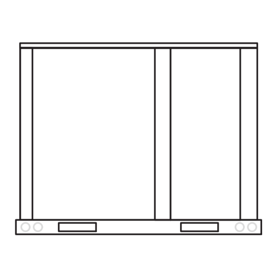
Page 2: Dimensions
LGH/LCH092, 102, 120, & 150 DIMENSIONS - GAS HEAT SECTION SHOWN 6-1/8 5-5/8 BOTTOM SUPPLY (156) (143) AIR OPENING 6-1/8 10-3/4 (156) (610) (711) (273) (508) (686) CENTER OF 60-1/8 (1527) GRAVITY BASE BOTTOM RETURN BOTTOM AIR OPENING POWER ENTRY 5-1/2 (140) Dia. - Page 3 LGH/LCH094, 122, & 152 DIMENSIONS - GAS HEAT SECTION SHOWN 6-1/8 5-5/8 BOTTOM SUPPLY (156) (143) AIR OPENING 6-1/8 10-3/4 (156) (610) (711) (273) (508) (686) CENTER OF 60-1/8 (1527) GRAVITY BASE BOTTOM BOTTOM RETURN AIR OPENING POWER ENTRY 5-1/2 (140) Diameter 6-5/8 7 (178)
-
Page 4: Parts Arrangements
LGH092, 094, 102, 120, 122, 150 & 152 PARTS ARRANGEMENT CONDENSER FANS BLOWER MOTOR DISCONNECT / EVAPORATOR (2 FANS ON 092, 102, 120, (BELT DRIVE CIRCUIT BREAKER COIL 150 UNITS; 3 FANS ON SHOWN) (FACTORY OR FIELD 094, 122, 152 UNITS) INSTALLED OPTION) UNIT CONDENSER... -
Page 5: Shipping And Packing List
Shipping and Packing List Safety Package 1 of 1 contains: See table 1 for unit clearances. 1- Assembled unit IMPORTANT - Hot gas reheat units require a specific WARNING field-provided and installed humidity sensor. Check unit for shipping damage. Receiving party should Electric shock hazard and danger of contact last carrier immediately if shipping damage is found. -
Page 6: Unit Support
Unit Support NOTICE In downflow discharge installations, install the unit on a Roof Damage! non-combustible surface only. Unit may be installed on This system contains both refrigerant and oil. combustible surfaces when used in horizontal discharge Some rubber roofing material may absorb oil, applications or in downflow discharge applications when causing the rubber to swell. -
Page 7: Duct Connection
B-Horizontal Discharge Applications A trap must be installed between drain connection and an open vent for proper condensate removal. See figure 3 or 1- Units installed in horizontal airflow applications must 4. It is sometimes acceptable to drain condensate onto use a horizontal conversion kit K1HECK00. - Page 8 2- Remove six screws from filter access door. Refer to CONDENSATE BOTTOM DRAIN CONNECTION figure 6. UNITS WITH HINGED PANELS UNIT FILTER DOOR CONDENSATE DRAIN PAN DRAIN MULLION CAULK AROUND CONDENSATE COUPLING REMOVE OPEN VENT THREE SCREWS (PER HINGE) MOUNTING FIGURE 6 FRAME 3- Open filter access door hinges and carefully remove...
-
Page 9: Gas Piping
Bottom Drain Connection Connect Gas Piping (Gas Units) 1- Open blower and heat access doors. See figure 5. 2- Remove six screws from filter access door. Refer to Before connecting piping, check with gas company or figure 6. authorities having jurisdiction local code... -
Page 10: Pressure Test Gas Piping
Pressure Test Gas Piping (Gas Units) BOTTOM ENTRY GAS PIPING THROUGH THE CURB When pressure testing gas lines, the gas valve must MULLION BETWEEN be disconnected and isolated. Gas valves can be HEAT AND COMPRES damaged if subjected to more than 0.5 psig (3.48kPa). SOR SECTIONS See figure 12. -
Page 11: High Altitude Derate
CONTROL WIRING High Altitude Derate Locate the high altitude conversion sticker in the unit CAUTION literature bag. Fill out the conversion sticker and affix next Electrostatic discharge can affect electronic com to the unit nameplate. ponents. Take precautions during unit installation Refer to table 2 for high altitude adjustments. - Page 12 2- Install thermostat assembly in accordance with be used to initiate dehumidification instead of a instructions provided with thermostat. sensor. 2- Make wiring connections as shown in figure 14 for 3- Connect thermostat wiring to the bottom of the Unit thermostat mode or figure 13 for room sensor Controller.
- Page 13 Connect both cable shield drain wires to the Unit Controller as shown in figure 15. Wire runs over 150 feet (mm): Use a local, isolated 24VAC transformer such as Lennox DO-1 cat #18M13 (20VA minimum) to supply power to RH sensor as shown in figure 16.
-
Page 14: Blower Operation And Adjustments
A-Blower Operation Blower Operation and Adjustments Note - On units with staged blowers, use the Unit Controller to start the blower. Refer to the appropriate Belt Drive With Supply Air Inverter or Direct Drive start-up section. Units - The blower rotation will always be correct on units Initiate blower only (G) demand at thermostat according to instructions provided with thermostat. - Page 15 BELT DRIVE BLOWER ASSEMBLY TO INCREASE BELT TENSION SIDE VIEW 1- Loosen four bolts securing motor mounting base to frame. 2- Turn adjusting bolt to the right, or clockwise, to move the motor away from the blower housing. MOTOR ALLEN SCREW IMPORTANT - Gap between end of frame and motor mounting base should be equal at both ends, i.e.
- Page 16 DIRECT DRIVE BLOWER ASSEMBLY BLOWER HOUSING BLOWER MOTOR SECURED TO THIS SIDE OF HOUSING REMOVE TWO SCREWS ON EACH SIDE TO SLIDE BLOWER OUT OF UNIT INLET GRID FIGURE 20 C-Determining Unit CFM 3- Referring to pages 19 through 22, use static pressure and RPM readings to determine unit CFM.
- Page 17 LOCATION OF STATIC PRESSURE READINGS INSTALLATIONS WITH DUCTWORK INSTALLATIONS WITH CEILING DIFFUSERS ROOFTOP UNIT ROOFTOP UNIT RETURN AIR READING LOCATION RETURN AIR READING RE RE SUPPLY SUPPLY LOCATION TURN TURN FIRST BRANCH OFF OF MAIN RUN MAIN DUCT RUN SUPPLY AIR SUPPLY AIR READING READING...
-
Page 18: Blower Data
BLOWER DATA 092, 094 AND 102 BELT DRIVE BLOWER − BASE UNIT BLOWER TABLE INCLUDES RESISTANCE FOR BASE UNIT ONLY (NO HEAT SECTION) WITH DRY INDOOR COIL AND AIR FILTERS IN PLACE. FOR ALL UNITS ADD: 1 − Wet indoor coil air resistance of selected unit. 2 −... - Page 19 BLOWER DATA 120, 122, 150 AND 152 BELT DRIVE BLOWER − BASE UNIT BLOWER TABLE INCLUDES RESISTANCE FOR BASE UNIT ONLY (NO HEAT SECTION) WITH DRY INDOOR COIL AND AIR FILTERS IN PLACE. FOR ALL UNITS ADD: 1 − Wet indoor coil air resistance of selected unit. 2 −...
- Page 20 BLOWER DATA 094, 122 AND 152 DIRECT DRIVE BLOWER ALL MODELS − BASE UNIT BLOWER TABLE INCLUDES RESISTANCE FOR BASE UNIT ONLY (NO HEAT SECTION) WITH DRY INDOOR COIL AND AIR FILTERS IN PLACE. FOR ALL UNITS ADD: 1 − Wet indoor coil air resistance of selected unit. 2 −...
- Page 21 BLOWER DATA FACTORY INSTALLED BELT DRIVE KIT SPECIFICATIONS Motor Efficiency Nominal hp Maximum hp Drive Kit Number RPM Range Standard & High 590 - 890 Standard & High 800 - 1105 Standard & High 795 - 1195 Standard 3.45 730 - 970 Standard 3.45 940 - 1200...
-
Page 22: Cooling Start-Up
TABLE 4 MANUFACTURER'S NUMBERS - NO TENSIONER DRIVE COMPONENTS ADJUSTABLE SHEAVE FIXED SHEAVE BELT DRIVE NO. BROWNING NO. OEM PART NO. BROWNING NO. OEM PART NO. BROWNING NO. OEM PART NO. 1VP34x7/8 31K6901 AK61x1 100244-20 AX54 100245-25 1VP40x7/8 79J0301 AK59x1 31K6801 AX55 100245-26... - Page 23 will energize the economizer; a second-stage IMPORTANT demand will energize compressor 1. 3- Ultra high efficiency units have a tandem refrigerant Mineral oils are not compatible with R410A. If oil must be added, it must be a polyol ester oil. ciruit.
- Page 24 D-Refrigerant Charge and Check - All-Aluminum Coil charging curve to determine a target liquid temperature. 092H, 102H, 120H, 150S Units WARNING-Do not exceed nameplate charge under Note - Pressures are listed for sea level applications. any condition. 4- Use the same thermometer to accurately measure the This unit is factory charged and should require no further liquid temperature (in the outdoor section).
- Page 25 TABLE 6 LGH/LCH090H Normal Operating Pressures - All-Aluminum - TXV Outdoor Coil Entering Air Temperature 65 F 75 F 85 F 95 F 105 F 115 F Suct Disc Suct Disc Suct Disc Suct Disc Suct Disc Suct Disc (psig) (psig) (psig) (psig)
- Page 26 − LGH/LCH092H4 Charging Curves - All-Aluminum - TXV Circuit 1 Outdoor Temperature (°F) Circuit 2 115° 105° 95° 85° 75° 65° Suction Pressure (psig) LGH/LCH102H Charging Curves - All-Aluminum - TXV Circuit 1 Outdoor Temperature (°F) Circuit 2 115° 105° 95°...
- Page 27 LGH/LCH120H Charging Curves - All-Aluminum - TXV Outdoor Temperature (°F) Circuit 1 Circuit 2 115° 105° 95° 85° 75° 65° Suction Pressure (psig) LGH/LCH150S Charging Curves - All-Aluminum - RFC Outdoor Temperature (°F) Circuit 1 Circuit 2 115° 105° 95° 85°...
- Page 28 E-Refrigerant Charge and Check - Fin/Tube Coil & TXV TABLE 10 LGH/LCH092H Fin/Tube - TXV LGH/LCH092H, 102H, 120H, 150S CIRCUIT 1 CIRCUIT 2 WARNING-Do not exceed nameplate charge under Outdoor Dis Dis Coil any condition. Suction Suction charge charge Entering This unit is factory charged and should require no further +5 psig +5 psig...
- Page 29 TABLE 14 Charge Verification - Approach Method - AHRI Testing LGH/LCH120H Fin/Tube - TXV (Fin/Tube Coil Continued) CIRCUIT 1 CIRCUIT 2 1- Using the same thermometer, compare liquid Outdoor Dis Dis Coil temperature to outdoor ambient temperature. Suction Suction charge charge Entering +10 psig...
- Page 30 F-Refrigerant Charge and Check - Fin/Tube Coil & RFC charging curve to determine a target liquid temperature. LGH/LCH092H, 102H, 120H, 150S WARNING-Do not exceed nameplate charge under Note - Pressures are listed for sea level applications. any condition. 4- Use the same thermometer to accurately measure the This unit is factory charged and should require no further liquid temperature (in the outdoor section).
- Page 31 LGH/LCH150S Charging Curves - Fin/Tube - RFC Outdoor Temperature (°F) Circuit 1 Circuit 2 115° 105° 95° 85° 75° 65° Suction Pressure (psig) Page 31...
- Page 32 G-Refrigerant Charge and Check - Fin/Tube Coil & TXV TABLE 19 LGH/LCH094U LGH/LCH094U, 122U, 152U Outdoor Coil Discharge +10 Entering Air Suction +5 psig psig WARNING-Do not exceed nameplate charge under Temp any condition. 655 F This unit is factory charged and should require no further 755 F adjustment.
- Page 33 H-Compressor Controls Units Equipped With Two Fans - The Unit Controller de−energizes condenser fan 2 See unit wiring diagram to determine which controls are when outdoor temperature drops below 55°F (13°C). used on each unit. Fan 1 will continue to cycle with liquid pressure. 1- Units Equipped With All-Aluminum Coils - High Pressure Switch (S4, S7) Units Equipped With Three Fans -...
-
Page 34: Gas Heat Start-Up
This unit is equipped with an automatic spark ignition Gas Heat Start-Up (Gas Units) system. There is no pilot. In case of a safety shutdown, move thermostat switch to OFF and return the thermostat FOR YOUR SAFETY READ BEFORE LIGHTING switch to HEAT to reset ignition control. -
Page 35: Heating Operation And Adjustments
5- Turn gas valve switch to OFF. See figure 27. On 3- Spark ignitor energizes and gas valve solenoid Honeywell VR8305Q gas valves, turn the knob on the opens. gas valve clockwise to “OFF”. Do not force. See 4- Spark ignites gas, ignition sensor proves the flame figure 28. -
Page 36: Supply Air Inverter Start-Up
SETTINGS > RTU Options > EDIT PARAMETER > Belt Drive Supply Air Inverter Start-Up ENTER DATA ID - 9 > MIN DAMPER LOW BLOWER = X.X % A-Design Specifications Measure the intake air CFM. If the CFM is lower than the Use table 23 to fill in field-provided, design specified design specified CFM for ventilation air, use the Unit blower CFM. - Page 37 TABLE 24 TABLE 25 MINIMUM AND MAXIMUM CFM MINIMUM AND MAXIMUM CFM BELT DRIVE STD. & HIGH EFFICIENCY UNITS BELT DRIVE ULTRA HIGH EFFICIENCY BLOWERS 094U4M, 122U4M, 152U4M Gas Heat Minimum CFM Gas Heat Minimum CFM Gas Heat Airflow Unit Unit Gas Heat Size Size...
-
Page 38: Supply Air Inverter And Direct Drive Operation
Supply Air Inverter and Direct Drive Direct Drive Blower Start-Up Operation A-Set Blower Speed This is a summary of cooling operation. Refer to the sequence of operation provided in the Engineering 1- Use table 26 to fill in field-provided, design specified Handbook or Service Manual for more detail. - Page 39 The Unit Controller will calculate the “midpoint” CFM. TABLE 27 MINIMUM AND MAXIMUM CFM DIRECT DRIVE BLOWERS 094U4E, 122U4E, 152U4E Set Minimum Position 1 Gas Heat Minimum CFM Use the following menu in the Unit Controller to set “Min Unit Gas Heat Size Airflow CFM* OCP Blwr Low”...
-
Page 40: Hot Gas Reheat Operation And Start-Up
solenoid valve, L14, routes hot discharge gas from the Hot Gas Reheat Start-Up And Operation compressor to the reheat coil. Return air pulled across General the evaporator coil is cooled and dehumidified; the Hot gas reheat units provide a dehumidifying mode of reheat coil adds heat to supply air. -
Page 41: Service
L14 Reheat Coil Solenoid Valve Service When Unit Controller input (Unit Controller J298-5 or The unit should be inspected once a year by a qualified J299-8) indicates room conditions require service technician. dehumidification, L14 reheat valve is energized (Unit Controller P269-3) and refrigerant is routed to the CAUTION reheat coil. - Page 42 C-Burners (Gas Units) 5- Check the alignment of the ignitor and the sensor as shown in figure 34 and table 29. Periodically examine burner flames proper appearance during the heating season. Before each 6- Replace burners and screws securing burner. heating season examine the burners for any deposits or 7- Replace access panel.
- Page 43 IGNITOR AND SENSOR POSITION IGNITOR SENSOR TOP VIEW SIDE VIEW IGNITOR SIDE VIEW SENSOR Gas Flow Gas Flow 1-3/4” 1-3/8” (45mm) (35mm) 3/8” 13/16” BURNER BOX (10mm) (21mm) FIGURE 34 E-Flue Passageway and Flue Box (Gas Units) HEAT EXCHANGER ASSEMBLY 1- Remove combustion air inducer assembly as HEAT described in section D.
- Page 44 Clean the all-aluminum coil by spraying the coil steadily If Interlink compressor replacement is necessary, call and uniformly from top to bottom. Do not exceed 900 psi 1-800-4-LENNOX (1-800-453-6669). or a 45_ angle; nozzle must be at least 12 inches from the IMPORTANT coil face.
-
Page 45: Unit Controller Parameter Settings
TABLE 33 Factory Unit Controller Settings 580733 Units With BACnet Module (Kohl's) Settings Use the Unit Controller to adjust parameters; menu paths Use menu SETUP > NETWORK INTEGRATION. Set “BACNET” and network address. are shown in each table. Refer to the Unit Controller manual provided with each unit. - Page 46 TABLE 35 580682 LGH/LCH092H4M, 102H4M, 120H4M, 150H4M (2-Compressor) Staged Belt Drive Factory Setting Para Field meter Setting Description Note: Any changes to Smoke CFM setting must be adjusted before the other CFM settings. Use SETTINGS > RTU OPTIONS > EDIT PARAMETERS 3000 3400...
- Page 47 TABLE 37 TABLE 38 580683 580731 LGH/LCH 094U4E (2-Compressor) Staged Direct Drive Units With Automated Logic DDC (Target) Settings Para Para Factory Field Description met Field meter Setting Setting Factory Setting Description Setting Use SETTINGS > RTU OPTIONS > EDIT PARAMETERS Note: Any changes to Smoke CFM setting must be adjusted be...
- Page 48 TABLE 41 580684 LGH/LCH 122U4E (2-Compressor) Staged Direct Drive Para met Field Factory Setting Description Setting Note: Any changes to Smoke CFM setting must be adjusted before the other CFM settings. Use SETTINGS > RTU OPTIONS > EDIT PARAMETERS 4000 Blower CFM during smoke detection.
- Page 49 U = Unconfigured Single-Stage = S Dual-Stage = D [5] Network Module Unconfigured = U N = Not Installed Power Exhaust Control 4] B = BACnet Not Installed = N L = LonTalk (Lennox) Damper Position = A FIGURE 37 Page 49...
- Page 50 Installed on DI-3 = 3 [5] Phase / Voltage Detection * N = Not Installed 1 = Enabled Internal (Lennox) 2 = External (A42) Phase Detection * When Phase / Voltage detection monitoring is enabled on a three-phase on DI-2 system and configured incorrectly will result in the system going into de...
Need help?
Do you have a question about the LGH092H and is the answer not in the manual?
Questions and answers