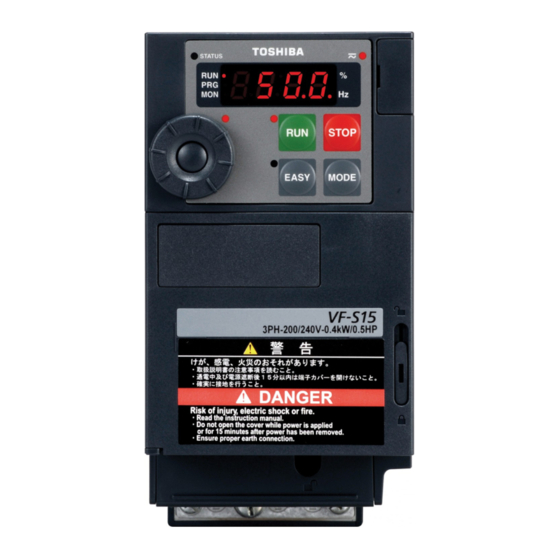
Toshiba TOSVERT VF-S15 Series Instruction Manual Supplementary
Hide thumbs
Also See for TOSVERT VF-S15 Series:
- Instruction manual (394 pages) ,
- Quick start manual (90 pages) ,
- Function manual (80 pages)
Advertisement
Quick Links
E6582185
Instruction Manual (Supplementary)
VF-S15
TOSVERT
Thank you for purchasing a Toshiba TOSVERT VF-S15 series inverter.
This instruction manual explains additional information about VFS15-400PL1 to 4037PL1.
This instruction manual gives a supplementary explanation of some items referred to in the instruction manual
E6581928(Quick Start) and E6581611(Detailed).
Please read this manual carefully along with the instruction manual E6581928 and E6581611.
3-phase 500V class
0.4 to 4.0 kW
- NOTICE -
1. Make sure that this instruction manual is delivered to the end user of the inverter unit.
2. Read this manual before installing or operating the inverter unit, and store it in a safe place for reference.
3. Please see to it that this manual is supplied to the inverter's end user, along with the instruction manual
E6581928(Quick Start).
1
Advertisement

Summary of Contents for Toshiba TOSVERT VF-S15 Series
- Page 1 Instruction Manual (Supplementary) VF-S15 TOSVERT Thank you for purchasing a Toshiba TOSVERT VF-S15 series inverter. This instruction manual explains additional information about VFS15-400PL1 to 4037PL1. This instruction manual gives a supplementary explanation of some items referred to in the instruction manual E6581928(Quick Start) and E6581611(Detailed).
-
Page 2: Contents Of The Product
E6582185 ■Safety precautions Please read “I. Safety precautions” and text in the manual E6581611 in CD-ROM. Following chapter numbers are same as the manual E6581611. Contents of the product Explanation of the name plate label Type Form V F S 1 5 - 4 0 0 7 P L 1 - W 1 Applicable motor Additional functions II Model name... - Page 3 E6582185 (1) Removing the outside terminal block cover (VFS15-4004PL1-W1 to 4037PL1-W1) 1.3.2(3)̲ 外 側端子台カバーはずし方 ̲s2f̲rev01̲01.eps Insert a screwdriver or other thin object While pressing on the screwdriver, sidles into the hole indicated with the mark. the terminal cover downward to remove it. 1.3.2(3)̲...
- Page 4 E6582185 1.3.2 Power circuit and control circuit terminal blocks Power circuit terminal VFS15-4004PL1-W1 to 4015PL1-W1 M3 screw Grounding capacitor M4 screw Shorting-bar switch position A ( ) Grounding capacitor switch position B ( ) Grounding terminal (M4 screw) For EMC plate Grounding terminal (M5 screw) VFS15-4022PL1-W1 to 4037PL1-W1 M4 screw...
- Page 5 E6582185 Grounding capacitor switch Three-phase 500V model have a built-in high-attenuation noise filter and is grounded via a capacitor. A switch screw makes for easy switching to reduce leakage current from the inverter and the load on the capacitor. However, be careful, as reducing the load means non-conformity with the EMC standard on the inverter itself.
-
Page 6: Pwm Carrier Frequency
The default setting of motor parameters are adapted to Toshiba IE3 motor. In case of using Toshiba standard IE1 motor, the parameters values should be adjusted according to Table 4 (VFS15-4004PL to 4037PL) in E6582165 (VF-S15 motor control parameter default setting update information). -
Page 7: Outside Dimensions And Mass
E6582185 12.2 Outside dimensions and mass Outside dimensions and mass Applicable Dimensions (mm) Approx. Voltage motor Inverter type Drawing weight class (kW) (kg) VFS15-4004PL1-W1 0.75 VFS15-4007PL1-W1 121.5 3-phase VFS15-4015PL1-W1 500V VFS15-4022PL1-W1 VFS15-4037PL1-W1 Outline drawing Φ5 93 (Mounting dimension) VF-S15 EMC plate (Option) Note 2) Fig. - Page 8 E6582185 2-Φ5 126 (Mounting dimension) 2-R2.5 VF-S15 EMC plate (Option) Note 2) Fig. C1 Note 1 To make it easier to grasp the dimensions of each inverter, dimensions common to all inverters in these figures are shown with numeric values but not with symbols. Here are the meanings of the symbols used.
- Page 9 E6582185 ■ UL standard and CSA standard The VF-S15 models that conform to the UL Standard and CSA Standard have the UL/CSA mark on the nameplate. This additional sheet is correction and additional information of as appendix for section 9.2 in E6581611. 2.
- Page 10 E6582185 AIC, Fuse and Wire sizes Use the UL listed fuses at connecting to power supply. Short circuit test is performed under the condition of the power supply short-circuit currents in below. These interrupting capacities and fuse rating currents depend on the applicable motor capacities. Table 3 AIC, Fuses and Wire sizes Input Output...
- Page 11 E6582185 Control circuit terminals The control circuit terminal block is common to all equipment. Electrical Terminal Input / Function specifications symbol output Note 4) Multifunction programmable relay contact output. Max. switching capacity Detects the operation of the inverter's protection 250Vac (OVC II) -2A, Output function.
- Page 12 E6582185 ■ Manufacturer’s Declaration of Conformity...
- Page 13 E6582185...
- Page 14 E6582185...
- Page 15 E6582185 © Toshiba Schneider Inverter Corporation 2017...


Need help?
Do you have a question about the TOSVERT VF-S15 Series and is the answer not in the manual?
Questions and answers