
Subscribe to Our Youtube Channel
Related Manuals for Videotec PELCO MAXIMUS MPX Series


Summary of Contents for Videotec PELCO MAXIMUS MPX Series
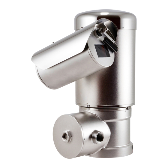
- Page 1 ENGLISH MAXIMUS MPX SERIES2 (MPXHD) MAXIMUS MPXL SERIES2 (MPXL) Flameproof PTZ camera English - Instruction manual...
-
Page 3: Table Of Contents
Contents E N G L I S H 1 About this manual ........................5 1.1 Typographical conventions ..............................5 2 Notes on copyright and information on trademarks ............5 3 Safety rules ..........................6 4 Product description and type designation ................9 4.1 Range of use ..................................... - Page 4 8 Configuration..........................25 8.1 Default IP address ................................25 8.2 Web interface ..................................25 8.2.1 First access to the web pages ................................25 9 Instructions for normal operation ..................26 9.1 Enabling the LED illuminator ............................26 10 Maintenance .........................26 10.1 Routine maintenance ...............................26 10.1.1 Inspecting the cables ..................................26 10.1.2 Replacing the gasket ..................................26 10.1.3 Replacement of the wiper blade ..............................27 10.2 Extraordinary maintenance ............................27...
-
Page 5: About This Manual
(including consequential damages) caused by reliance on the information presented herein. Underlined titles For greater certainty, the use of "manufacturer" in Information is subject to certifications. this manual means "VIDEOTEC s.r.l.". 2 Notes on copyright and 1.1 Typographical conventions information on trademarks DANGER! The mentioned names of products or companies are Explosion hazard. -
Page 6: Safety Rules
3 Safety rules • Make sure that the power is off when installing or carrying out maintenance, with the circuit-breaker open. DANGER! • A power disconnect device must be included Explosion hazard. in the electrical installation, and it must be very Read carefully to avoid danger of quickly recognizable and operated if needed. - Page 7 • This product must only be repaired by suitably trained personnel or under the supervision of VIDEOTEC personnel in accordance with the foreseen terms and conditions: IEC/EN60079-19. • Only use original VIDEOTEC. Strictly adhere to the maintenance instructions attached to each replacement kit. MNLCMPXHDC_2222_EN...
- Page 8 • Contact the manufacturer for information on the INFO dimensions of the flameproof joint. Description of system specifications. • For all maintenance interventions, we recommend We recommend reading this part carefully you return the product to the laboratory that will in order to understand the subsequent perform all required operations.
-
Page 9: Product Description And Type Designation
4 Product description and 4.2 Specific use conditions type designation Contact the manufacturer for information on the dimensions of the flameproof joint. The MAXIMUS MPX series is a range of Ambient temperature and Surface temperature – see electropolished AISI316L steel PTZ cameras that can instructions. -
Page 10: Cable Entry
4.5 Cable entry 4.5.1 Stopping plug The stopping plug supplied is not KCs The product is supplied with plastic caps for certified. cable entry protection. They cannot be used for installation. With the product, an Ex certified stopping plug Unused cable entries must be closed using is supplied with “db”... -
Page 11: Product Marking
4.6 Product marking Fig. 2 Manufacturer’s name and address. ATEX marking. The Class temperature depends on the electronics installed inside and the Model. ambient temperature. The serial number consists in 12 numeric 10. IECEx marking. The Class temperature depends characters, the second and third digits on the electronics installed inside and the define the last two numbers of the year of ambient temperature. -
Page 12: For Ul/Csa Standard Reference Only
4.7 For UL/CSA standard reference only. The flameproof joints are not intended to be repaired. CAUTION! Hazardous moving parts. Keep fingers and other body parts away. The appliance includes moving parts. Make sure that the unit is positioned where it is inaccessible under normal operating conditions. - Page 13 Fig. 5 Ambient temperature (-40°C ≤ Ta ≤+TX°C, -40°C Manufacturer’s name and address. ≤ Ta ≤ TX°C or TX°C, -40°C ≤ Ta ≤ TX°C or TX°C Model. or TX°C). The serial number consists in 12 numeric T Class (Tx or Tx...Tx). characters, the second and third digits define the last two numbers of the year of Maximum surface temperature (Tx°C or Tx°C...
-
Page 14: Model Identification
EN - English - Instruction manual 4.8 Model identification 4.8.1 Day/Night camera MAXIMUS MPX SERIES2 - CONFIGURATION OPTIONS Voltage Camera Temperature class and ambient tempe- Options rature MPXHD 230Vac Pelco® Day/Night 30X zoom, Full HD camera T6...T5 -40°C/+55°C or +70°C Without accessories 24Vac With SD CARD... -
Page 15: Day/Night Camera With Led Illuminator
4.8.2 Day/Night camera with LED illuminator MAXIMUS MPXL SERIES2 - CONFIGURATION OPTIONS Voltage Day/Night camera Illuminator Lens Temperature class and ambient temperature Accessories MPXL from 220Vac up to Pelco® camera, 850nm Spot, ATEX - IECEx - INMETRO - EAC Ex - KCs - UK Ex Without accessories 230Vac Day/Night 30X... -
Page 16: Preparing The Product For Use
5 Preparing the product for 6 Installation Before carrying out any type of maintenance, read the "Safety rules" Before carrying out any type of chapter carefully in the product manual. maintenance, read the "Safety rules" PELCO strongly recommend to test the device chapter carefully in the product manual. -
Page 17: Fixing To Parapet Or Ceiling Mount
6.1.1 Fixing to parapet or ceiling mount 6.1.2 Fixing with wall mount bracket Fix the adaptor (01) to the bottom of the unit using The bracket can be fixed to the vertical wall. Use the 4 flat countersunk screws (02) with hexagonal screws and wall fixing devices that can bear at least socket M10x20mm in stainless steel (A4 class 70) four times the weight of the unit. -
Page 18: Fixing With Corner Adaptor Module Or Pole
6.1.3 Fixing with corner adaptor 6.1.4 Sunshield mounting module or pole Remove the protective film before the To install the product on the corner adaptor module sunshield installation (if present). or pole, first of all fasten the support bracket. Apply a generous amount of thread locking compound (Loctite 270) into the threaded holes in the base of the device. -
Page 19: Opening Of The Connections Compartment
6.2 Opening of the connections 6.3 Connector board description compartment BOARD DESCRIPTION Connector Function Terminals - Nomi- The safety grub screw is used to prevent nal section of the the unscrewing of the threaded cover from cables used the connection compartment. Remove the Power supply line from 0.2mm²... -
Page 20: Ground Connection
6.4 Ground connection 6.5 Connecting the power supply Depending on the version, the device can be 6.4.1 Earthing equipotential connection provided with different power supply voltages. The The equipotential connection must be carried out power supply voltage is indicated on the product using an external cable with a minimum 4mm²... -
Page 21: Connecting Alarms, Remote Reset And Relays
6.6 Connecting alarms, remote CONNECTING THE POWER SUPPLY reset and relays Cable colour Terminals Power supply 24Vac All signal cables must be grouped together Defined by the installer ~/24Vac by means of a cable tie. Defined by the installer ~/24Vac Yellow/Green CONNECTION OF THE ALARM INPUTS AND RELAYS Power supply 100Vac, 120Vac, 220Vac, 230Vac... -
Page 22: Connecting An Alarm With Dry Contact
6.6.1 Connecting an alarm with dry 6.7.1 Connection via RJ45 contact Make connections in accordance with the Connect terminals AL1 and COM to connector J6 as TIA/EIA-568-B standard. shown in the image (Fig. 16, page 21). Connect the Ethernet cable to port RJ45 (6.3 Maximum length of the alarm cables: 200m (656ft). -
Page 23: Installations According To Ul/Csa Standards
6.8 Installations according to UL/ CSA standards Pay attention not to damage the conductors and the boards. For installations according to UL/CSA standards, the cables for Ethernet, reset, alarms, relays and fibre optics should be inserted in the right cables entry (01) as indicated in the following figure (Fig. -
Page 24: Connection Compartment Closing
The device could be no longer safe for the installation on a potentially explosive atmosphere. In this case contact VIDEOTEC technical support. Before closing the cover, check the integrity of the O-ring gasket. If the gasket is damaged, replace it with the one supplied (10.1.2 Replacing the gasket,... -
Page 25: Switching On
7 Switching on 8 Configuration 8.1 Default IP address Before carrying out any type of maintenance, read the "Safety rules" chapter carefully in the product manual. The unit is configured to obtain an IP address from a DHCP server. The automatic pre-heating (De-Ice) The IP address acquired via DHCP is visible in the process could be started whenever the DHCP server log file. -
Page 26: Instructions For Normal Operation
Before carrying out any type of chapter carefully in the product manual. maintenance, read the "Safety rules" When contacting VIDEOTEC for assistance please chapter carefully in the product manual. provide the serial number and the identification code of the model. -
Page 27: Replacement Of The Wiper Blade
10.2 Extraordinary maintenance 10.1.3 Replacement of the wiper blade In models equipped with a wiper, the worn blades 10.2.1 Fuse replacement can be replaced. Unscrew the rivet nut fastening the blade and CAUTION! To ensure protection against the remove it with the washers. Replace the worn risk of fire, replace the fuse with one the blade with a new one. -
Page 28: Factory Default
11 Cleaning 10.2.2 Factory Default If the access password is no longer Before carrying out any type of available, follow the procedure to reset to maintenance, read the "Safety rules" default factory settings. chapter carefully in the product manual. The effect of the Factory Default procedure is Frequency will depend on the type of the same as restoring the factory default settings environment in which the product is used. -
Page 29: Information On Disposal And Recycling
12 Information on disposal 13 Troubleshooting and recycling Before carrying out any type of maintenance, read the "Safety rules" The European Directive 2012/19/EU on Waste chapter carefully in the product manual. Electrical and Electronic Equipment (WEEE) mandates that these devices should not be disposed Contact an authorised support centre if of in the normal flow of municipal solid waste, but the problems persist or you have any other... -
Page 30: Technical Data
14 Technical data 14.1.4 Network RJ45 port 14.1 MAXIMUS MPX SERIES2 • Ethernet connection: 10BASE-T/100BASE-T (MPXHD) Slot SFP (SMALL FORM FACTOR PLUGGABLE) • Ethernet connection:100BASE-FX 14.1.1 General • Supply voltage: 3.3V AISI 316L stainless steel construction • Standard: MSA compliant External surfaces micro-shot peened and electro- The SFP module (not supplied by PELCO) must meet polished... -
Page 31: Video
14.1.6 Video 14.1.7 Cameras Video encoder Resolution: Full HD 1080p (1920x1080pixel) • Communication protocol: ONVIF, Profile G, Profile Image Sensor: 1/2.8" Progressive Scan CMOS S and Profile T Focal length: from 4.3mm (wide) up to 129mm (tele) • Protocols: IPv4, IPv6, HTTP, HTTPS, SOAP, DNS, Zoom: 30x NTP, RTSP, RTCP, RTP, TCP,UDP, IGMP, ICMP, DHCP, Max Aperture: F1.6... -
Page 32: Environment
14.1.8 Environment 14.1.10 Certifications - Explosion-proof applications For indoors and outdoors installation ATEX (EN IEC 60079-0, EN 60079-1, EN 60079-31) Operating temperature: IECEx (IEC 60079-0, IEC 60079-1, IEC 60079-31) • Continuous working (in enclosed space): from -40°C (-40°F) up to +55°C (131°F) UL listed for USA (UL 60079-0, UL 60079-1, UL 60079- 31) (not available for 100Vac versions) •... -
Page 33: Maximus Mpxl Series2 (Mpxl)
14.2 MAXIMUS MPXL SERIES2 14.2.4 Network (MPXL) RJ45 port • Ethernet connection: 10BASE-T/100BASE-T 14.2.1 General Slot SFP (SMALL FORM FACTOR PLUGGABLE) AISI 316L stainless steel construction • Ethernet connection:100BASE-FX External surfaces micro-shot peened and electro- • Supply voltage: 3.3V polished •... -
Page 34: Cameras
14.2.7 Cameras 14.2.8 Illuminators Resolution: Full HD 1080p (1920x1080pixel) The illuminator with IR or white LED Image Sensor: 1/2.8" Progressive Scan CMOS Number of LED groups selectable:2 (spot, wide) Focal length: from 4.3mm (wide) up to 129mm (tele) Wide beam angle of dispersion: 40° (horizontal), 16° (vertical) Zoom: 30x Spot beam angle of dispersion: 13°... -
Page 35: Certifications
14.2.10 Certifications 14.2.11 Certifications - Explosion-proof applications Electrical safety (CE): EN60950-1, IEC60950-1, EN62368-1, IEC62368-1 ATEX (EN IEC 60079-0, EN 60079-1, EN 60079-31) Electromagnetic compatibility (CE): EN50130-4, IECEx (IEC 60079-0, IEC 60079-1, IEC 60079-31) EN55032 (Class A), EN61000-6-4, EN61000-3-2, UL listed for USA (UL 60079-0, UL 60079-1, UL 60079- EN61000-3-3 31) (not available for 100Vac versions) RoHS (CE): EN IEC 63000... -
Page 36: Technical Drawings
15 Technical drawings The indicated measurements are expressed in millimetres. Fig. 26 MAXIMUS MPX SERIES2 (MPXHD). MNLCMPXHDC_2222_EN... - Page 37 Ø 138 Fig. 27 MAXIMUS MPXL SERIES2 (MPXL). MNLCMPXHDC_2222_EN...
- Page 38 Headquarters Italy VIDEOTEC s.r.l. Via Friuli, 6 - I-36015 Schio (VI) - Italy Tel. +39 0445 697411 - Fax +39 0445 697414 Email: info@videotec.com www.videotec.com MNLCMPXHDC_2222_EN...
Need help?
Do you have a question about the PELCO MAXIMUS MPX Series and is the answer not in the manual?
Questions and answers