Table of Contents
Advertisement
AC/DC
DIGITA CLAMP METER
OPERATION MANUAL
CONTENTS
1.
1.1
1.2
1.3
1.4
2.
2.1
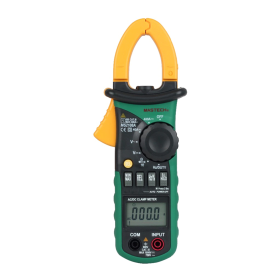
NAMES OF PARTS
2.2
2.3
3.
3.1
3.2
TECHNICAL SPECIFICATIONS
4.
4.1
4.2
4.3
4.4
4.5
4.6
4.7
4.8
4.9
4.10
......1
......1
......2
......3
......3
......4
......5
......8
......8
......10
......10
......11
......16
......16
......16
......17
......17
......18
......18
......19
......19
......20
......21
Advertisement
Table of Contents

Related Manuals for Mastech MS2108A


Summary of Contents for Mastech MS2108A
-
Page 1: Table Of Contents
CONTENTS SAFETY INFORMATION ……1 PRELIMINARY ……1 DURING USE ……2 SYMBOLS ……3 MAINTENANCE ……3 AC/DC DESCRIPTION ……4 NAMES OF PARTS ……5 DIGITA CLAMP METER SWITCH, BUTTONS AND INPUT JACKS ……8 LCD (Liquid-crystal display) ……8 SPECIFICATIONS ……10 GENERAL SPECIFICATIONS ……10 TECHNICAL SPECIFICATIONS ……11 OPERATION INSTRUCTION ……16... -
Page 2: Safety Information
CONTENTS 1. SAFETY INFORMATION 4.11 MEASURING AC VOLTAGE ……23 WARNING BE EXTREMELY CAREFUL WHEN USING THIS 4.12 MEASURING DC VOLTAGE ……24 METER. Improper use of this device can result in electric 4.13 MEASURING FREQUENCY ……26 shock or destruction of the meter. Take all normal safety 4.14 MEASURING DUTY ……29... -
Page 3: During Use
have been incurred. 1.2.10 Do not take capacitance measurements until the capacitor to be measured has been fully discharged. 1.1.4 Test leads must be kept in good condition. Before using check whether the insulation on test leads has been damaged and any 1.2.11 Do not use the meter near explosive gases, steam or dirt. -
Page 4: Description
current. Disconnect the test leads from all sources of electric function. current before opening the rear case and battery cover of the meter. - This meter is equipped with minimum value measuring function. 1.4.3 To avoid any electric shock caused by error readings, replace the batteries immediately when the “... - Page 5 - 7 - - 6 -...
-
Page 6: Switch, Buttons And Input Jacks
2.2 SWITCH, BUTTONS AND INPUT JACKS HOLD/B.L Button - For holding the reading or control backlight SEL Button - For switching among measuring functions REL Button - The key is the relative value measurement. ALTERNATING CURRENT Hz/% Button Direct current - For switching between frequency and duty measuring functions. -
Page 7: Specifications
3. SPECIFICATIONS 3.2 ELECTRICAL SPECIFICATIONS Calibration is required once a year, to be carried out at a Ambient temperature: 23±5 ℃ Relative humidity: < 75% temperature between 18°C and 28 °C (64°F to 82°F) and relative 3.2.1 AC Current humidity below 75%. Range Resolution Accuracy... - Page 8 test leads contact the circuit. This is normal because the meter is Range Resolution Accuracy highly sensitive. When the test leads contact the circuit, the true 10Hz 0.01Hz reading will be shown. 1kHz 0.001kHz ± ( 1 .5% of rdg + 5 digits )...
- Page 9 3.2.9 Continuity - Frequency response: 10 ~ 10 kHz - Input voltage range: ≥ 1 V rms AC Range Resolution Function - Input impedance: 10MΩ 0. 1Ω Built-in buzzer will sound, if - Max. input voltage: 750V rms AC resistance is lower than 40Ω. 3.2.6.3 By Hz/DUTY range - Open circuit voltage ~ 1.2V - Frequency response: 1 ~ 10MHz...
-
Page 10: Operation Instruction
4. OPERATION INSTRUCTION measurement mode, and go back to the normal mode (REL∆ will 4.1 HOLDING READINGS disappear in the LCD). 4.1.1 Press the “HOLD/B.L” button to hold the readings while 6) OL triggering: Under REL △ mode, OL shows when input value taking measurement and the value on the display will be held. -
Page 11: Switching Functions
NOTE: minimum value will be recorded by the chip. - LED which requires a larger working current, is the main source of back light. Although the meter is equipped with a timer set at 4.4.2 Press the ”MAX/MIN” button more than two second , the about 15 seconds (i.e. -
Page 12: Measuring Ac Current
4.10 MEASURING DC CURRENT 4.8.3 Turn the rotary selector to the required function and range to be measured. WARNING 4.8.4 Connect the common test lead first and then the charged test Beware of Electrocution. leads when making connection. Take away the charged test Ensure that the test leads are disconnected from the meter lead first when disconnecting. -
Page 13: Measuring Ac Voltage
4.11 MEASURING AC VOLTAGE WARNING Beware of Electrocution. Pay special attention to avoid electric shock when measuring high voltage. Do not input the voltage which more than 750V rms AC. 4.12.1 Plug the black test lead into the COM jack and the red test lead into the INPUT jack. -
Page 14: Measuring Dc Voltage
the polarity of the end connected by the red test lead. NOTE: 1) At small voltage range, unsteady readings will appear before the test leads contact the circuit. This is normal because the meter is highly sensitive. When the test leads contact the circuit, the true reading will be shown. -
Page 15: Measuring Frequency
4.13 MEASURING FREQUENCY 4.13.1 By A range (from current clamp): WARNING Beware of Electrocution. Ensure that the test leads are disconnected from the meter before making current clamp measurements. 4.13.1.1 Set the rotary selector to the A range ( A or A position. -
Page 16: Measuring Duty
4.14 MEASURING DUTY 1) Frequency test range is 10Hz -10kHz. It is possible to test the frequency which is higher than 10kHz but the tolerance of the 4.14.1 By A range ( from current clamp): test result can not be ensure. WARNING 2) “... - Page 17 4.14.2.4 Connect test leads to the two end of the source or load for measurement. 4.14.2.5 Take the reading on the LCD. NOTE: 1) If the duty cycle is less than 10%, symbol ‘UL’ will be displayed on LCD; if the duty cycle is more than 94.9%, symbol ‘OL’...
-
Page 18: Measuring Resistance
4.15 MEASURING RESISTANCE 4.14.3 By HZ/DUTY range: WARNING WARNING Beware of Electrocution. Beware of Electrocution. Pay special attention to avoid When measuring in-circuit resistance, make sure that the electric shock when measuring high voltage. Do not input power of the circuit under test has been turned off and that the voltage which more than 250V rms AC. -
Page 19: Testing Diode
4.16 TESTING DIODE 4.16.1 Plug the black test lead into the COM jack and the red test lead into the INPUT jack. 4.16.2 Set the rotary selector to the range position. 4.16.3 Press the "SEL" button to switch to test. 4.16.4 Connect the red test lead to the anode and the black test lead to the cathode of the diode for testing. -
Page 20: Testing Continuity
4.17 TESTING CONTINUITY WARNING Beware of Electrocution. Make sure that the power of the circuit has been turned off and the capacitors have been fully discharged before testing the continuity of a circuit. 4.17.1 Plug the black test lead into the COM jack and the red test lead into the INPUT jack. -
Page 21: Maintenance
lead into the INPUT jack. 5. MAINTENANCE 4.18.2 Set the rotary selector to the range position. 4.18.3 After fully discharged the capacitor, connect the test leads to 5.1 REPLACING THE BATTERIES the two ends of the capacitor for measurement. WARNING 4.18.4 Take the reading on the LCD. - Page 22 HYS006169...
Need help?
Do you have a question about the MS2108A and is the answer not in the manual?
Questions and answers