Table of Contents
Advertisement
Contents......................................................................................................................................................................................... I
Chapter 1.....................................................................................................................................................................................
Safety Standards............................................................................................................................................................................. 1
Warning......................................................................................................................................................................................... 1
Warranty......................................................................................................................................................................................... 2
Chapter 2.....................................................................................................................................................................................
Introduction and Specifications..................................................................................................................................................... 3
Front Panel..................................................................................................................................................................................... 3
Rear Panel..................................................................................................................................................................................... 7
LCD Display Description............................................................................................................................................................. 9
Function Descriptions.....................................................................................................................................................................10
Chapter 3 Operation Manual..................................................................................................................................................... 11
Understanding AC Zero Input Behavior of True RMS Meters.................................................................................................... 11
DC/AC(TRMS) Voltage................................................................................................................................................................. 11
DCmV/ACmV............................................................................................................................................................................. 13
Ohm/Continuity/DIODE.................................................................................................................................................................14
Capacitance Measurement............................................................................................................................................................. 15
Logic Frequency/Duty cycle Measurement................................................................................................................................. 16
Clamp Measurement..................................................................................................................................................................... 17
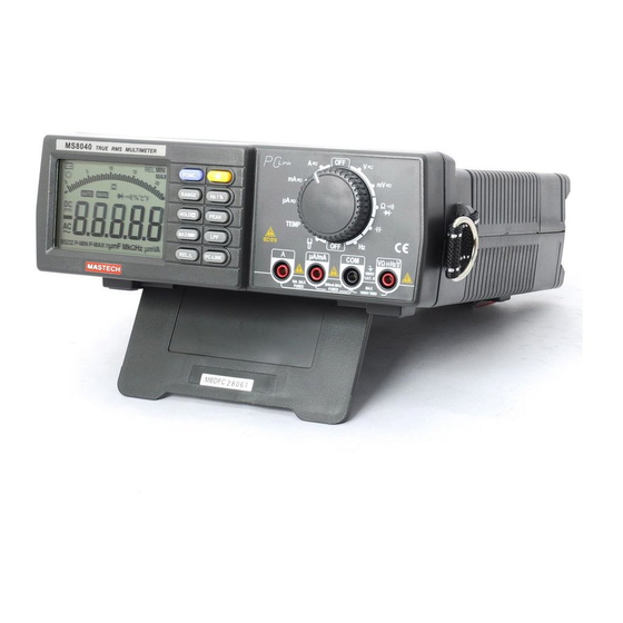
BENCH MODEL MULTIMETER
Contents
I
1
3
Advertisement
Table of Contents

Related Manuals for Mastech MS8040


Summary of Contents for Mastech MS8040
-
Page 1: Table Of Contents
BENCH MODEL MULTIMETER Contents Contents......................................I Chapter 1..................................... Safety Standards..................................... 1 Warning......................................1 Warranty......................................2 Chapter 2..................................... Introduction and Specifications..............................3 Front Panel..................................... 3 Rear Panel..................................... 7 LCD Display Description................................9 Function Descriptions..................................10 Chapter 3 Operation Manual..............................11 Understanding AC Zero Input Behavior of True RMS Meters....................11 DC/AC(TRMS) Voltage................................. - Page 2 Temperature measurement................................19 DCμA / AcμA measurement................................. 20 DC mA / AC mA measurement..............................21 DC A / AC A measurement................................22 Linear Frequency Measurement..............................23 Relative Measurement................................. 24 Max/Min Value..................................... 25 Data Hold..................................... 25 Low Passed Filter..................................25 Peak Value..................................... 26 RS232 Interface.....................................
- Page 3 BENCH MODEL MULTIMETER...
-
Page 4: Chapter 1
BENCH MODEL MULTIMETER Chapter 1 Safety Standards This style of digital multimeter is designed and manufactured according to the safety requirements set out by the IEC 61010- 1 standards for electronic test instruments . Its design and manufacture is strictly based on the provisions in the 1000V CAT II of IEC61010-1 and the Stipulation of 2-Pollution Grade. -
Page 5: Warranty
Replacing the Power Fuse Always use the power cord and connector appropriate for the voltage and outlet of the country or location in which you are working. Remove test leads from the Meter before opening the case. Never remove the cover or open the case of the Meter without first removing it from the main power source. ... -
Page 6: Chapter 2
BENCH MODEL MULTIMETER warranty does not apply to fuses, disposable batteries. Chapter 2 Introduction and Specifications 22000 Counts ACV and DCV up to 1000V 10μV Sensitivity for Voltage measurement. Linear Frequency 、 Logic Frequency and Duty Measurement ... - Page 7 Replacing the Power Fuse Front Panel Features VΩHz Terminal Input positive terminal for all measurement except current measurement , connected with red test leads. COM Terminal...
- Page 8 BENCH MODEL MULTIMETER Input common terminal for all measurement , connected with black test leads. μA/mA Terminal Input positive terminal for current measurement (μA/mA) , connected with red test lead. A Terminal Input positive terminal for current measurement (A) , connected with red test lead. Rotary Switch Switching positions correspondingly when changing different input signals.
- Page 9 Replacing the Power Fuse Name Description To activate the low passed filter function, most of noise above 1KHz will decay greatly. RELΔ LCD panel displays relative value. PC-LINK LCD panel displays ‘RS232’ , the meter communicates with PC software. FUNC button description Rotary Position Input Signal DCV ...
-
Page 10: Rear Panel
BENCH MODEL MULTIMETER Button description RANGE HOLD MAX/MI PEAK PCLINK ( N ( Note ote 1) 2 ) Voltage ○ ○ ○ ○ ○ ○ ○ ○ ○ Current ○ ○ ○ ○ ○ ○ ○ ○ Clamp ○ ○ ○... - Page 11 Replacing the Power Fuse Battery Cover Replace 9V 6F22 or 1.5×6 AA battery. Supply Power Inlet with Fuse, Houses Fuse 0.1A/250V. Power Switch RS232 Socket...
-
Page 12: Lcd Display Description
BENCH MODEL MULTIMETER LCD Display Description ( 1 ) Bargraph Display Zone ( 2 ) Digital Display Zone... - Page 13 Replacing the Power Fuse Display Annunciators and Indicators Sign Description Battery (low battery when shown on display.) Auto power off function is selected DC (Direct Current) AC (Alternating Current) Hold status is selected Diode test is selected Continuity test is selected Communication with PC terminal is selected RS232 Reading is minimum peak value...
-
Page 14: Function Descriptions
BENCH MODEL MULTIMETER Function Descriptions Auto range or manual range : Toggle to manual mode in autorange mode , increase range in manual mode ; toggle to autorange mode when pressing longer than 1 S in manual mode. Linear frequency :... -
Page 15: Dc/Ac(Trms) Voltage
Replacing the Power Fuse specified measurement range. DC/AC(TRMS) Voltage The Meter is capable of measuring voltage up to 1000 V DC and 750 V AC. To perform a voltage measurement: Turn rotary switch to position , LCD panel displays‘DC’; press FUNC button when measuring AC voltage, and LCD display ‘AC’;... -
Page 16: Dcmv/Acmv
BENCH MODEL MULTIMETER DCmV/ACmV The Meter is capable of measuring mV up to 220mV. To perform a mV measurement: Turn rotary switch to position , LCD panel displays‘DC’; press FUNC button when measuring AC mV, and LCD display ‘AC’; Connect red test lead with VΩHz terminal and black test lead with COM terminal; Connect test leads to test circuit;... - Page 17 Replacing the Power Fuse measured circuit immediately. Notes: In case of probe hanging in the air, the voltage inducted by the testing line may cause unstable readings on the display screen, but that will not affect the accuracy of measurement. Note: Do not measuring the voltage exceed the 220mV voltage.
-
Page 18: Ohm/Continuity/Diode
BENCH MODEL MULTIMETER Ohm/Continuity/DIODE The Meter is capable of measuring Ohm up to 220MΩ. To perform a measurement: Turn rotary switch to Ωposition , LCD panel displays‘Ω’; press FUNC button to select continuity function or diode function; Connect red test lead with VΩHz terminal and black test lead with COM terminal; Press FUNC button selecting a function of the ohm 、... -
Page 19: Capacitance Measurement
Replacing the Power Fuse Capacitance Measurement The Meter is capable of measuring up to 220mF To perform a capacitance measurement: Turn rotary switch to position , LCD panel display‘F’; Connect red test lead with VΩHz terminal and black test lead with COM terminal; Connect test leads to measure capacitance;... -
Page 20: Logic Frequency/Duty Cycle Measurement
BENCH MODEL MULTIMETER Logic Frequency/Duty cycle Measurement The measurement frequency up to 220MHz ( Vpp 3V ),duty cycle range is of 10%~90% To perform the measurement: Turn rotary switch to Hz position , LCD panel displays‘Hz’; Connect red test lead with VΩHz terminal and black test lead with COM terminal; Connect test leads to measuring circuit;... -
Page 21: Clamp Measurement
Replacing the Power Fuse Clamp Measurement The Meter is capable of measuring current up to 2200A To perform the measurement: Turn rotary switch to position , LCD panel displays‘DC’; press FUNC button when measuring AC Current, and LCD display ‘AC’; Connect red test lead with VΩHz terminal and black test lead with COM terminal;... -
Page 22: Temperature Measurement
BENCH MODEL MULTIMETER terminal immediately. Note: It is required clamp adapter output 1mV/A Temperature measurement Clamp adapter The Meter is capable of measuring temperature from -30℃ to 1300℃ To perform the measurement: adapter Turn rotary switch to TEMP position,LCD panel default displays ambient temperature; Connect Multi-Function socket IN terminal with VΩHz terminal ;Connect Multi-Function socket COM terminal with COM terminal;... -
Page 23: Dcμa / Acμa Measurement
Replacing the Power Fuse The function and measurement are displayed, it will display ‘OL’ if the measuring temperature is higher than 1300℃ or lower than -30℃. DCμA / AcμA measurement The Meter is capable of measuring current from 0.01μA ~ 2200μA To perform the measurement: Turn rotary switch to position ,... - Page 24 BENCH MODEL MULTIMETER The Meter selects the appropriate range in the autorange mode. The function and measurement are displayed; By pressing the RANGE button it is possible to select range manually. While displaying OL during manual range measurement, it is necessary to select a larger range. When OL displaying under the maximum range, it indicates the voltage exceeding 2200μA ,so it is necessary to remove both the red and black test leads from the circuit immediately.
-
Page 25: Dc Ma / Ac Ma Measurement
Replacing the Power Fuse DC mA / AC mA measurement The Meter is capable of measuring current from 1μA ~ 220mA To perform the measurement: Turn rotary switch to position , LCD panel displays‘DC’; press FUNC button when measuring AC Current, and LCD display ‘AC’;... -
Page 26: Dc A / Ac A Measurement
BENCH MODEL MULTIMETER By pressing the RANGE button it is possible to select range manually. While displaying OL during manual range measurement, it is necessary to select a larger range. When OL displaying under the maximum range, it indicates the voltage exceeding 220mA,so it is necessary to remove both the red and black test leads from the circuit immediately. -
Page 27: Linear Frequency Measurement
Replacing the Power Fuse Note : Make sure the measurement current not exceed 10A to avoid damage of the meter. Linear Frequency Measurement To perform the measurement: When performing voltage or current measurement, in case of measured value being AC or including AC elements, it is possible to measure and display the frequency on the display zone, by pressing Hz key. -
Page 28: Relative Measurement
BENCH MODEL MULTIMETER Relative Measurement Except for frequency, duty , Clamp(AC) , all other measurements can employ relative measurement. Press RELΔ key to enter relative measurement and the meter will record the initial value when pressing the key. Displayed value = Actual value — Initial value Press RELΔagain to exit relative measurement. -
Page 29: Max/Min Value
Replacing the Power Fuse Notes: Duty to subtraction, the relative value is sometimes a negative one. Max/Min Value The meter displays the maximum or minimum value of the input in Max/Min mode.When Max/Min is pressed for the first time, the meter displays the maximum value.When Max/Min is pressed again, the meter displays the minimum value. When Max/Min is pressed for the third time, the meter displays max value. -
Page 30: Peak Value
BENCH MODEL MULTIMETER Peak Value The peak values are stored in external capacitors. The precision of Peak mode measurement can be enhanced by calibration. Calibration for Peak mode is invoked by pressing Peak button for more than 2 seconds. Entering Peak mode will automatically execute peak calibration. -
Page 31: Chapter 4 Specification
Replacing the Power Fuse Chapter 4 Specification General Specification 22000 counts , autorange / manual range, measurement rates of 2, 20 timers/second ( slow, fast ) . The max overload protective voltage is up to AC 250 V (TRMS)except for current and voltage. - Page 32 BENCH MODEL MULTIMETER AC Voltage Accuracy Range Resoluti Accuracy 40Hz~60Hz 60Hz—5KHz 5KHz—10KHz 200mV 0.01mV ±(0.5% +30) ±(1.5% +30) ±(2.5% +30) 0.1mV ±(0.5% +30) ±(1.5% +30) ±(2.5% +30) ±(0.5% +30) ±(1.5% +30) ±(2.5% +30) 200V 10mV ±(0.5% +30) ±(1.5% +30) ±(2.5% +30) 750V 0.1V ±(0.5% +30)
- Page 33 Replacing the Power Fuse 40Hz ~ 60Hz ~ 1KHz 1KHz ~ 5KHz 60Hz 200μA 0.01μA ±(0.8% ±(1.0% +30) ±(1.2% +30) +30) 2000μA 0.1μA ±(0.8% ±(1.0% +30) ±(1.2% +30) +30) 20mA 1μA ±(0.8% ±(1.0% +30) ±(1.2% +30) +30) 200mA 10μA ±(0.8% ±(1.0% +30) ±(1.2% +30) +30)
- Page 34 BENCH MODEL MULTIMETER ±(0.5% +15) Note: Above accuracies can be guaranteed within the full range. Resistance Accuracy Range Accuracy 200Ω ±(0.1% +10) 2KΩ ±(0.1% +10) 20KΩ ±(0.1% +5) 200KΩ ±(0.1% +5) 2MΩ ±(0.1% +10) 20MΩ ±(0.5% +10) 200MΩ ±(2 % +10) Notes: 1.
- Page 35 Replacing the Power Fuse Range Resolution Accuracy 200μF 0.1μF ±(2.2% +30) 2000μF 1μF ±(2.2% +30) 20mF 10μF ±(2.2% +30) 200mF 100μF Unspecified Notes: Above accuracies for film capacitor or better can be guaranteed within the full range. Above specification from 20nF to 2uF ranges are specified under REL mode. The reading is calibrated to zero by relative function when input is floating.
- Page 36 BENCH MODEL MULTIMETER Input Range AC Sensitivity (TRMS sine wave) 5Hz~10KHz 10KHz~100KHz 750V 50V(Note 1) Unspecified 200μA 5μA(Note 1) Unspecified 2000μA 50μA(Note1) Unspecified 20mA 50μA(Note 1) Unspecified 200mA 5mA(Note 1) Unspecified 500mA(Note1) Unspecified Note 1 : Freqency response 50Hz~10KHz. Duty Accuracy Duty Scale 5% ~...
-
Page 37: Chapter 5 Maintenance
Replacing the Power Fuse -30℃ ~ 1300℃ 1℃ ±(1%+2) Note: Accuracies apply following 90 minutes settling time after a change in the ambient temperature of the instrument. Chapter 5 Maintenance Introduction Repairs or servicing not covered in this manual should only be performed by qualified personnel. Replacing the Fuse Use the following procedure to examine or replace the multimeter of fuses: ... -
Page 38: Replacing The Power Fuse
BENCH MODEL MULTIMETER Open the tools cover on the top cover, and open the fuse cover in the tool case. Remove the blown fuse, replace with fuse of the same size and rating. Make sure the new fuse is centered in the fuse holder. -
Page 39: Replacing The Battery
Replacing the Power Fuse Replacing the Battery When the multimeter displays the “ ” mark, the battery must be replaced to maintain proper operation. Use the following procedure to replace the battery: Disconnect test leads from any live source, turn the rotary switch to off, and remove the test leads from the input terminals. - Page 40 BENCH MODEL MULTIMETER RS232C Cable(3415) K Type Thermocouple Multi-Function Socket CD-ROM...
Need help?
Do you have a question about the MS8040 and is the answer not in the manual?
Questions and answers