
Related Manuals for Mastech MS8239C


Summary of Contents for Mastech MS8239C
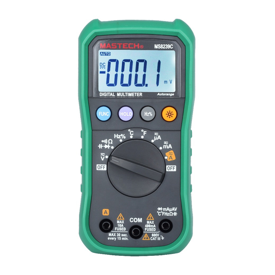
- Page 1 MS8239C Digital Multimeter User's Manual MS8239C AUTO MAX DIGITAL MULTIMETER Autorange FUNC HOLD mAµAV 600V CAT III °C°FHzΩ IEC61010-1 600V MAX 400mA FUSED FUSED...
-
Page 2: Table Of Contents
CONTENTS CONTENTS Overview..........1 Frequency/Duty Ratio Measurement......13 Safety Instructions......1 Temperature Measurement....14 Safe Working Habits......2 General Specifications......14 Electric Symbols.......4 Accuracy Indicators......15 Meter Instructions......5 Meter Appearance......5 DC Voltage...........15 AC Voltage...........16 Display..........6 Resistance...........16 Keys Operation.........7 Capacitance.........17 Automatic Power-Off Function...7 Diode/Continuity Measurement.....17 Measuring Operation......8 DC Current...........18 DC/AC Voltage Measurement.....8 AC Current...........18 DC/AC Current Measurement... -
Page 3: Overview
“safety information” and “warning and procedures methods: related notes” carefully before using the meter. The MS8239C is a small hand-held, safe and reliable • Check the case before using the meter. Don't use the 3.5” digital auto measuring range multi-meter with meter with damaged case. -
Page 4: Electric Symbols
• When connecting circuits, connect the common test Electric Symbols line first, then connect the charged test line. When Important safety information disconnecting circuits, disconnect the charged test line first, then disconnect the common test line. AC (Alternating Current) • Before measuring resistance, continuity, and diodes, first turn off power and discharge all high voltage DC (Direct Current) capacitors. -
Page 5: Meter Instructions
(8) All common input jacks for measuring (connected Meter Appearance with the black test probe). (9) Positive input jack of voltage, resistance, capacitance, temperature, frequency, mA current, diode and continuity (connected with the MS8239C AUTO MAX red test probe) Display DIGITAL MULTIMETER Autorange... -
Page 6: Keys Operation
Keys Operation Measuring Operation AC/DC Voltage Measurement: “FUNC” key: Function selection key, switch measurement function Rotate function selection switch to voltage by pressing “FUNC” key, combined with switch measurement position. “HOLD” key: Press “FUNC” key to select AC or DC voltage Data hold key, press “HOLD”... -
Page 7: Resistance Measurement
Turn off the circuit to be tested. The black test Connect black and red test probe to COM input probe is connected to one end of disconnected jack and VΩmA input jack, respectively. circuit (low voltage relatively), and the red test Measure the resistance of circuit to be tested with probe is connected to the other end of disconnected other ends of test probes. -
Page 8: Capacitance Measurement
Capacitance Measurement: Continuity Measurement: Rotate function selection switch to capacitance Rotate function selection switch to continuity measurement position, and turn off the power to measurement position, and turn off the power to the circuit to be tested the circuit to be tested If needed, press “FUNC”... -
Page 9: Frequency/Duty Ratio Measurement
Temperature Measurement The meter will display the diode's forward bias voltage value. If the test probe polarity is reversed, Rotate function selection switch to temperature the meter will display “OL”, which distinguishes (select Celsius degree or Fahrenheit degree as the diode's cathode and anode. required) measurement position. -
Page 10: Accuracy Indicators
• Fuse protection: grade mA: fuse F400mA/500V AC Voltage grade 10A: fuse F10A/500V Measuring range Accuracy Resolution • Sampling rate: about 3 times/s. 0.001V • Display: 3 3/4 bits of digit LCD display. 0.01V • Over-range indication: LCD will show “OL”. ±(1.2% of reading +5 digits) •... -
Page 11: Capacitance
Capacitance DC Current Measuring range Accuracy Measuring range Accuracy Resolution Resolution 400µA 0.1µA 0.001nF 4000µA 1µA 50nF 0.01nF ±(1.0% of reading +5 digits) 0.01µA 500nF 0.1nF 40mA ±(3.0% of reading +5 digits) 5µF 0.001µA 0.1µA 400mA 50µF 0.01µA 0.01A ±(2.0% of reading +10digits) 100µF 0.1µA Overload protection: grade mA: Fuse (F400mA/600V) -
Page 12: Maintenance
Maximum input current: grade mA: 200mA DC or AC To clean input socket: RMS; grade 10A: 10A DC or AC RMS Turn off the meter and pull out all the test probes When measured current is greater than 2A, the from the input jack. -
Page 13: Replace Fuse
Replace Fuse Warning To avoid electric shock or personal injury, before opening back cover to replace fuse, turn off the meter and disconnect the test probe from the measurement circuit. To replace fuse: Turn off the power to the meter. Remove all test probes from the input jacks. - Page 14 HYS007240...
Need help?
Do you have a question about the MS8239C and is the answer not in the manual?
Questions and answers