Table of Contents
Advertisement
Advertisement
Table of Contents
Troubleshooting

Subscribe to Our Youtube Channel
Related Manuals for HP t630 Thin Client


Summary of Contents for HP t630 Thin Client
-
Page 1: Troubleshooting Guide
Troubleshooting Guide HP t630 Thin Client... - Page 2 HP End User License Agreement (EULA). If Not all features are available in all editions of you do not accept these license terms, your sole The information contained herein is subject to Windows.
-
Page 3: About This Book
About this book WARNING! Text set off in this manner indicates that failure to follow directions could result in bodily harm or loss of life. CAUTION: Text set off in this manner indicates that failure to follow directions could result in damage to equipment or loss of information. - Page 4 About this book...
-
Page 5: Table Of Contents
Computer Setup (F10) Utilities ............................21 Using Computer Setup (F10) Utilities ......................21 Computer Setup—File ............................23 Computer Setup—Storage ..........................24 Computer Setup—Security ..........................25 Computer Setup—Power ..........................26 Computer Setup—Advanced ........................... 27 Changing BIOS Settings from the HP BIOS Configure Utility (HPBCU) ................28... - Page 6 Updating or restoring a BIOS ..............................42 Appendix F Using HP PC Hardware Diagnostics (UEFI) ........................44 Downloading HP PC Hardware Diagnostics (UEFI) to a USB device ................44 Appendix G Power cord set requirements ............................. 46 General requirements ................................46 Japanese power cord requirements ...........................
-
Page 7: Product Features
Various options are available for your thin client. For more information about some of the available options, go to the HP website at http://www.hp.com and search for your specific thin client. -
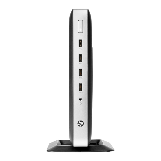
Page 8: Front Panel Components
Front panel components For more information, go to http://www.hp.com/go/quickspecs and search for your specific thin client to find the QuickSpecs. Item Component Item Component Headset jack Flash drive activity LED USB 3.0 ports (2) Power button USB 2.0 ports (2) -
Page 9: Rear Panel Components
Rear panel components For more information, go to http://www.hp.com/go/quickspecs/ and search for your specific thin client to find the QuickSpecs. Item Component Item Component RJ-45 (network) jack Audio-out (headphone)/Audio-in (microphone) combo jack PS/2 keyboard port Optional port. If used, may provide dual coaxial cable... -
Page 10: Serial Number Location
Serial number location Every thin client includes a unique serial number located as shown in the following illustration. Have this number available when contacting HP customer service for assistance. Chapter 1 Product features... -
Page 11: Setup
To reduce the risk of serious injury, read the Safety & Comfort Guide. It describes proper workstation setup, posture, and health and work habits for thin client users, and provides important electrical and mechanical safety information. The Safety & Comfort Guide is located on the HP website at http://www.hp.com/ergo. WARNING! Energized parts inside. -
Page 12: Attaching The Stand
Attaching the stand CAUTION: Unless the thin client is mounted with the HP Quick Release, it must be operated with the stand attached to ensure proper airflow around the thin client. Adjusting the stand The stand can be adjusted into two configurations: square for the horizontal position and rectangular for the vertical position. - Page 13 Position the stand over the bottom of the thin client and line up the captive screws in the stand with the screw holes in the thin client. Tighten the captive screws securely. ● Attach the stand to the right side of the thin client to use it in the horizontal orientation. Lay the thin client down with the right side up and locate the two screw holes in the grid on the right side of the thin client.
-
Page 14: Connecting The Ac Power Cord
NOTE: An optional Quick Release mounting bracket is available from HP for mounting the thin client to a wall, desk, or swing arm. When the mounting bracket is used, do not install the thin client with the I/O ports oriented towards the ground. -
Page 15: Securing The Thin Client
Securing the thin client These thin clients are designed to accept a security cable. The security cable prevents unauthorized removal of the thin client, as well as preventing access to the secure compartment. To order this option, go to the HP website at http://www.hp.com... -
Page 16: Hardware Changes
DO NOT use any access panel except the one that is provided by HP for use with this thin client. Before removing the access panel, be sure that the thin client is turned off and the AC power cord is disconnected from the AC outlet. - Page 17 CAUTION: Regardless of the power-on state, voltage is always present on the system board as long as the system is plugged into an active AC outlet. You must disconnect the AC power cord to avoid damage to the internal components of the thin client. Remove the stand from the thin client.
-
Page 18: Replacing The Access Panel
Replacing the access panel To replace the access panel: Position the access panel on the chassis, approximately 6 mm (.24 in) inside the edge of the chassis. Slide the panel toward the front of the chassis (1) until it locks into place. Move the access panel latch (2) to the left to secure the access panel. -
Page 19: Locating Internal Components
Locating internal components Item Component Item Component Battery USB 3.0 port System memory DIMM1 M.2 socket for a 42 mm, 60 mm, or 80 mm M.2 primary storage module System memory DIMM2 M.2 socket for a 42 mm M.2 secondary storage module CMOS button Locating internal components... -
Page 20: Replacing An M.2 Storage Module
Replacing an M.2 storage module Two M.2 storage module sockets can be installed in the thin client: ● A 42 mm, 60 mm, or 80 mm M.2 primary storage module may be installed in one socket. ● A 42 mm M.2 secondary storage module may be installed in the other socket. To remove an M.2 flash storage module: Remove/disengage any security devices that prohibit opening the thin client. - Page 21 Pull the screw kit off of the storage module and attach it to the replacement storage module. Slide the new storage module into the M.2 socket on the system board and press the module connectors firmly into the socket. NOTE: A storage module can be installed in only one way.
-
Page 22: Removing And Replacing The Battery
Press the storage module down and use a screwdriver to tighten the screw and secure the module to the system board. Replace and latch the access panel, and then reinstall the rear I/O panel. See Removing and replacing the access panel on page Replace the thin client stand. - Page 23 Reconnect the AC power cord and turn on the thin client. Lock any security devices that were disengaged when the thin client access panel was removed. HP encourages customers to recycle used electronic hardware, HP original print cartridges, and rechargeable batteries. For more information about recycling programs, go to http://www.hp.com...
-
Page 24: Installing An Internal Usb Flash Drive
Installing an internal USB flash drive There is one USB 3.0 flash drive port on the system board. To install a USB flash drive: Remove/disengage any security devices that prohibit opening the thin client. Remove all removable media, such as USB flash drives, from the thin client. Turn off the thin client properly through the operating system, and then turn off any external devices. -
Page 25: Upgrading System Memory
Upgrading system memory The memory socket on the system board is populated with one memory module. To achieve the maximum memory support, you can populate each memory socket with up to 16 GB of memory each (32 GB total). For proper system operation, the memory module must adhere to the following specifications: ●... - Page 26 Remove the thin client access panel. See Removing and replacing the access panel on page WARNING! To reduce risk of personal injury from hot surfaces, allow the internal system components to cool before you touch them. Locate the memory module on the system board. See Locating internal components on page To remove a memory module , press outward on the two latches on each side of the memory module (1), rotate the memory module up, and then pull the memory module out of the socket (2).
-
Page 27: Appendix A Computer Setup (F10) Utility, Bios Settings
Computer Setup (F10) Utility, BIOS Settings Computer Setup (F10) Utilities Use Computer Setup (F10) Utility to do the following: ● Change factory default settings. Set the system date and time. ● ● Set, view, change, or verify the system configuration, including settings for processor, graphics, memory, audio, storage, communications, and input devices. - Page 28 Use the arrow (left and right) keys to select the appropriate heading. Use the arrow (up and down) keys to select the option you want, then press enter. To return to the Computer Setup Utilities menu, press esc. To apply and save changes, select File > Save Changes and Exit. ●...
-
Page 29: Computer Setup-File
Computer Setup—File NOTE: Support for specific Computer Setup options may vary depending on the hardware configuration. Option Description System Information Lists: ● Product name SKU number ● ● System Board CT Number ● Processor type ● Processor speed ● Processor stepping ●... -
Page 30: Computer Setup-Storage
Computer Setup—Storage Option Description Device Configuration Lists all installed BIOS-controlled storage devices. When a device is selected, detailed information and options are displayed. The following options may be presented: Hard Disk: Size, model, firmware version, serial number. Storage Options SATA Emulation CAUTION: SATA emulation changes may prevent access to existing drive data and degrade or corrupt established volumes. -
Page 31: Computer Setup-Security
Computer Setup—Security NOTE: Support for specific Computer Setup options may vary depending on the hardware configuration. Table A-1 Computer Setup—Security Option Description Setup Password Allows you to set and enable a setup (administrator) password. NOTE: If the setup password is set, it is required to change Computer Setup options, flash the ROM, and make changes to certain plug and play settings under Windows. -
Page 32: Computer Setup-Power
Clear Secure Boot Keys (Clear/Don’t Clear). Lets you clear the Secure Boot Key. ● Key ownership (HP keys/Customer keys). Lets you change the keys of different owners. Fast Boot (Enable/Disable) – Enable Fast Boot cause system boot by initializing a minimal set of devices which is required to launch active boot option. -
Page 33: Computer Setup-Advanced
Computer Setup—Advanced NOTE: Support for specific Computer Setup options may vary depending on the hardware configuration. Table A-3 Computer Setup—Advanced (for advanced users) Option Heading Power-On Options Allows you to set: ● POST messages (enable/disable) – Default is disabled. ● Press the ESC key for Startup Menu (Displayed/Hidden). -
Page 34: Changing Bios Settings From The Hp Bios Configure Utility (Hpbcu)
Changing BIOS Settings from the HP BIOS Configure Utility (HPBCU) Some BIOS settings may be changed locally within the operating system without having to go through the F10 utility. This table identifies the items that can be controlled with this method. - Page 35 Disable Enable Integrated Graphics Auto Disable, Force UMA Frame Buffer Size 512M 256M, 1G Num Lock State at Power- On Internal Speaker Enable Disable Onboard NIC Option ROM Disable Download Changing BIOS Settings from the HP BIOS Configure Utility (HPBCU)
-
Page 36: Appendix B Diagnostics And Troubleshooting
Diagnostics and troubleshooting LEDs Table B-1 Power and IDE Flash Activity LEDs Status Power LED Off When the unit is plugged into the wall socket and the Power LED is off, the unit is powered off. However, the network can trigger a Wake On LAN event in order to perform management functions. Power LED On Displays during boot sequence and while the unit is on. -
Page 37: Wake-On Lan
Wake-on LAN Wake-on LAN (WOL) allows a computer to be turned on or resumed from sleep or hibernation state by a network message. You can enable or disable WOL in Computer Setup using the S5 Maximum Power Savings setting. To enable or disable WOL: Turn on or restart the computer. -
Page 38: Resetting The Setup And Power-On Passwords
Resetting the Setup and Power-on passwords You can reset the Setup and Power-on passwords as follows: Turn off the computer and disconnect the power cord from the power outlet. Remove the side access panel and the metal side cover. Remove the password jumper from the system board header labeled PSWD/E49. Replace the metal side cover and the side access panel. -
Page 39: Interpreting Post Diagnostic Front Panel Leds And Audible Codes
LEDs remove a memory module. continue until problem is solved. Reseat memory modules. Replace memory modules one at a time to isolate the faulty module. Replace third-party memory with HP memory. Interpreting POST diagnostic front panel LEDs and audible codes... - Page 40 Table B-3 Diagnostic front panel LEDs and audible codes (continued) Activity Beeps Possible Cause Recommended Action Replace the system board. Red Power LED flashes six times, Pre-video graphics error. For systems with a graphics card: once every second, followed by a Reseat the graphics card.
-
Page 41: Post Numeric Codes And Text Messages
POST numeric codes and text messages This section covers those POST errors that have numeric codes associated with them. The section also includes some text messages that may be encountered during POST. NOTE: The computer will beep once after a POST text message is displayed on the screen. Table B-4 Numeric Codes and Text Messages Control panel message... - Page 42 System test using F2 Diagnostics. Apply hard drive firmware patch if applicable. (Available at http://www.hp.com/support.) Back up contents and replace hard drive. Invalid Electronic Serial Number Electronic serial number is missing. Enter the correct serial number in Computer Setup.
-
Page 43: Troubleshooting
Troubleshooting Basic troubleshooting If the thin client is experiencing operating problems or will not power on, review the following items. Table B-5 Power-on troubleshooting Issue Procedures The thin client unit is experiencing operating Ensure that the following connectors are securely plugged into the thin client unit: problems. -
Page 44: Diskless (No-Flash) Unit Troubleshooting
Diskless (No-Flash) unit troubleshooting This section is only for those units that do not have ATA Flash capability. Because there is no ATA Flash in this model the boot priority sequence is: USB device ● ● When the unit boots, the monitor should display the following information: Table B-6 Diskless unit troubleshooting Item... -
Page 45: Configuring A Pxe Server
NOTE: All PXE software is supported by authorized service providers on a warranty or service contract basis. Customers who call the HP Customer Service Center with PXE issues and questions should be referred to their PXE provider for assistance. Additionally, refer to the following: –... -
Page 46: Appendix C Using Hp Thinupdate To Restore The Image
● The Image Capture feature lets you capture an image from an HP thin client and save it to a USB flash drive, which can be used to deploy the image to other thin clients. ●... -
Page 47: Appendix D Device Management
The t630 includes a license for HP Device Manager and has a Device Manager agent pre-installed. HP Device Manager is a thin client optimized management tool used to manage the full life cycle of HP thin clients to include Discover, Asset Management, Deployment and Configuration. For more information on HP Device Manager, please visit www.hp.com/go/hpdm. -
Page 48: Appendix E System Bios
HP Device Manager HP Device Manager can be used to update the BIOS of a thin client. Customers can use a pre-built BIOS add-on or can use the standard BIOS upgrade package along with an HP Device Manager File and Registry template. For more information on HP Device Manager File and Registry templates, review the HP Device Manager User Guide found at www.hp.com/go/hpdm. - Page 49 process locates the binary image, it attempts the recovery process. The automatic recovery continues until it successfully restores or updates the BIOS. If the system has a BIOS Setup password, you may need to use the Startup Menu / Utilities submenu to flash the BIOS manually after providing the password. Sometimes there are restrictions on which BIOS versions are allowed to be installed on a platform.
-
Page 50: Appendix F Using Hp Pc Hardware Diagnostics (Uefi)
NOTE: The HP PC Hardware Diagnostics (UEFI) download instructions are provided in English only, and you must use a Windows computer to download and create the HP UEFI support environment because only .exe files are offered. There are two options to download HP PC Hardware Diagnostics to a USB device. - Page 51 Enter the product name or number. – or – Select Identify now to let HP automatically detect your product. Select your computer, and then select your operating system. In the Diagnostic section, follow the on-screen instructions to select and download the UEFI version you want.
-
Page 52: Appendix G Power Cord Set Requirements
Power cord set requirements The power supplies on some computers have external power switches. The voltage select switch feature on the computer permits it to operate from any line voltage between 100-120 or 220-240 volts AC. Power supplies on those computers that do not have external power switches are equipped with internal switches that sense the incoming voltage and automatically switch to the proper voltage. -
Page 53: Country-Specific Requirements
Country-specific requirements Additional requirements specific to a country are shown in parentheses and explained below. Country Accrediting Agency Country Accrediting Agency Australia (1) EANSW Italy (1) Austria (1) Japan (3) METI Belgium (1) CEBC Norway (1) NEMKO Canada (2) Sweden (1) SEMKO Denmark (1) DEMKO... -
Page 54: Appendix H Statement Of Volatility
Download the latest BIOS for your model off of the HP website. Follow the instructions to flash the BIOS that are found on the website. Restart the system, and while system is powering on (after the HP splash screen, if displayed) press the key to enter the BIOS setup screen. - Page 55 The information contained herein is subject to change without notice. The only warranties for HP products and services are set forth in the express warranty statements accompanying such products and services. Nothing herein should be construed as constituting an additional warranty.
-
Page 56: Appendix I Specifications
Specifications For the latest specifications or additional specifications on the thin client, go to http://www.hp.com/go/ quickspecs/ and search for your specific thin client to find the QuickSpecs. Item Value Value Dimensions (without stand) 42 mm 1.65 in. Width 220 mm 8.66 in... -
Page 57: Index
AC power cord connection 8 access panel 10 access panel battery 16 hardware specifications 50 removing 10 replacing HP PC Hardware Diagnostics (UEFI) replacing 12 access panel 12 using 44 audible codes 33 battery 16 humidity specifications 50 M.2 storage module 14... - Page 58 5, 10, 18, 20 electric shock 5, 10, 16 grounding plug 5, 10 NIC receptacles 5, 10 websites HP 1 Index...
Need help?
Do you have a question about the t630 Thin Client and is the answer not in the manual?
Questions and answers